Advances in high-capacity Li2MSiO4 (M = Mn, Fe, Co, Ni, …) cathode materials for lithium-ion batteries

H.-N. Girish and G.-Q. Shao *
State Key Laboratory of Advanced Technology for Materials Synthesis and Processing, Wuhan University of Technology, Wuhan 430070, China. E-mail: gqshao@whut.edu.cn; Fax: +86 27 87210216; Tel: +86 27 87210216

Received 11th September 2015 , Accepted 30th October 2015

First published on 30th October 2015


Abstract

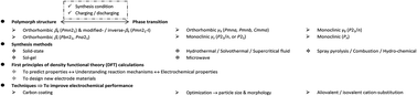
The orthosilicate, Li2MSiO4 (M = Mn, Fe, Co, Ni, …), is a competitive cathode material for next generation high-capacity (∼330 mA h g−1 with a possible 2 Li+ extraction per formula unit) rechargeable lithium-ion batteries. It is an alternative to other polyanionic compounds because the raw materials of Fe/Mn-containing oxidates and silica are abundant, cost effective, very safe, environmentally friendly, and its Si–O bond is at least as stable as other polyoxyanion groups with an excellent cycling performance. This review highlights the research progress related to the Li2MSiO4 cathode materials in terms of the phase transition of the structure, synthetic methods and techniques for improving the electrochemical performance.


image file: c5ra18594g-p1.tif

H.-N. Girish

Dr H.-N. Girish received his Bachelor, Master and PhD degree at Uni. of Mysore, Karnataka, India under the supervision of Prof. B. Basavalingu. He is currently working as a postdoctoral researcher in Prof. G.-Q. Shao’s group in the State Key Lab of Adv. Technol. for Mater. Syn. Proc., Wuhan Uni. of Technol., Wuhan, Hubei, China. Present research involves the synthesis, phase transition and electrochemical properties of orthosilicate Li2MSiO4 (M = Mn, Fe, Co, Ni, etc.) cathode materials for rechargeable Li-ion batteries.

image file: c5ra18594g-p2.tif

G.-Q. Shao

Dr Gang-Qin Shao (G.-Q. Shao), has been a professor at the State Key Lab of Adv. Technol. for Mater. Syn. Proc., Wuhan Uni. of Technol. (WUT), a postdoctoral fellow at Shanghai Inst. Ceram., a PhD and M.Eng. student at WUT, and a B.Eng. student at South China Uni. of Technol., and has been working as a visiting scholar in DMSE, Massachusetts Institute of Technology and in Geballe Lab for Adv. Mater., Stanford Uni., USA, and worked in Yangtze River Sci. Res. Inst., China. Current research interests include: (1) advanced inorganic materials – structure constitution, resolution and refinement; (2) novel functional materials such as rechargeable Li-ion batteries & ferroelectric/magnetoelectric materials.


A. Introduction

Lithium-ion batteries (LIBs) can effectively store energy in the form of chemicals. Cathode materials have become a hot topic for LIBs. Early cathode materials such as LiCoO2, LiNiO2, LiMn2O4, LiMnO2, etc. have limitations related to cost, toxicity to the environment, and inherent chemical and thermal stability in their applications. Extensive research can be found, which has focused on developing suitable promising cathodes1–6 in the field of polyanionic materials such as phosphates (LiMPO4, Li3M2(PO4)3, LiMP2O7, M = Mn, Fe, Co, Ni, …, the same below),7–17 silicates (Li2MSiO4, Li2VOSiO4),18–24 fluorophosphates (Li2MPO4F, Li2VPO4F),25 fluorosilicates (R2SiF6, R = K, Na, NH4+, …), sulfates (LiCoOSO4, LiNiOSO4, Li2NiSO4),26,27 tavorite fluorosulphates (LiMSO4F)28 and borates (LiMBO3).29–33 Recently the lithium transition-metal (TM) orthosilicate, Li2MSiO4 (M = Mn, Fe, Co, Ni, …), has been attracting considerable attention for use as a new generation cathode. It is an alternative to phosphates, or possibly a better option because of its strong Si–O covalent bond (at least as stable as other polyoxyanion groups) resulting in high chemical stability towards electrolytes. It has a high theoretical capacity (∼330 mA h g−1) which can potentially extract more than one lithium ion per formula unit (i.e. 1 Li+/f.u.).18,23,34–39

Calculations of the electrochemical potential of lithium insertion or extraction show two processes:

 
Li2M2+SiO4 → LiM3+SiO4 + Li+ (1)
 
LiM3+SiO4 → M4+SiO4 + Li+ (2)

Depending on the TM type, as shown in Fig. 1, the potential in reaction (1) (green square) varies from 3.1 V (for Fe) to 4.1–4.6 V (for Mn, Co and Ni), while that in reaction (2) (red circle) is in the range 4.5–5.1 V. The extraction of the 2nd Li+ requires the application of a high potential above 4.5 V which is a challenge for electrolytes.


image file: c5ra18594g-f1.tif
Fig. 1 Variation of Li insertion voltage by M2+/M3+ and M3+/M4+ in Li2MSiO4.18

Li2MnSiO4 has more advantages than Li2FeSiO4 with regards to cell safety, ease of preparation and cost effectiveness. The Mn3+ ↔ Mn4+ conversion provides a higher potential than Mn2+/Mn3+ and Fe2+/Fe3+ (it is yet to be clarified whether this involved an Fe3+/Fe4+ redox couple which might just be an electrolyte degradation18,38,40,41). During oxidation, the short Mn–O bonds in the MnO4 tetrahedron decrease in correlation with the increase in the Mn valance state, while the long Mn–O bonds remain unchanged.42 In practical applications, Li2MnSiO4 is limited as a cathode by its low electronic conductivity of ∼5 × 10⁻¹⁶ S cm−1 at room temperature (RT) (and ∼3 × 10⁻¹⁴ S cm−1 at 60 °C), which is 5–6 orders of magnitude smaller than that of LiFePO4 at RT. The preparation of pure Li2MnSiO4 even at temperatures up to 800 °C is not trivial due to the possible presence of mixed phases and impurities such as MnO, MnSiO3, Li2SiO3, etc.43–46

Co- or Ni-containing salts for preparing Li2CoSiO4 and Li2NiSiO4 are commercially expensive and environmentally toxic. Li2NiSiO4, with the lowest band-gap, does not have the shortcomings of Mn derivatives18 but the delithiation potentials (>4.6 V) of Li2CoSiO4 and Li2NiSiO4 are too high to make the present electrolytes suitable Li+ diffusion media. In the same way, their kinetic properties make preparation difficult and cause poor delithiation–lithiation during the charge–discharge process.18,36,47–49

Otherwise, defects such as poor reversibility that are associated with Li2MSiO4 have become a huge obstacle to their extensive application in electric vehicles (EV) and plug-in hybrid electric vehicles (PHEV).50–53 Various methods have been developed to improve their electrochemical properties, such as controlling the particle size and morphology (e.g., nanosheet/rod-like particles),45,54–57 cation substitution (Mg2+, Al3+, Cr2+, etc.)56,58–65 and surface-coating with conductive materials.66–80 For surface-coating methods, an appropriate carbon coating has been widely used,81–84 because it not only improves the electronic conductivity but also reduces the particle size, which are favourable for enhancing the electrochemical properties.

This review will explain the polymorphic structure of Li2MSiO4 and its phase transitions and summarize progress in its research, methods for its synthesis and techniques for improving its electrochemical performance.

B. Polymorphic structure of Li2MSiO4 and its phase transitions

The orthosilicate (Li2MSiO4) represents a family having an iso-structure of tetrahedral lithiophosphate (Li3PO4). The crystal structure of Li2MSiO4 consists of distorted hexagonal close-packing of oxygen ions with half tetrahedral sites occupied by Li, M (M = Mn, Fe, Co, Ni, …) and Si cations, so that face sharing between pairs of tetrahedral sites is avoided. These tetrahedral structures exhibit a rich polymorphism.

Li3PO4 crystallizes in the “α-phase formed in low temperature”, “β-phase in high temperature” and “γ-phase above 1170 °C”.45,85 Several temperature/pressure-dependent polymorphs of Li2MSiO4, namely high temperature monoclinic γos (P21/n) and orthorhombic γII (Pmna, Pmnb, Cmma, γ-Li3PO4), and low temperature orthorhombic βI (Pbn21, Pna21, β-Li3PO4)/βII (Pmn21, β-Li3PO4), can be stabilised/influenced significantly by the synthetic conditions and also the electrochemical cyclic behavior.86 These phases may be quenched to RT and exhibit long-term stability. Metastable monoclinic (Pn) Li2MnSiO4 prepared by ion-exchange from Na2MnSiO4 was also reported.83 Different phase structures of Li2MSiO4 polymorphs are shown in Fig. 2 and discussed below.38,45,83,86–92


image file: c5ra18594g-f2.tif
Fig. 2 Structures of Li2MSiO4: (a) orthorhombic βII (Pmn21); (b) orthorhombic β1 (Pbn21, Pna21); (c) orthorhombic γII (Pmna, Pmnb, Cmma); (d) monoclinic γs (P21/n, P21); (e) monoclinic γ0 (P21/n); (f) monoclinic Pn.38,45,83,86–92 SiO4 (yellow); MO4 (brown/green); LiO4 (blue/orange); light and dark blue tetrahedra represent crystallographically distinct Li sites.

(a) Orthorhombic βII structure (Pmn21) and modified-/inverse-βII structure (Pmn21-I): all the tetrahedra point in the same direction, perpendicular to the close-packed planes, and share only corners with each other. Chains of LiO4 are along the a-axis and parallel to chains of alternating MO4 and SiO4 (Fig. 2a).45

In the modified-/inverse-βII structure (e.g. the cycled polymorph of Li2FeSiO4), all tetrahedra point in the same direction along the c-axis/b-axis and are linked only by corner-sharing. The SiO4 tetrahedra are isolated from each other, sharing corners with LiO4 and (Li/Fe)O4 tetrahedra.86,90,91 This the more stable configuration at low temperature.

(b) Orthorhombic βI structure (Pbn21, Pna21): all tetrahedra point in same direction with chains of alternating LiO4 and MO4 tetrahedra along the a-axis, parallel to chains of alternating LiO4 and SiO4 tetrahedra (Fig. 2b).38,87–90,92

Quoirin et al. prepared an orthorhombic Li2FeSiO4 (Pna21, βI) by precipitation at 100 °C in air which was optionally in the space group of Pccn. It might be an intermediate between the orthorhombic Pmn21II) and monoclinic P21/ns) phases.87–89

(c) Orthorhombic γII structure (Pmna, Pmnb, Cmma): the tetrahedra are arranged in groups of three with the central tetrahedron pointing in the opposite direction to the outer two, with which it shares edges; the group of 3 edge-sharing tetrahedra consist of the sequence Li–M–Li (Fig. 2c and the inset).45

(d) Monoclinic γs structure (P21/n, previously designated P21 (ref. 93–95)): half of the tetrahedra point in reverse directions, containing pairs of LiO4/MO4 and LiO4/LiO4 edge-sharing tetrahedra (Fig. 2d and the inset).45

(e) Monoclinic γ0 structure (P21/n): similar to the γII structure, the group of 3 edge-sharing tetrahedra consist of the sequence Li–Li–M (Fig. 2e).45

(f) Monoclinic structure (Pn): similar to the orthorhombic βII structure (Pmn21), it is a metastable form of Li2MnSiO4 and can convert to βII above 370 °C. Here the MnO4 and SiO4 tetrahedra point in the same direction parallel to the c-axis (Fig. 2f).83

Fig. 3 shows a schematic diagram of the temperature/pressure-dependent polymorphs of Li2MSiO4 with phase transitions. Table 1 shows the reported lattice parameters of Li2MSiO4 polymorphs (M = Fe, Mn, Co, Ni).


image file: c5ra18594g-f3.tif
Fig. 3 Schematic diagram of temperature/pressure-dependent polymorphs of Li2MSiO4 with phase transitions.
Table 1 The reported lattice parameters of Li2MSiO4 polymorphs (M = Fe, Mn, Co, Ni)
Li2MSiO4 x Space group Crystal system a b c α β γ/° Refs.
Li2FeSiO4 Pbn21I) Orthorhombic 6.2652(1) 10.8121(1) 4.9504(1) 90 90 90 88 and 89
Pna21I) Orthorhombic 10.724(5) 6.260(7) 4.958(6) 90 90 90 87–89
Pmn21II) Orthorhombic 6.2709(8) 5.3382(7) 4.9651(7) 90 90 90 88 and 89
Pmn21II) Orthorhombic 6.2661 5.3295 5.0148 90 90 90 23
Pmn21II) Orthorhombic 6.271(1) 5.336(1) 4.9607(9) 90 90 90 37
Pmn21II) Orthorhombic 6.3246 5.3817 4.9967 90 90 90 18
Pmn21II) Orthorhombic 6.313 5.393 4.979 90 90 90 39
PmnbII) Orthorhombic 6.2853(5) 10.6592(8) 5.0367(4) 90 90 90 103
PnmaII) Orthorhombic 10.656 6.285 5.038 90 90 90 88
CmmaII) Orthorhombic 10.664 12.540 5.022 90 90 90 88
P21/ns) Monoclinic 8.2253(5) 5.0220(1) 8.2381(4) 90 99.230 90 93
P21/ns) Monoclinic 6.2835(7) 10.6572(1) 5.0386(5) 90 89.941 90 103
P21s) Monoclinic 8.2278(1) 5.0204(6) 8.2295(1) 90 99.231 90 95
Li2MnSiO4 Pmn21II) Orthorhombic 6.3109(9) 5.3800(9) 4.9662(8) 90 90 90 37
Pmn21II) Orthorhombic 6.308(3) 5.377(3) 4.988(9) 90 90 90 107
Pmn21II) Orthorhombic 6.3666 5.4329 4.0368 90 90 90 18
Pmn21II) Orthorhombic 6.308(9) 5.385(9) 4.999(6) 90 90 90 108
Pmn21II) Orthorhombic 6.3064 5.3893 4.9715 90 90 90 109
Pmn21II) Orthorhombic 6.3141 5.3702 4.9650 90 90 90 44
PmnbII) Orthorhombic 6.3126 10.7657 5.0118 90 90 90 44
P21/ns) Monoclinic 6.3368(1) 10.9146(2) 5.0730(1) 90 90.98 90 106
P21/ns) Monoclinic 6.3363(5) 10.8950(7) 5.07506(3) 90 90.99 90 44
Pn (metastable) Monoclinic 6.593(5) 5.402(1) 5.090(2) 90 89.7(3) 90 83
Li2CoSiO4 Pbn21I) Orthorhombic 6.253 10.685 4.929 90 90 90 92
Pmn21II) Orthorhombic 6.2599 10.6892 4.9287 90 90 90 85
Pmn21II) Orthorhombic 6.159 5.440 4.988 90 90 90 110
Pmn21II) Orthorhombic 6.287(6) 5.353(1) 4.937(1) 90 90 90 47
Pmn21II) Orthorhombic 6.267(9) 5.370(8) 4.939(4) 90 90 90 47
Pmn21II) Orthorhombic 6.2015 5.4378 4.9909 90 90 90 18
PmnbII) Orthorhombic 6.20 10.72 5.03 90 90 90 85
P21/no) Monoclinic 6.284 10.686 5.018 90 90.60 90 43
Li2NiSiO4 Pmn21II) Orthorhombic 6.2938 5.3702 4.9137 90 90 90 18
Pmn21II) Orthorhombic 6.274 5.365 4.921 90 90 90 111
Pmn21II) Orthorhombic 6.290 5.299 4.856 90 90 90 112
Li2(Fe1−xMnx)SiO4 (x = 0, 0.3, 0.5, 0.7, 1) x = 0 Pmn21II) Orthorhombic 6.2512 5.3425 5.0188 90 90 90 113
x = 0.3 6.2117 5.381 4.975      
x = 0.5 6.2581 5.3747 5.006      
x = 0.7 6.2851 5.381 5.0012      
x = 1 6.3099 5.394 5.0192      
Li2(Mn1−xFex)SiO4/C (x = 0, 0.2, 0.5, 0.8) x = 0 Pmn21II) Orthorhombic 90 90 90 109
x = 0.2      
x = 0.5      
x = 0.8      
Li2(Fe1−xMnx)SiO4 (x = 0, 0.2, 0.5, 1) x = 0 P21/ns) Monoclinic 8.244(8) 5.004(4) 8.244(8) 90 99.25 90 102
x = 0.2 P21/ns) Monoclinic 8.264(7) 5.020(7) 8.264(4) 90 99.00 90
  PmnbII) Orthorhombic 6.591(6) 9.462(7) 4.988(1) 90 90 90
x = 0.5 Pmn21II) Orthorhombic 6.284(0) 5.391(9) 5.015(1) 90 90 90
  P21/ns) Monoclinic 6.986(8) 8.030(9) 5.990(4) 90 95.19 90
x = 1 Pmn21II) Orthorhombic 6.299(9) 5.381(5) 4.974(2) 90 90 90
  PmnbII) Orthorhombic 5.929(5) 10.622(0) 4.961(1) 90 90 90
  P21/ns) Monoclinic 6.305(7) 11.098(7) 5.114(9) 90 92.44 90
Li2(Fe1−xMnx)SiO4/C (x = 0, 0.05, 0.1, 0.2, 0.3) Pmn21II) Orthorhombic 90 90 90 114
Li2(Fe0.5Mn0.5)SiO4 PmnbII) Orthorhombic 90 90 90 115
Li2(Fe0.5Mn0.5)SiO4/C Pmn21II) Orthorhombic 90 90 90 106


The differences among these polymorph structures mainly depend on the different arrangements of the cationic tetrahedra and the local order (order probes such as solid-state Magic Angle Spinning Nuclear Magnetic Resonance (MAS NMR) are very useful for identifying the obtained polymorphs and also their mixtures).96,97

B.1. Synthetic conditions for phase formation and phase transition in Li2MSiO4

The structures of Li2MSiO4 materials obtained from different synthetic methods further affect the lithium intercalation behavior.116 Among the various polymorphs, Li2MSiO4 with P21 symmetry has higher electronic conductivity48 but both high/low temperature orthorhombic structures are more stable than the monoclinic ones.44

Orthorhombic βII-Li2MSiO4 (Pmn21) can be formed at low temperature (150–200 °C) via hydrothermal methods,100,117–120 and at 600–800 °C via solid-state,37,73,81,99,121–128 sol–gel,41,57,78,84,108,129–138 spray pyrolysis,139,140 microwave141 and combustion142 methods, etc. It is very stable and easy to synthesize via all these techniques. For example, βII-Li2CoSiO4 was obtained via a hydrothermal technique at 150 °C and treatment at 700 °C,143 via a combustion route at 950 °C (ref. 144) and via a supercritical technique at 350 °C/38 MPa.145

Orthorhombic βI-Li2MSiO4 (Pbn21, Yamaguchi et al. named it βIl-Pbn21 previously92) is formed at a higher temperature than βIl-Pmn21 and little data have been reported for this phase.143–145 To the best of our knowledge, this phase is not yet reported for Li2MnSiO4.

Monoclinic γs-Li2MSiO4 (P21/n) is formed at a higher temperature than the βI- and βIl-phases in the temperature range 650–900 °C via solid-state,43,65,79,82,105 sol–gel56,61,63,129,146 and combustion43,147,148 methods. When the temperature was further increased to 800–1000 °C, an orthorhombic γII-phase (Cmma,87,88 Pnma149 or Pmnb44,85,87,88,100,103,129,150) resulted.

The β-phase is more stable than the γ-phase because the latter has a larger volume and requires a higher temperature for preparation and quenching.44

Li2FeSiO4 (LFS). Li2FeSiO4 crystallises in the orthorhombic βII (Pmn21), orthorhombic γII (Pmnb) and monoclinic γs (P21/n) phases. The inverse-βII structure (Pmn21-I, βII) is commonly formed at low temperatures. The monoclinic and orthorhombic structures stabilized depending on the synthetic method, different temperatures and carbon-coating technique.42,151

Nyten et al. obtained pure orthorhombic βII-Li2FeSiO4 (Pmn21) via a solid-state method.23,99,152,153 Quoirin et al. synthesized orthorhombic βI-Li2FeSiO4 (Pna21) via a wet chemical method at 100 °C, and orthorhombic γII-Li2FeSiO4 at 800 °C (Cmma)/900 °C (Pnma) via a solid-state method.87–89 Nishimura et al. prepared monoclinic γs-Li2FeSiO4 at 800 °C (P21/n).93–95 Sirisopanaporn et al. obtained orthorhombic γII-Li2FeSiO4 (Pmnb) at 900 °C that differs from the monoclinic γs-phase obtained by quenching from 800 °C.93,103 Bini et al. synthesized pure monoclinic γs-Li2FeSiO4 (P21/n) at 650 °C and pure orthorhombic γII-Li2FeSiO4 (Pmnb) at 900 °C via a sol–gel method.129

At 580 °C, complete phase transformation (starting at 400 °C) from orthorhombic (Pmn21, βII) to monoclinic (P21/n, γs) was observed and it was maintained up to 820 °C. Above 900 °C, it phase transformed again into an orthorhombic phase (Pmna, γII). This involved a statistical distribution of Li and Fe over the three (2/3 Li and 1/3 Fe) cation sites. By quenching the orthorhombic phase (Pmna, γII) from 900 °C, the monoclinic phase (P21/n, γs) was fully regained at 600 °C and maintained down to RT.101 Nanorods of orthorhombic Li2FeSiO4 (Pmn21, βII) were prepared at 200 °C over 6 days and phase transformed to a monoclinic phase (P21/n, γs) by heating at 600 °C.57

Li2MnSiO4 (LMS). There are four polymorphs of Li2MnSiO4 that form at ambient pressure. Two of them are orthorhombic βII and γII (i.e., Pmn21 and Pmnb). Another two are monoclinic P21s) and Pn.

Politaev et al. synthesized monoclinic (P21/n) Li2MnSiO4 at 950–1050 °C via a solid-state method.106 As mentioned before, the monoclinic Pn phase would transform to a stable orthorhombic phase (Pmn21) above 370 °C.83 By rate-cooling, a reversible phase transition can be observed in Li2MnSiO4. The sample (Pmnb) prepared at 800 °C via a solid-state method transformed to a P21/n phase when it cooled to RT at 200 K min−1, but the sample prepared at 700 °C formed the Pmn21 phase. This strongly indicated that the Pmnb phase transformed to orthorhombic disordered wurtzite-type structures.61

Bini et al. synthesized pure orthorhombic βII-Li2MnSiO4 (Pmn21) at 650 °C and mixed phases of orthorhombic γII (Pmnb)/monoclinic γs (P21/n) at 900 °C via a sol–gel method.129

By a hydrothermal technique and heating at 700 °C, orthorhombic Li2MnSiO4 (Pmn21, βII) was synthesized. Above 750 °C, it changed into a monoclinic (P21/n, γs) phase due to discontinuity in the c lattice parameter.101 By high pressure and high temperature processes, phase transitions can be observed with minimal impurities. The mixed phase of Li2MnSiO4 polymorphs, i.e. Pmnb and P21/n (63[thin space (1/6-em)]:[thin space (1/6-em)]13 w/w) was prepared at 900 °C over 10 h by slowly heating (2 °C min−1) with small impurities of MnO and Li2SiO3. At 60 kbar and 600 °C, the mixed phase transformed to a Pmn21 phase, being stable at 80 kbar and 900 °C with a new impurity of Mn2SiO4.43

The low-temperature orthorhombic forms are more stable (due to their large volume) than the monoclinic form, which can only be prepared above 900 °C.44,97 By increasing the process pressure/temperature, polymorphic transformations (Pmn21PmnbP21/n) will take place.44,144

Li2CoSiO4 (LCS). By varying the cooling rate, different polymorphs can form in Li2CoSiO4. Rapid cooling (0.5 °C min−1) from above 1000 °C resulted in the formation of PmnbII), while slow cooling (0.1 °C min−1) caused the formation of P21/no). Pmn21II) was formed by static heating of any other phase at 640–800 °C followed by quenching, and Pbn21I) was formed by slow cooling of Pmn21II).85

Monoclinic Li2CoSiO4 (P21/n, γo) was prepared at 950 °C and could transform (at 900 °C) into orthorhombic Pmn21Il) and Pbn21I) phases under 40/60 kbar, respectively. Both cell volumes are smaller than the monoclinic one.43 Orthorhombic Li2CoSiO4 (Pmn21, βII) was synthesized hydrothermally (150 °C/72 h). It transformed to the orthorhombic (Pbn21, βI) phase when heated at 700 °C over 2 h and to a monoclinic (P21/n, γo) phase at 1100 °C over 2 h.36 Otherwise, a considerably slow phase transition from βII ↔ γII at 170 °C has been determined by DTA studies.85

Li2NiSiO4 (LNS). Similar to the others in the family of Li2MSiO4, Li2NiSiO4 was most frequently observed to be an orthorhombic structure (Pmn21, βII). DFT calculations predict that Li2NiSiO4 has very high deintercalation voltages (4.5 V for Ni2+/Ni3+ and 5.2 V for Ni3+/Ni4+). This causes great difficulty for delithiation–lithiation during the charge–discharge process, even though the Li2NiSiO4 powder had been successfully synthesized.18,111,112
Li2(Mn1−xFex)SiO4/Li2(Fe1−xMnx)SiO4. This polymorph reflects the behavior of the end-members. For Fe-rich compositions, there is a gradual transition from Fe-like behavior to Mn-like behavior with increasing Mn-content.98 For Mn-rich compositions, there is a gradual transition from Mn-like behavior to Fe-like behavior with increasing Fe-content.102,109,113

Li2(Fe1−xMnx)SiO4 (x = 0, 0.2, 0.5, 1) was prepared via a modified sol–gel route using polyvinylpyrrolidone (PVP) as the chelating agent and carbon source. A pure monoclinic phase (P21/n) was obtained when x = 0. Monoclinic (P21/n) and orthorhombic (Pmnb) mixed phases were obtained when x = 0.2. Major orthorhombic (Pmn21) and minor monoclinic (P21/n) mixed phases were obtained when x = 0.5. Major orthorhombic (Pmn21), minor orthorhombic (Pmnb) and minor monoclinic (P21/n) mixed phases were obtained when x = 1.102

However, Li2(Fe1−xMnx)SiO4 (x = 0, 0.3, 0.5, 0.7, 1) obtained via a citric acid assisted sol–gel technique could be indexed to the orthorhombic phase (Pmn21), and the lattice parameters were similar.113 All samples of Li2(Fe1−xMnx)SiO4/C (x = 0, 0.05, 0.1, 0.2, 0.3) obtained via a solution route exhibited an orthorhombic phase (Pmn21) with a small amount of impurities such as Fe3O4 and Li4SiO4.114

Li2(MnxFe1−x)SiO4 (x = 0, 0.2, 0.5, 0.8) was prepared via a combination of spray pyrolysis at 400 °C and wet ball milling followed by annealing at 600 °C in N2 for 4 h. They exhibited a major orthorhombic phase (Pmn21) and small amounts of impurities such as FeO and SiO2 were found in materials with high Fe contents of 0.5 and 0.8.109

The thermal behavior of Li2(Fe0.5Mn0.5)SiO4 obtained via a sol–gel route, from RT to 950 °C, exhibited a major Pmnb phase (determined by in situ XRD) over the explored temperature range. A pure and stable Pmnb phase was formed at 950 °C.115

Li2(Fe0.5Mn0.5)SiO4/C was prepared using the precursors of Li2FeSiO4 and Li2MnSiO4 via a sol–gel route followed by heating at 600 °C for 10 h. It exhibited an orthorhombic phase (Pmn21) but the atomic ratio was not maintained.106

B.2. Phase transition while charging/discharging in Li2MSiO4

The rich polymorphism in Li2MSiO2 with the associated small transition energies is the main factor of the long-term cyclability. The phase transformation has structural, cyclic rate, applied current density, temperature and pressure dependence.43,100 The extraction/insertion of the 1st lithium out/into the host structure corresponds to the reaction Li2M2+SiO4 → LiM3+SiO4 + Li+ + e and is accompanied by the gradual changes of the local environment of the Li nuclei from the initial Li+–O–M2+ to Li+–O–M3+ bonds upon battery discharging. During discharge, phase transitions can be observed with the decrease in the crystal size upon cycling. The residual M3+ could explain the differences in the observed NMR spectra between the fully discharged sate and the pristine state.102 The influence of variations in the arrangements of MO4, in terms of the orientation, size and distortion, on the equilibrium potential were measured during the first oxidation of M2+ into M3+ for all polymorphs. The stronger M–O bonds result in a higher splitting energy between the bonding and antibonding states, which reduces the M2+/M3+ redox potential vs. Li+/Li0.100,154 An irreversible phase transformation was observed during the first charge, which accompanied a characteristic potential drop.23,99,104 XRD studies and theoretical calculations also suggested structural rearrangements involving the interchange of some M and Li sites.99 The applied current density is important to the kinetic phase transformation in the galvanostatic measurement.39,100

When the lithium ions were fully extracted from LixMSiO4 (M = Mn, Fe, Co, Ni, …), a larger volume expansion was found in the Fe-/Co-/Ni-systems compared to the Mn-system.111

Based on the structural characterization of the Pmn21-delithiated materials, Thomas et al. suggested that the voltage shift was due to a structural transformation of the host compound. Armstrong et al. suggested a Li2FeSiO4 phase transition from the monoclinic (P21) polymorph to the orthorhombic (Pmn21-I, inverse-βII) phase at 50 °C and at C/16 (1C = 160 mA g−1).174 Chen et al. confirmed the same phase transition happened at RT and at C/20.102 But the monoclinic phase could be preserved even after cycling.155

Nanocrystalline Li2(Fe1−xMnx)SiO4/C (x = 0, 0.2, 0.5, 1) powders were tested electrochemically, and characterized using XRD, 7Li MAS NMR spectroscopy, 57Fe Mössbauer spectroscopy and in situ XAS to study the structural evolution. Results showed the materials exhibited partially reversible structural changes upon cycling. Amorphization and structural rearrangements from the initial P21/n polymorph to Pmn21 occurred during the 1st charge–discharge cycle. Pmn21-Li2FeSiO4 exhibited a stable cycling performance over the subsequent 100 cycles due to the Fe2+/Fe3+ process. A competitive redox reaction between the Mn and Fe species was deduced for Li2Fe0.8Mn0.2SiO4 and Li2Fe0.5Mn0.5SiO4. A high conversion rate existed in the 1st charge from Fe2+/Mn2+ to Fe3+/Mn3+, while the presence of a small fraction (<7.5 mol%) of cations with higher oxidation states (Fe4+/Mn4+) could not be excluded.102

C. Synthetic methods

Table 2 gives a summary of synthetic methods, particle size, morphology, experimental conditions and physicochemical/electrochemical properties for Li2MSiO4 (M = Fe, Mn, Co). A high performance is observed in Li2FeSiO4 but it is yet to be clarified whether an Fe3+/Fe4+ couple could work.18,38,40,41 Besides Li2FeSiO4, the highest initial discharge of 313 mA h g−1 (0.05 C, nearly 2 Li+ extracted, 76.7% @ 20 cycles) was attained using PEDOT-coated Li2MnSiO4 at 40 °C, which was prepared via a supercritical technique156 and the second highest initial discharge of 253.4 mA h g−1 (0.03 C) was attained using Li2MnSiO4/C which was synthesized via a sol–gel technique.133
Table 2 Synthetic methods, conditions and physicochemical/electrochemical properties of Li2MSiO4 (M = Fe, Mn, Co)
Methods Temp./time/pressure (°C/h/MPa) Morphology Size (nm) Specific capacity (mA h g−1)/current density Retention (%)/cycles Refs.
Solid-state 650/10/— Agglomerate (Li2FeSiO4/C) 144.8/0.1 94.27/13 188
800/12/— Agglomerate (Li2MnSiO4/C) 30–80 129/0.06 —/10 128
650/8/— Agglomerate (LiFe0.9Mn0.1SiO4/C) 158.1/0.03 94.3/30 114
900/6/— Agglomerate (Li2FeSiO4/C/rGO) 28.5 191.6/0.1 91.3/60 127
700/10/— Agglomerate (Li1.95FeSiO4/C/CNTs) 30–70 148/0.2 99.2/100 159
700/8/— Spherical (Li2MnSiO4/C/graphene) 50 215.3/0.05 81.3/40 125
650/10/— Agglomerate (LiFe0.97Co0.03SiO4/C) 100–500 199/3.0 71.6/100 65
700/15/— Rounded (Li2FeSiO4/C) 200 102/— 91.8/10 126
700/10/— Agglomerate (Li1.95FeSiO4/C) 100 142/1.0/100 95.1/100 122
650/10/— Agglomerate (LiFe0.95V0.05SiO4/C) 7–10 220.4/0.1 78.7/50 161
700/10/— Agglomerate (Li2MnSiO4/C) 13.4–23.3 201.8/— 73.5/15 163
Sol–gel 800/—/— Spherical (Li2CoSiO4) 460 32/0.02 —/2 164
700/5/— Spherical (Li2MnSiO4) 25–30 161/0.05 77.6/50 137
700/10/— Irregular (Li2MnSiO4/C) 20–30 240/0.02 45.4/30 130
700/—/— Spherical (Li2MnSiO4) 25–30 113/— —/15 138
650/10/— Mesopores (Li2FeSiO4/C) 20–30 163/0.06 96/200 166
680/10/— Mesopores (Li2MnSiO4/C) 10–20 164.2/0.06 80/60 136
650/10/— Agglomerate (Li1.9Na0.1MnSiO4/C) 30 175/0.01 45/40 167
650/10/— Agglomerate LiFeSi0.9V0.1O4/C) 100–200 159/0.06 90/30 63
700/12/— Agglomerate (LiFe0.97Mg0.03SiO4) 100 153.2/0.06 98.6/50 61
700/10/— Agglomerate (LiMn0.8Fe0.2SiO4/C) 15–30 224/0.05 63.8/50 189
700/10/— Honeycomb (Li1.8MnSiO4) 6–8 147.1/0.03 83.3/25 168
600/10/— Aggregated (Li2FeSiO4/C-NHT) 20–30 195.5/0.1 —/50 190
700/10/— Agglomerate (Li0.5Mn0.5SiO4/C) 220 230.1/0.1 70.4/20 191
700/12/— Core–shell (Li2.05Mn0.95P0.05Si0.95O4) 30–60 170/0.06 —/60 170
700/12/— Agglomerate (LiFe0.97Zn0.03SiO4) 100 128/0.1 97.5/55 169
650/10/— Mesopores (Li2FeSiO4@CMK-3) 50 160/0.1 —/80 192
600/10/— Agglomerate (Li2FeSiO4/C) 15 187/0.1 —/50 193
700/10/— Agglomerate (Li2.05Fe0.95P0.05Si0.95O4/C) 50–100 213/0.3 —/50 194
650/6/— Spherical (Li2MnSiO4/C) 20–50 253.4/0.03 77/20 133
600/10/— Nanowires (Li2MnSiO4/C/V2O5) 30 277.0/0.1 —/50 195
700/12/— Nanofibers (LMn0.94Cr0.06SiO4/C) 70–150 295/— 65.8/50 64
650/10/— Agglomerate (LiMn0.09Ti0.01SiO4) ∼50 211/0.01 —/50 196
Hydrothermal/solvothermal/supercritical 150/92/— Flower (Li2FeSiO4) 20–50 130/0.1 —/30 117
700/—/— Flower (Li2MnSiO4/C) 100/0.05 —/40 162
550/5/— Spherical (Li2MnSiO4) 644 177/— 32/20 173
650/10/— Hollow spheres (Li2FeSiO4) 0.5–2 μm 152/0.05 —/100 178
600/6/— Hot-dog (Li2FeSiO4) 200 150/— —/50 180
900/4/— Hollow spheres (Li2CoSiO4/C) 300–400 33/— —/50 49
600/5/— Agglomerate (Al–LiFe0.5Mn0.5SiO4/C) 20–100 216/0.01 —/20 62
200/72/— Spherical (Li2FeSiO4/C) ∼20 136/0.2 96.1/100 118
700/10/— Flower (Li2MnSiO4) 20 226/0.5 —/10 116
650/10/— Shuttle-like (Li2MnSiO4/C) 0.4–0.5 μm 206/0.05 —/50 132
180/192/— Hierarchical shuttle (Li2FeSiO4) 31.8 159.4/0.01 97.5/20 120
600/2/— Nanorods (Li2FeSiO4/C) 80–100 155/0.06 —/50 175
650/10/— Spherical (Li2FeSiO4/C) 18.3 211.3/0.1 97.7/1000 176 and 181
700/10/— Plates (LiMn0.8Ni0.2SiO4) 100 100/0.2 —/10 179
600/10/— 3D porous hierarchical (Li2FeSiO4/C) ∼60 170/0.1 —/20 57
600/06/— Nanorods (Li2FeSiO4/graphene) 10–25 306.4/0.3 95/240 97
700/10/— Agglomerate (Li2MnSiO4@Ni)/C 20–50 274.5/0.05 —/20 185
700/5/— Spherical (Li2MnSiO4) 15–500 260/0.1 —/5 177
380/30 min/38 Rod (Li2FeSiO4) 20–80 177/0.01 —/25 145
350/30 min/38 Spherical (Li2CoSiO4) 20–15 107/0.1 —/4 156
300/5 min/38 Spherical (Li2MnSiO4) 5–20 313/0.05 76.7/20 197
400/4 min/38 Hierarchical nano (Li2MnSiO4) 4–5 291/0.05 —/50 198
Microwave 650/6/— Nanosphere (Li2FeSiO4/C) ∼20 148/0.05 —/20 171
650/6/— Agglomerate (Li2MnSiO4/C) ∼20 210/0.05 —/20 171
700/20/— Agglomerate (Li2FeSiO4) 116.2/0.05 —/10 183
700/20/— Agglomerate (Li2FeSiO4) 116.9/0.05 —/10 184
Spray pyrolysis/combustion/hydrochemical 800/4/— Agglomerate (Li2MnSiO4/C) ∼50 184/0.05 —/20 139
700/10/— Spherical (Li2FeSiO4/C) 1–5 μm 123/1.0 98.4/300 199
600/4/— Spherical (Li2FeSiO4/C) 65 154/0.05 —/70 200
600/4/— Agglomerate (LiFe0.5Mn0.5SiO4/C) 65 149/1.0 —/50 109
700/12/— Agglomerate (Li2FeSiO4/C/C-nanosphere) ∼200 164.7/0.1 98.4/60 187
650/10/— Porous (Li2FeSiO4/C) 28 135/0.06 —/— 148
800/10/— Agglomerate (Li2FeSiO4/C) 29 130/0.06 —/50 147
700/10/— Agglomerate (Li2MnSiO4/C) 50 164/0.01 —/20 142


C.1. Solid-state method

A high temperature is applied during this process. It appears to be quite simple, but cannot be used for all compounds due to several reasons such as the volatility of some raw materials and/or the intermediate involved, since it is an open system. The key procedures in this method include repeated grinding and calcination, inert gas introduction, pelletization and so on. The purity and electrochemical behavior of cathode materials depend on the raw materials and growth parameters such as the temperature of calcination and exposure time.157,158 The common starting materials are compounds such as oxides, hydrates, silicates/sulfates/chlorides, oxalates (MmEtn, salts of ethanedioic acid), acetates (MmAcn, salts of acetic acid), carbonates etc. which contain lithium, iron, manganese, cobalt and silicate elements. Sometimes tetraethyl orthosilicate (TEOS, Si(OC2H5)4) and Li2SiO3 are also used. Carbon sources such as carbon black, sucrose, glucose, ascorbic acid, coal pitch,81 carbon nanospheres (CNSs), carbon nanotubes (CNTs),159 reduced graphene oxide (rGO),127 graphene oxide (GO),125 PEG-600,125 cellulose acetate,125 adipic acid (C6H10O4, etc.), acetylene black or Ketjen black73,160 can be added to increase the electronic conductivity of the cathodes. To the best of our knowledge, there were no publications related to the synthesis of Li2CoSiO4 and Li2NiSO4 via solid-state methods (but there are via other methods). For this technique, the normal synthesis temperature for Li2MSiO4 ranges from 600–900 °C for 8–12 h. The initial discharge capacity ranges from 102–220.4 mA h g−1 (maximum 1.33 Li+ extracted) at 0.06–1.0 C up to 100 cycles. The most common morphology of resultant materials is agglomerate, while a few are spheres or tubes etc., depending on the raw materials and carbon sources. The particle size varies from 7–500 nm and substitution ions include V2+, etc.65,114,161,162

Among the cathode materials obtained via solid-state methods, Li2Fe0.95V0.05SiO4/C exhibited the highest initial discharge capacity of 220.4 mA h g−1 (∼1.33 Li+ extracted LFS) at 0.1 C. After 50 cycles, it decreased to 146.6 mA h g−1 with a retention of 78.7%. It was prepared using CH3COOLi·2H2O, FeC2O4·2H2O, TEOS, V2O5 and sucrose at 650 °C for 10 h.161 An appropriate percentage of V-substitution (5 mol%) could possibly make for >1 Li+ extraction.

Nanospherical Li2MnSiO4/C/graphene exhibited a high initial discharge capacity of 215.3 mA h g−1 (∼1.3 Li+ extracted LMS) at 0.05 C (Fig. 4a). After 40 cycles, this decreased to 175 mA h g−1. It was prepared using MnCO3, LiOH·H2O, nano-SiO2, polyethylene glycol-600 (PEG-600), glucose, cellulose acetate, and graphene oxide at 700 °C for 10 h. Spherical SiO2, mixed carbon sources and PEG-600 form a 3D nest-like carbon network, which are favourable for improving the capacity and cyclic stability.125


image file: c5ra18594g-f4.tif
Fig. 4 (a) Charge–discharge profile of Li2MnSiO4/C/graphene (0.05 C) via a solid-state method;125 (b) cyclic performance of Li2MnSiO4/C via a sol–gel technique at different current densities;130 (c) charge–discharge capacity of PEDOT/Li2MnSiO4 via a supercritical technique at 0.05 C and at 40 °C;156 (d) charge–discharge profile of Li2MnSiO4/C via a microwave method at C/20 and 55 °C.171

There are some dissatisfying results reported for the Li2MSiO4 (M = Mn, Co, …) series prepared via solid-state methods where >1 Li+ extraction (i.e. capacity > 166 mA h g−1) could not be attained. Li2MnSiO4/C exhibited a low initial discharge capacity of 129 mA h g−1 at 0.06 C, which was prepared using Li2SiO3, Mn(CH3COO)2·4H2O and sucrose at 800 °C for 12 h.128 Another example is Li2MnSiO4 prepared from LiCH3COO·2H2O, Mn(CH3COO)2·4H2O, SiO2 and glucose at 700 °C for 10 h. It exhibited a low initial discharge capacity of 152 mA h g−1.163 The poor performance could be ascribed to impurities in the samples, unsuitability of the carbon source and a process not effectively hampering the crystal structure destruction.

C.2. Sol–gel technique

This technique involves the initial hydrolysis of a homogeneous solution of one or more selected alkoxides (salts of adipic acid such as C6H5FeO7 and SiC8H20O4, etc.) followed by condensation. Chelating/complexation agents such as citric acid,41,61 sucrose,82,147 polyethylene–poly(ethylene glycol),153 polyvinylalcohol (PVA),148,164 tartaric acid80 and ascorbic acid165 are generally used in the sol–gel technique. The synthesis temperature usually ranges from 600–800 °C with a dwell time of 5–15 h. The morphology of Li2MSiO4 obtained via the sol–gel technique can be spherical,137,164 mesoporous,136,166 agglomerate,61,63,167 honeycomb168 etc., depending on the use of chelating agents.

Most of the mesoporous structures of Li2MSiO4 prepared via the sol–gel method exhibited better discharge capacities than the other structures. Hydrochloric acids and propylene oxides used for enhancing the hydrolysis of TEOS could improve the capacity retention more than the other chelating agents and catalysts.137,138 Nanoparticles ranging from 10–200 nm could be attained by this technique with substitution with elements such as V2+,63 Mg2+,61 Na+,167 Cu2+,169 P5+,170 Zn2+ (ref. 169) and Ni2+ (ref. 169) etc.

The Li2MnSiO4/C composite exhibited an initial discharge capacity of 240 mA h g−1 (∼1.44 Li+ extracted LMS) at 0.02 C (45.4% retention) and 125 mA h g−1 at 0.4 C (52% retention) as shown in Fig. 4b. The discharge capacity decreased with the rate capacity, while the retention increased. It was prepared using LiCH3COO·2H2O, pre-synthesized Mn3O4 and TEOS (2.040[thin space (1/6-em)]:[thin space (1/6-em)]0.763[thin space (1/6-em)]:[thin space (1/6-em)]2.083 wt%,) as starting materials, adding acetic acid (catalyst) and sucrose (carbon source) and heating at 700 °C for 10 h. Replacing the soluble metal source with manganese oxide improved the cycle performance due to the more compact carbon-coating and more effective prevention of the side reaction between the cathode and the electrolyte.130

The Li2MnSiO4/C nanocomposite exhibited a discharge capacity of 253.4 mA h g−1 (∼1.53 Li+ extracted LMS) at 0.03 C and 149.9 mA h g−1 at 1 C (56.4% retention). It was prepared using LiCH3COO·2H2O (0.02 mol), Mn(CH3COO)2·4H2O (0.01 mol), TEOS (0.02[thin space (1/6-em)]:[thin space (1/6-em)]0.01[thin space (1/6-em)]:[thin space (1/6-em)]0.01, mol%), water–acetic acid solution (1[thin space (1/6-em)]:[thin space (1/6-em)]2, wt%) and glucose at 650 °C for 6 h.133 The capacity decrease may be associated with the amorphous tendency causing a volumetric effect.107,133,171

Li2(Mn0.94Cr0.06)SiO4/C nanofibers exhibited a discharge capacity of 295 mA h g−1 (∼1.77 Li+ extracted LMS) at the first cycle and reached the highest capacity of 314 mA h g−1 (∼1.88 Li+ extracted LMS) at the 5th cycle. After 20 cycles, the discharge capacity was maintained at 273 mA h g−1 (∼1.63 Li+ extracted LMS). It was prepared using N,N-dimethylformamide (DMF), Mn(CH3COO)2·4H2O, LiCH3COO·2H2O and TEOS at 700 °C for 12 h. Appropriate Cr-substitution improved its cycling behavior due to the large unit cell volume. The carbon nanofiber matrix contributed to the faster electron and ion transportation, leading to good reversibility for the cathode materials.64 There are also some dissatisfying results reported in the Li2MSiO4 (M = Mn, Co, …) series prepared via the sol–gel method where >1 Li+ extraction (i.e. capacity >166 mA h g−1) could not be attained. Li2MnSiO4 exhibited a low initial discharge capacity of 113 mA h g−1 at the first cycle. It was prepared using LiCH3COO·2H2O, Mn(CH3COO)2·4H2O, TEOS and adipic acid at 700 °C.138 Li2CoSiO4 exhibited only an initial discharge capacity of 32 m h g−1 at 0.02 C in the 1st cycle and it decreased after 10 cycles. It was prepared using LiNO3, Co(NO3)2·6H2O, silica particles and polyacrylic acid (PAA, used as a chelating agent) at 800 °C. The low capacity could be ascribed to poor electronic conductivity, insufficient ball milling and an unsuitable electrolyte.164

C.3. Hydrothermal/solvothermal/supercritical fluid techniques

These techniques are simple, clean, of low cost and low energy consumption, being suitable to prepare high quality polycrystalline materials in closed systems, i.e. large surface area materials with the desired morphology under a relatively lower temperature/pressure than those obtained via solid-state or sol–gel techniques. The precursor concentration affects the particles’ morphology and size.103,172,173 Nanoparticles are more active materials with regards to the electrochemical properties due to the improved electrical conductance of the electrode, shorter diffusion paths for lithium ions within a particle and increased contact area with the electrolyte.162,174 Normally, hydrothermal/solvothermal processes are conducted in solvent at 150–200 °C for 24–96 h. For complete crystallization as well as for carbon coating, products need further annealing at 600–700 °C for 2–10 h. The supercritical fluid techniques are usually run at 300–400 °C and 30–40 MPa with a very short duration of 5–10 min. Different morphologies are observed from these techniques such as flower,116,175 spherical,118,145,173,176,177 hollow sphere,178 hierarchical,120,179 hot-dog,180 rod175,177 etc., depending on the process conditions. The particle size varies from 5–400 nm. Chelating agents such as citric acid and ethylene glycol etc. were used in the hydrothermal method37,117,118,120,176 and some organic materials such as cetrimonium bromide, ascorbic acid, urea etc. were used in the solvothermal method.97

By the hydrothermal method, Mali et al. first reported three polymorphs of Li2MnSiO4 and their NMR spectra.97 The flower-like Li2MnSiO4 exhibited an initial discharge capacity of 226 mA h g−1 (∼1.36 extracted LMS) at 0.05 C. After 10 cycles, the capacity was stabilized at ∼130 mA h g−1. It was prepared using LiOH·2H2O, Mn(CH3COO)2·4H2O and TEOS at 700 °C for 10 h. The flower-like particles could produce good electrochemical properties due to their large surface area, unique morphology and high interconnectivity with each other.116

Ni-modified Li2MnSiO4 (LMS@Ni/C) prepared by the solvothermal technique exhibited an initial discharge capacity of 274.5 mA h g−1 (∼1.67 Li+ extracted LMS) at 0.05 C. After 20 cycles, this decreased to 119.8 mA h g−1. It was prepared using C2H3O2Li·2H2O, NiC4H6O4·4H2O, TEOS, MnC4H6O4·4H2O, cetrimonium bromide (2.2[thin space (1/6-em)]:[thin space (1/6-em)]0.05[thin space (1/6-em)]:[thin space (1/6-em)]1.0[thin space (1/6-em)]:[thin space (1/6-em)]0.95[thin space (1/6-em)]:[thin space (1/6-em)]0.1, mol%) and starch at 700 °C for 10 h. The Ni improved the ion diffusion coefficient and electronic conductivity.97

Li2MnSiO4 prepared by the supercritical technique, exhibited a very high discharge capacity of 313 mA h g−1 at 40 °C and 0.05 C (∼1.9 Li+ extracted LMS) as shown in Fig. 4c. After 20 cycles, this decreased to 240 mA h g−1. It was prepared using LiOH·2H2O, MnCl2·2H2O, TEOS and ascorbic acid (1[thin space (1/6-em)]:[thin space (1/6-em)]4[thin space (1/6-em)]:[thin space (1/6-em)]1[thin space (1/6-em)]:[thin space (1/6-em)]0.1, mol%) at 300 °C and 38 MPa for 5 min.156 Nano-Li2MSiO4 (M = Fe, Mn, Co) materials were prepared at 300–380 °C and 38 MPa for 5–30 min. They had a high discharge capacity in the 1st cycle at different rates but failed to maintain the stability.145,156,177 Li2CoSiO4 exhibited a discharge capacity of 107 mA h g−1 (∼1.51 Li+ extracted LCS) at 0.01 C. After 3 cycles, this decreased to 80 mA h g−1. It was prepared using LiOH·2H2O, CoCl2·6H2O, TEOS (4[thin space (1/6-em)]:[thin space (1/6-em)]1[thin space (1/6-em)]:[thin space (1/6-em)]1, mol%) and oleylamine at 300–350 °C and 30 MPa for 10–30 min.145

There are a few results reported in the Li2MSiO4 (M = Mn, Co, Ni, …) series prepared via hydrothermal/solvothermal methods where >1 Li+ extraction (i.e. capacity > 166 mA h g−1) could not be attained. Li2Mn0.8Ni2SiO4 prepared via the solvothermal technique exhibited a low discharge capacity of 100 mA h g−1 (∼0.7 Li+ extracted LMS) at 0.2 C. It was prepared using LiOH·2H2O, NiCl2·6H2O, MnCl2·4H2O, SiO2 (0.386[thin space (1/6-em)]:[thin space (1/6-em)]0.2[thin space (1/6-em)]:[thin space (1/6-em)]0.8[thin space (1/6-em)]:[thin space (1/6-em)]0.138, wt%) and sucrose at 700 °C for 10 h. Ni-substitution maintained the structure and improved the charge capacity, but caused no improvement to the discharge capacity.181

C.4. Microwave method

The target materials directly absorb the electromagnetic/microwave energy (self-heating) within a short period of time, which is lower than for the other synthesis methods.182 This method is very fast, facile and high efficient. Nanoagglomerates or spheres could be prepared at 600–700 °C for 6–20 h. Cathodes with high ionic conduction were obtained above RT (60 °C).171,183,184 By this technique, it’s difficult to extract more than 1 Li+ from Li2FeSiO4 (RT) but this was achieved with Li2MnSiO4.

By a microwave-assisted hydrothermal technique, Li2MnSiO4/C exhibited an initial discharge capacity of 210 mA h g−1 (∼1.27 Li+ extracted LMS) at RT and 250 mA h g−1 (∼1.5 Li+ extracted LMS) at 55 °C for 0.2 C (Fig. 4d). After 20 cycles, this drastically decreased by 50% (105 mA h g−1) at RT and 15% (240 mA h g−1) at 55 °C. It was prepared using LiOH·2H2O, Mn(CH3COO)2·4H2O, TEOS and sucrose at 650 °C for 6 h.171

Li2MnSiO4 obtained via a microwave-assisted solvothermal synthesis exhibited an initial discharge capacity of 260 mA h g−1 at 50 °C (∼1.57 Li+ extracted LMS) and 130 mA h g−1 at RT at 0.1 C. After 4 cycles, this drastically decreased. It was prepared using LiOH·2H2O, Mn(CH3COO)2·4H2O, TEOS and urea at 700° for 5 h.185

C.5. Spray pyrolysis/combustion/hydrochemical techniques

The synthesis temperature and time vary from 600–800 °C and 4–12 h to form agglomerate/porous/spherical morphologies, depending on the conditions and carbon sources.

The spray pyrolysis method is used to prepare powders with an uniform chemical composition and a narrow particle size distribution from the nanometre to the micrometer scale, easily used for large-scale applications.186 Li2MnSiO4/C exhibited an initial discharge capacity of 184 mA h g−1 (∼1.1 Li+ extracted LMS) at RT and 0.05 C. After 20 cycles, this decreased to 110.4 mA h g−1 (∼60%). Moreover, it exhibited an initial discharge capacity of 225 mA h g−1 (∼1.36 Li+ extracted LMS) at 60 °C and 0.05 C but this decreased drastically at the end of the 20th cycle.139

Li2MSiO4 (M = Fe, Mn) was prepared via a combustion method, using LiNO3, Mn(CH3COO)2·4H2O, TEOS, citric acid and 20 wt% of acetylene black at 700 °C for 10 h.142 Li2MnSiO4/C exhibited an initial discharge capacity of 161 mA h g−1 (∼0.96 Li+ extracted LMS) at 0.06 C.

By the hydrochemical technique, Li2FeSiO4/C/CNS with a double carbon coating (glucose-derived carbon and carbon nanospheres) exhibited an initial discharge capacity of 164.7 mA h g−1 (∼1.0 Li+ extracted LFS) at 0.1 C. After 60 cycles, 98.4% capacity remained. It was prepared using CH3COOLi·2H2O, Fe(CH3COO)2·4H2O, TEOS, glucose and CNS at 700 °C for 12 h. The double carbon coating increased electron transport among the particles.187

D. First principles density functional theory (DFT) calculations

First principles density functional theory (DFT) is an approach to the quantum mechanical many-body problem, where the system of interacting electrons is mapped onto an effective non-interacting system with the same total density. The total energies of all the compounds were usually calculated using the Projector Augmented Wave (PAW) formalism as implemented in the Vienna Ab initio Simulation Package (VASP), or the full-potential linear augmented plane wave (FP-LAPW) method, with the exchange and correlation energies approximated in the Perdew–Burke–Ernzerh generalized gradient approximation (PBE-GGA), local spin density approximation (LSDA), generalized gradient and local density approximations plus an on-site Coulomb self-interaction correction potential/ultrasoft pseudopotential (GGA + USIC and LDA + USIC, respectively). Two versions of spin-polarized (ferromagnetic/anti-ferromagnetic, i.e. FM/AFM) calculations were employed.44,96,201–205

Through DFT calculations for a specific structure, the properties of Li2MSiO4 (M = Mn, Fe, Co, Ni, …) can be accurately predicted and its reaction mechanisms can be fully described. The applications of DFT calculations include crystal structure modeling and stability investigations of delithiated and lithiated phases, averaging of the lithium intercalation voltage, prediction of charge distributions and band structures, and kinetic studies of lithium ion diffusion processes (Li+ vacancy migration barriers86,206), which can provide atomic understanding of the capacity, reaction mechanism, rate capacity, and cycling ability. The results obtained from DFT are valuable for establishing the relationship between the structure and the electrochemical properties, promoting the design of new electrode materials.201

The total energy vs. volume of Li2MnSiO4 polymorphs (orthorhombic βII-Pmn21II-Pmnb and monoclinic γs-P21/n) and their electrochemical properties as electrodes for LIBs were investigated by Arroyo-de Dompablo et al.,44 combining experimental and computational methods. Calculation results show that the crystal structure has little effect on the average Li+ intercalation voltage (4.18/4.19/4.08 V for Pmnb/Pmn21/P21/n, respectively). The Pmnb form is 2.4/65 meV/f.u. more stable than the Pmn21/P21/n forms, respectively (Fig. 5, GGA + U results) but one cannot deny that other variants of β- and/or γ-Li3PO4 could be energetically accessible. In fact, a β-Li3PO4I-Pbn21) type Li2MnSiO4 sample had been prepared through the hydrothermal method. DFT calculations also revealed that the denser Pmn21 polymorph can be obtained by a high-pressure high-temperature treatment of the other polymorphs or their mixtures.44


image file: c5ra18594g-f5.tif
Fig. 5 Calculated total energy vs. volume curves of Li2MnSiO4 polymorphs; Pmn21 (red), Pmnb (blue) and P21/n (green). The calculated average voltage for the 2 electron process is given in parentheses.44,209

6Li MAS NMR spectroscopy combined with DFT calculations was used to study the structural differences between various polymorphs of Li2MSiO4 (M = Mn, Fe, Zn). Results show that fully lithiated Li2MSiO4, delithiated LiMSiO4 and MSiO4 are semiconducting and the band gap of Li2MSiO4 decreases while extracting lithium ions.96,97 The Si–O bonds remain almost unchanged during lithiation–delithiation for all polymorphisms, which contributes significantly to the structural stability.86 Comparisons exhibit a more promising role for the monoclinic P21/n configuration. The corresponding fully delithiated MSiO4 attained a better stability due to the high-spin state from M2+ to M3+ and to M4+ ions.48 In contrast to the LiMPO4 counterpart, the potentials of Li2MSiO4 are largely increased due to the higher valence state of the M3+/M4+ redox couple207 and Li+ conduction exhibits a two-dimensional anisotropic character.19

Kokalj et al. predicted through DFT calculations that it might be possible to obtain a stable material with >1 Li+/f.u. by using a Li2MnxFe1−xSiO4 solid solution. The voltage required is lower by 0.7 V than that for the pure Fe counterpart.202 However, Larsson et al. argued that when the ratio of Mn substitution was lowered to 12.5%, the structural distortion and high voltage would destroy the feasibility of this design.208

Kalantarian et al. showed by DFT calculations that βII-Li2MnSiO4 (Pmn21) should have better electrochemical properties, even after a 2 Li+/f.u. extraction.203 The insertion–extraction mechanism was put into a relation with the voltage–capacity behaviour by considering a diffusion model. They also related the voltage behaviour to relevant parameters such as the reaction energy, Li+ diffusion coefficient and particle size, so suggesting some strategies for optimizing materials.204 Li2M0.5N0.5SiO4 (M, N = Mn, Fe, Co, Ni) compounds with a Pmn21 structure were studied by DFT using GGA (+USIC) and LSDA (+USIC) methods. Mixed compounds score better than pure materials, except for Fe–Mn in comparison to Fe. Considering both the electron conductivity and theoretical lithiation–delithiation reaction voltage, the best properties are shown by Fe–Ni, Mn–Ni, Fe–Co and Mn–Co, in descending order. Fe–Ni is theoretically the most promising material. Based on the gravimetric specific energy, these materials are sorted as: Mn–Fe, Fe, Mn, Mn–Ni, Fe–Co, Mn–Co, Fe–Ni, Co, Co–Ni and Ni, in ascending order (Fig. 6).205


image file: c5ra18594g-f6.tif
Fig. 6 Band gaps for delithiated states of Li2M0.5N0.5SiO4 (M, N = Mn, Fe, Co, Ni) calculated via GGA/LSDA + USIC methods.205

E. Techniques for improving the electrochemical performance

As mentioned earlier, just like LiFePO4, Li2MSiO4 (M = Fe, Mn, Co, Ni), cathode materials suffer from poor electronic conductivity and a slow lithium ion diffusion rate, which inhibit their use in higher power applications.45,210 To overcome these drawbacks, the following strategies were adopted: (a) carbon coating; (b) optimization of the particle size and morphology; and (c) ion-substitution.

E.1. Carbon coating

In synthesizing Li2MSiO4, carbon sources are often used to improve the electrochemical properties and at the same time act as buffers preventing grain growth and the formation of hard agglomerates during heat treatment.142 Generally, it works in two ways: (i) in situ carbon coating: the starting precursors and carbon source are mixed and then calcinated at high temperature. This type of coating would form a thin and homogeneous carbon layer on the surface of the particles and improve the electrochemical properties.211 The formed carbon can also affect the growth of particles or possibly increase impurities in the target materials. (ii) Ex situ carbon coating: carbon-free materials are prepared and then mixed with the carbon source by ball milling/grinding. Heat treatment is necessary if a carbon precursor rather than carbon black is used. This type of coating has little effect on the morphology of the particles and the amount of impurities.128

Many researchers have suggested that the selected carbon precursors are directly involved in the characteristics of the carbon additives, in terms of their structure, distribution and the thickness of the coating layer, which are proportional to the performance of electrodes.212–215

Carbon coating not only provides conductive connections among the active particles which are favourable for electron and ion-transfer (Fig. 7a),216 but also decreases the particle size of the active materials effectively during the heat treatment. It can shorten the diffusion path of the lithium ions and also facilitate good contact between neighbouring particles with a reduction of the polarization.45,61,217 Uniform carbon coating (∼2–5 nm thickness on nanoparticles) increases the capacity and rate performance by providing short pathways and huge electrochemical interfaces for fast ion diffusion and transportation (Fig. 7b).133,218,219 Various carbon precursors directly affected the electrical conductivity of the carbon, which supports the improvement of the electrochemical performance of Li2MSiO4/C cathode materials.136,220 Increased sp2-coordinated carbon promised a better electrochemical performance.221–223 Functional structures or ring-forming structures of the organic precursor have attracted considerable attention as carbon sources for electrodes.212,221,222


image file: c5ra18594g-f7.tif
Fig. 7 (a) Schematic presentation of electron and ion transport in a carbon-coated cathode material;216 (b) uniform thickness of carbon coating on a Li2MSiO4 particle.133

If the aggregated carbon content is too high, it will block the pathway for electrolyte percolation. Hence the ionic conduction is blocked.224 The total amount of impurities increases with the carbon content, i.e. the content of electrochemically active Li2MSiO4 decreases with increasing carbon content.

Up to now, many carbon sources have been used in synthesizing Li2MSiO4 cathode materials, such as carbon nanospheres (CNSs),187 carbon nanotubes (CNTs),159 reduced graphene oxide (rGO),127 graphene oxide (GO),125 PEG-600,125 cellulose acetate,125 adipic acid,225 acetylene black or Ketjen black,73,160 sucrose,20,114,128,130,131,136,139,158,170,171,180,188,212,226–229 cellulose acetate,158 acetylene black,73,109,118,132,200,226,229–232 cellulose,108 polyethylene–poly(ethylene glycol),125,141,153,233 ascorbic acid,56,156 citric acid,41,56,63,82,132,141,191,216,227,233–236 corn starch,84,166 glucose,62,81,118,125,183,187,212,237 carbon nanosheets/tubes,187,238–241 graphene,125,127 pyromellitic acid,135,242 P123 polymer,243 carbon black,24,106,113,134,147,148,153,187,188,244,245 polyacrylonitrile,189 tartaric acid,80 adipic acid,137,138,160,162,246 pitch81,122 and phenolic resin.211

Li2MnSiO4 obtained via a sol–gel technique using 2.1 wt% sucrose showed a higher cyclic performance than that using 5.9 wt% content.235 Li2MnSiO4 obtained via a sol–gel technique using 0.2 mol% adipic acid (acts as a carbon source and chelating agent) exhibited a better discharge capacity of 113 mA h g−1 than that using 0.2 mol% content (58 mA h g−1).138 Carbon suppression to crystallites and connection with the pores in Li2MnSiO4/C resulted in a carbon-coated compound. This showed a higher discharge capacity of 275.2 mA h g−1 than that in uncoated Li2MnSiO4 (178.3 mA h g−1).136

Li2MnSiO4/C obtained via a combustion method using 0 wt%, 10 wt%, and 20 wt% of acetylene black exhibited the discharge capacity of 2 mA h g−1, 128 mA h g−1 and 164 mA h g−1, respectively.142

Graphitized carbon sources afford a better electrochemical performance than the non-graphitized forms. A Li2MnSiO4/C/graphene composite was prepared using carbon sources like polyethylene glycol 600, glucose, cellulose acetate and graphene oxide. It exhibited an initial discharge capacity of 215.3 mA h g−1 at 0.05 C. The 3D nest-like carbon network and carbon layer are favourable for improving the capacity and cycling stability.125

E.2. Optimization of the particle size and morphology

As per the diffusion formula t = L2/2D (where t is the diffusion time, L is the diffusion distance and D is the diffusion coefficient), the rate of the electrochemical reaction increases with the reduction of the particle size. The porous structure significantly shortens the diffusion time of Li+ in Li2MSiO4 cathode materials.247,248 Nanospherical particles increase the trap density of the cathodes, because the larger size of the secondary particles provides a denser packing, while the smaller size of the primary particles improves the Li+ and electron conduction.171

Li2MnSiO4 particles exhibited a uniform spherical shape and a size of around 50 nm coated with a carbon/graphene layer (Fig. 8a).125 Nanospherical Li2MnSiO4 (20–30 nm) was synthesized using a chelating agent (adipic acid). It exhibited an initial discharge capacity of ∼161 mA h g−1 and was stable up to 50 cycles.137


image file: c5ra18594g-f8.tif
Fig. 8 (a) TEM of Li2MnSiO4 particles exhibiting an uniform spherical shape and a size of around 50 nm coated with a carbon/graphene layer;125 (b) SEM of Li2MnSiO4 thin flowers with a flake-type petal;116 (c) TEM of Li2MnSiO4 particles with a hierarchical structure.250

The 20 nm thin flower-like morphology with a flake margin of petals (Fig. 8b) was formed by Li2MnSiO4 during the nucleation growth stage in the presence of water under an optimized hydrothermal treatment. The resulting material exhibited an electrochemical stability of ∼125 mA h g−1 due to its large surface area, unique morphology and high interconnectivity beween the nearest neighbouring particles.116

Large numbers of pores in the mesoporous and macroporous structures (also in the hierarchical porous structure) greatly influence the cycling behavior, resulting in a discharge capacity of 275.2 mA h g−1 in Li2MnSiO4/C and 163 mA h g−1 in Li2FeSiO4/C at 0.06 C. The current penetrating electrolyte through the porous structure was of benefit for promoting Li+ transportation.133,136,166,178,249 Honeycomb-like Li1.8MnSO4 with mesopores of 6–8 nm was produced by decomposing raw materials at high temperature (to release CO2 and H2O), and it exhibited a discharge capacity of 110.9 mA h g−1.168

Li2MnSiO4/C/V2O5 in which V2O5 nanowires adhered to Li2MnSiO4/C nanoparticles exhibited a high discharge capacity of 277 mA h g−1 (1.66 Li+ extracted LMS) at 0.1 C, because V2O5 nanowires suppressed the dissolution of manganese and protected Li2MnSiO4 from a corrosive reaction with the electrolyte.195

Li2MnSiO4 with a hierarchical structure (200–400 nm, Fig. 8c) was prepared via a supercritical fluid process using oleic acid as a surfactant. It exhibited an initial discharge capacity of 283 mA h g−1 (1.7 Li+ extracted LMS). The suitable particle size and the special structure enabled nearly 2 Li+ to be extracted.

E.3. Cation-substitution

Aliovalent/isovalent cation substitution is often employed to improve the electrochemical performance of polyanionic compounds by the alteration of the cell/particle sizes of the cathode materials.169,251 Aliovalent ion substitution is more effective252–254 and can induce defects (vacancies or interstitials) in the lattice by charge compensation to enhance the conductivity.19,56,169,252–255 A high atomic percentage of aliovalent (Al3+, Zr4+ and Nb5+) substitution was reported to reduce the lithium miscibility gap and increase the phase transformation kinetics256,257 but a theoretical study on energetic grounds proved that polyanions are not tolerant to aliovalent substitution on either Li+ or M2+ sites.258 The effect of doping of aliovalent cations is still under debate.251,258–261

The substitution of Mn2+ by Cr3+ in Li2(Mn1−xCrx)SiO4/carbon nanofiber composites (x = 0.03, 0.06 and 0.1) increased the crystal unit cell volumes. The crystalline structure was prevented from collapsing and the structural stability was improved during the charge–discharge cycles. Li2(Mn0.94Cr0.06)SiO4 exhibited a discharge capacity of 314 mA h g−1 and an improved cycling behavior due to the maximized unit cell volume.64

The substitution of Mn2+ by Ti4+ in Li2(Mn1−xTix)SiO4 (x = 0, 0.06, 0.1 and 0.2) led to a slight shrinkage of the volume due to the smaller ionic radius of Ti4+ compared to that of Mn2+. The particles had smaller sizes, better monodispersion and larger specific areas compared to pristine Li2MnSiO4. Li2(Mn0.8Ti0.2)SiO4 showed a good cycling performance and maintained a capacity of around 100 mA h g−1 after 50 cycles (Fig. 9a).196


image file: c5ra18594g-f9.tif
Fig. 9 (a) Cyclic performance of Li2Mn1−xTixSiO4 (x = 0, 0.06, 0.1 and 0.2);262 (b) cyclic performance of Mg2+, Ga3+ and Al3+ substituted Li2MnSiO4.263

After substitution of trivalent ions such as Ga3+, Al3+ and Mg2+ in Li2MnSiO4, small intensity peaks were found in the region of Li/Mn sites but the substitution did not affect the structural arrangement. Only Ga3+ led to a better charge–discharge capacity (Fig. 9b) and exhibited an effect on well-dispersed nanoparticle formation.56 If substitution was on the Si site, charge compensation could be achieved through the creation of Li+ interstitials.19

Li2FeSiO4 suffers low electronic conductivity and slow Li+ diffusion. The substitution of iron with other transition metals is a possible solution to the problem. At the same time, the initial structure of Li2MnSiO4 is progressively amorphized during delithiation, which leads to poor stability during cycles. In order to combine the high discharge capacity of Li2MnSiO4 with the high cycling stability of Li2FeSiO4, partial substitution of Fe2+ with Mn2+ was employed.47,202,233 In this way, substitution of Fe2+ with Mn2+, which undergoes a 2+ → 4+ transition, can facilitate a “>1 electron redox reaction” through the following reaction with the removal of up to 2 Li+, resulting in a capacity increase from 170 mA h g−1 to 340 mA h g−1.264

Li+2(Fe2+1−xMn2+x)SiO4 ↔ Li+1−x(Fe3+1−xMn4+x)SiO4 + (1 + x)Li+ + (1 + x)e

The substitution of Fe2+ with Mn2+ in Li2(Fe1−xMnx)SiO4 (x = 0, 0.03, 0.1, 0.2 and 0.3) through a solution route led Li2(Fe0.9Mn0.1)Si04/C to exhibit an initial discharge capacity of 158.1 mA h g−1 (∼0.95 Li+ extracted LFS) with a capacity retention of 94.3% after 30 cycles.114

The substitution of Mn2+ with Fe2+ in Li2(Mn1−xFex)SiO4/C (0 ≤ x ≤ 0.8) via a spray pyrolysis/ball milling/annealing route led Li2(Mn0.5Fe0.5)SiO4/C to exhibit an initial discharge capacity of 149 mA h g−1 (∼0.9 Li+ extracted LFS) at 1 C.109 In contrast, the substitution of Fe2+ with Mn2+ in Li2(Fe1−xMnx)SiO4 (x = 0, 0.3, 0.5, 0.7, 1) led to a discharge capacity with only 61.4% retention after 50 cycles.113 The Mn-substituted materials exhibited a higher redox potential and higher initial discharge capacity but suffered a poor cycling performance and electrochemical reversibility. This might be due to the structural stability and electronic conductivity. Li2(Fe0.8Mn0.2)SiO4 showed good reversibility and exhibited an initial discharge capacity of 230.1 mA h g−1 (∼1.4 Li+ extracted LFS) at 0.1 C and retained 162 mA h g−1 after 20 cycles.

Other efforts involve the replacement of O with N,265 substituting polyanionic SiO4 with AsO4,266 BO3,267 VO4,268 and doping trivalent Al and Ga on Si sites.19

F. Conclusions

The pursuit of effective cathode materials for LIBs is a challenge for current/future energy storage requirements. The lithium transition-metal orthosilicate Li2MSiO4 (M = Mn, Fe, Co, Ni, …) should be paid more attention because it has a high theoretical capacity (∼330 mA h g−1) with a possible 2 Li+ extraction per formula unit. In the present perspective, an attempt has been made to review Li2MSiO4 materials based on the polymorphism of their structures, synthetic methods and techniques for improving their electrochemical performance.

The stable Li2MSiO4 polymorphs include high temperature monoclinic γos (P21/n), high temperature orthorhombic γII (Pmna, Pmnb, Cmma) and low temperature orthorhombic βI (Pbn21, Pna21) and βII (Pmn21), which are influenced by the synthetic conditions and electrochemical behavior. Metastable monoclinic Pn-Li2MnSiO4 would convert to the βII structure (Pmn21) above 370 °C. The densest βII (Pmn21) polymorph attained the best electrochemical performance due to its special structure. It can be prepared from other less dense polymorphs, by controlling the temperature, pressure and/or electrochemical process.

Once the materials’ amorphization or collapse were inhibited during lithium ion insertion/extraction from the host lattice, reversible structural changes and good cycling performances could be attained. Hence, it is suggested that ion-substitution, for stabilizing the structures, is an effective way to achieve high-capacity Li2MSiO4 materials. Carbon-coating and optimization of the particle size/morphology are also applied as exterior modifying methods to enhance the electrochemical performance. Thus understanding the relationship between the polymorph structure, synthesis and phase transition in Li2MSiO4 is most important.

Acknowledgements

The authors gratefully thank Mr Z.-S. Gao, Mr D. Chen, Mr J. Li, Ms G.-G. Zhao, Mr J.-H. Liu and Ms H.-F. Zhang in our group. This work was supported by Postdoctoral Research Award Foundation of Wuhan University of Technology (WUT), and Open Research Foundation of State Key Laboratory of Advanced Technology for Materials Synthesis and Processing, WUT, China (Grant Nos. 2014-KF-6 & 2015-KF-4).

References

  1. K. Kang, Y. S. Meng, J. Breger, C. P. Grey and G. Ceder, Science, 2006, 311, 977–980 CrossRef CAS PubMed.
  2. S. Nishimura, G. Kobayashi, K. Ohoyama, R. Kanno, M. Yashima and A. Yamada, Nat. Mater., 2008, 7, 707–711 CrossRef CAS PubMed.
  3. P. Gibot, M. Casas-Cabanas, L. Laffont, S. Levasseur, P. Carlach, S. Hamelet, J.-M. Tarascon and C. Masquelier, Nat. Mater., 2008, 7, 741–747 CrossRef CAS PubMed.
  4. D. O. Energy, U. S. A, I. N. E. E. Laboratory and L. Bechtel Bwxt Idaho, Freedom CAR Battery Test Manual for Power-Assist Hybrid Electric Vehicles, October 2003 Search PubMed.
  5. S.-W. Kim, T. H. Han, J. Kim, H. Gwon, H.-S. Moon, S.-W. Kang, S. O. Kim and K. Kang, ACS Nano, 2009, 3, 1085–1090 CrossRef CAS PubMed.
  6. D. Andre, S.-J. Kim, P. Lamp, S. F. Lux, F. Maglia, O. Paschos and B. Stiaszny, J. Mater. Chem. A, 2015, 3, 6709–6732 CAS.
  7. A. K. Padhi, K. S. Nanjundaswamy and J. B. Goodenough, J. Electrochem. Soc., 1997, 144, 1188–1194 CrossRef CAS.
  8. A. K. Padhi, K. S. Nanjundaswamy, C. Masquelier, S. Okada and J. Goodenough, J. Electrochem. Soc., 1997, 144, 1609–1613 CrossRef CAS.
  9. A. Yamada, S. C. Chung and K. Hinokuma, J. Electrochem. Soc., 2001, 148, A224–A229 CrossRef CAS.
  10. S.-W. Kim, J. Kim, H. Gwon and K. Kang, J. Electrochem. Soc., 2009, 156, A635–A638 CrossRef CAS.
  11. H. Gwon, D.-H. Seo, S.-W. Kim, J. Kim and K. Kang, Adv. Funct. Mater., 2009, 19, 3285–3292 CrossRef CAS.
  12. D.-H. Seo, H. Gwon, S.-W. Kim, J. Kim and K. Kang, Chem. Mater., 2010, 22, 518–523 CrossRef CAS.
  13. J. Kim, D.-H. Seo, S.-W. Kim, Y.-U. Parka and K. Kang, Chem. Commun., 2010, 46, 1305–1307 RSC.
  14. Y.-U. Park, J. Kim, H. Gwon, D.-H. Seo, S.-W. Kim and K. Kang, Chem. Mater., 2010, 22, 2573–2581 CrossRef CAS.
  15. W. Sun, C. Deng, H. Hao, Y. Kang and Y. Si, Mater. Lett., 2013, 93, 49–51 CrossRef CAS.
  16. Z. Zhao, X. Si, X. Liu, L. He and X. Liang, Hydrometallurgy, 2013, 133, 75–83 CrossRef CAS.
  17. J. Song, L. Wang, G. Shao, M. Shi, Z. Ma, G. Wang, W. Song, S. Liuab and C. Wanga, Phys. Chem. Chem. Phys., 2014, 16, 7728–7733 RSC.
  18. M. Arroyo-de Dompablo, M. Armand, J. Tarascon and U. Amador, Electrochem. Commun., 2006, 8, 1292–1298 CrossRef CAS.
  19. N. Kuganathan and M. S. Islam, Chem. Mater., 2009, 21, 5196–5202 CrossRef CAS.
  20. L. Qu, S. Fang, Z. Zhang, L. Yang and S.-i. Hirano, Mater. Lett., 2013, 108, 1–4 CrossRef CAS.
  21. C. Zhang, Z. Chen and J. Li, Chem. Phys. Lett., 2013, 580, 115–119 CrossRef CAS.
  22. J. Cui, C. Qing, Q. Zhang, C. Su, X. Wang, B. Yang and X. Huang, Ionics, 2013, 20, 23–28 CrossRef.
  23. A. Nytén, A. Abouimrane, M. Armand, T. Gustafsson and J. O. Thomas, Electrochem. Commun., 2005, 7, 156–160 CrossRef.
  24. M. Reynaud, Design of new sulfate-based positive electrode materials for Li- and Na-ion batteries, Ph. D Thesis, Universite de Picardie Jules Verne, 2014.
  25. D. Chen, G. Q. Shao, B. Li, G. G. Zhao, J. Li, J. H. Liu, Z. S. Gao and H. F. Zhang, Electrochim. Acta, 2014, 147, 663–668 CrossRef CAS.
  26. S. Ferrari, D. Capsoni, S. Casino, M. Destro, C. Gerbaldi and M. Bini, Phys. Chem. Chem. Phys., 2014, 16, 10353–10366 RSC.
  27. N. Recham, J. N. Chotard, L. Dupont, C. Delacourt, W. Walker, M. Armand and J. M. Tarascon, Nat. Mater., 2010, 9, 68–74 CrossRef CAS PubMed.
  28. N. Recham, M. Casas-Cabanas, J. Cabana, C. P. Grey, J.-C. Jumas, L. Dupont, M. Armand and J.-M. Tarascon, Chem. Mater., 2008, 20, 6798–6809 CrossRef CAS.
  29. V. Legagneur, Y. An, A. Mosbah, R. Portal, A. L. G. L. Salle, A. Verbaere, D. Guyomard and Y. Piffard, Solid State Ionics, 2001, 139, 37–46 CrossRef CAS.
  30. A. Abouimarne, M. Armand and N. Ravet, J. Electrochem. Soc., 2003, 15–22 Search PubMed.
  31. Y. Z. Donga, Y. M. Zhaoa, Z. D. Shib, X. N. Anc, P. Fua and L. Chen, Electrochim. Acta, 2008, 53, 2339–2345 CrossRef.
  32. A. Yamada, N. Iwane, Y. Harada, S. Nishimura, Y. Koyama and I. Tanaka, Adv. Mater., 2010, 22, 3583–3587 CrossRef CAS PubMed.
  33. Y. Koyama, I. Tanaka, N. Iwane, S. Nishimura and A. Yamada, The 15th International Meeting on Lithium Batteries, Montreal, Canada, 2010 Search PubMed.
  34. Q. Zhang, Y. Zhao, C. Su and L. Li, Recent Pat. Nanotechnol., 2011, 9, 225–233 CrossRef.
  35. B. L. Ellis, K. T. Lee and L. F. Nazar, Chem. Mater., 2010, 22, 691–714 CrossRef CAS.
  36. C. Lyness, B. Delobel, A. R. Armstronga and P. G. Bruce, Chem. Commun., 2007, 4890–4892 RSC.
  37. R. Dominko, M. Bele, M. Gaberšček, A. Meden, M. Remškar and J. Jamnik, Electrochem. Commun., 2006, 8, 217–222 CrossRef CAS.
  38. M. S. Islam, R. Dominko, C. Masquelier, C. Sirisopanaporn, A. R. Armstrong and P. G. Bruce, J. Mater. Chem., 2011, 21, 9811–9818 RSC.
  39. P. Larsson, R. Ahuja, A. Nytén and J. O. Thomas, Electrochem. Commun., 2006, 8, 797–800 CrossRef CAS.
  40. R. C. Longo, K. Xiong and K. Cho, ECS Trans., 2012, 41, 75–85 CAS.
  41. C. Deng, S. Zhang, B. L. Fu, S. Y. Yang and L. Ma, Mater. Chem. Phys., 2010, 120, 14–17 CrossRef CAS.
  42. R. Dominko, I. Arčon, A. Kodre, D. Hanžel and M. Gaberšček, J. Power Sources, 2009, 189, 51–58 CrossRef CAS.
  43. M. Arroyo-de Dompablo, U. Amador, J. M. Gallardo-Amores, E. Morán, H. Ehrenberg, L. Dupont and R. Dominko, J. Power Sources, 2009, 189, 638–642 CrossRef.
  44. M. Arroyo-de Dompablo, R. Dominko, J. M. Gallardo-Amores, L. Dupont, G. Mali, H. Ehrenberg, J. Jamnik and E. Moran, Chem. Mater., 2008, 20, 5574–5584 CrossRef CAS.
  45. R. Dominko, J. Power Sources, 2008, 184, 462–468 CrossRef CAS.
  46. V. Srinivasan and J. Newman, J. Electrochem. Soc., 2004, 151, A1517–A1529 CrossRef CAS.
  47. Z. Gong, Y. Li and Y. Yang, J. Power Sources, 2007, 174, 524–527 CrossRef CAS.
  48. G. Zhong, Y. Li, P. Yan, Z. Liu, M. Xie and H. Lin, J. Phys. Chem. C, 2010, 114, 3693–3700 CAS.
  49. G. He, G. Popov and L. F. Nazar, Chem. Mater., 2013, 25, 1024–1031 CrossRef CAS.
  50. J.-M. Tarascon and M. Armand, Nature, 2001, 414, 359–367 CrossRef CAS PubMed.
  51. M. Armand and J.-M. Tarascon, Nature, 2008, 451, 652–657 CrossRef CAS PubMed.
  52. J. B. Goodenough and Y. Kim, J. Power Sources, 2011, 196, 6688–6694 CrossRef CAS.
  53. J. B. Goodenough, Acc. Chem. Res., 2013, 46, 1053–1061 CrossRef CAS PubMed.
  54. H.-K. Song, K. T. Lee, M. G. Kim, L. F. Nazar and J. Cho, Adv. Funct. Mater., 2010, 20, 3818–3834 CrossRef CAS.
  55. D. Rangappa, K. D. Murukanahally, T. Tomai, A. Unemoto and I. Honma, Nano Lett., 2012, 12, 1146–1151 CrossRef CAS PubMed.
  56. L. L. Zhang, S. Duan, X. L. Yang, G. Peng, G. Liang, Y. H. Huang, Y. Jiang, S. B. Ni and M. Li, ACS Appl. Mater. Interfaces, 2013, 5, 12304–12309 CAS.
  57. J. Yang, L. Hu, J. Zheng, D. He, L. Tian, S. Mu and F. Pan, J. Mater. Chem. A, 2015, 3, 9601–9608 CAS.
  58. R. Dominko, C. Sirisopanaporn, C. Masquelier, D. Hanzel, I. Arcon and M. Gaberscek, J. Electrochem. Soc., 2010, 157, A1309–A1316 CrossRef CAS.
  59. C. Deng, S. Zhang, S. Y. Yang, Y. Gao, B. Wu, L. Ma, B. L. Fu, Q. Wu and F. L. Liu, J. Phys. Chem. C, 2011, 115, 15048–15056 CAS.
  60. S. Zhang, C. Deng, B. L. Fu, S. Y. Yang and L. Ma, Electrochim. Acta, 2010, 55, 8482–8489 CrossRef CAS.
  61. S. Zhang, C. Deng, B. L. Fu, S. Y. Yang and L. Ma, J. Electroanal. Chem., 2010, 644, 150–154 CrossRef CAS.
  62. H. Yamashita, S. Ishihara, T. Ogami and T. Sujuki, J. Taiheiyo Cem. Corp., 2013, 165, 42–52 CAS.
  63. H. Hao, J. Wang, J. Liu, T. Huang and A. Yu, J. Power Sources, 2012, 210, 397–401 CrossRef CAS.
  64. S. Zhang, Z. Lin, L. Ji, Y. Li, G. Xu, L. Xue, S. Li, Y. Lu, O. Toprakcia and X. Zhang, J. Mater. Chem., 2012, 22, 14661–14666 RSC.
  65. L.-L. Zhang, S. Duan, X.-L. Yang, G. Liang, Y.-H. Huang, X.-Z. Cao, J. Yang, M. Li, M. C. Croft and C. Lewis, J. Power Sources, 2015, 274, 194–202 CrossRef CAS.
  66. C. H. Jiang, S. X. Dou, H. K. Liu, M. Ichihara and H. S. Zhou, J. Power Sources, 2007, 172, 410–415 CrossRef CAS.
  67. J.-M. Chen, Y.-D. Cho, C.-L. Hsiao and G. T.-K. Fey, J. Power Sources, 2009, 189, 279–287 CrossRef CAS.
  68. J. Lee and A. S. Teja, J. Supercrit. Fluids, 2005, 35, 83–90 CrossRef CAS.
  69. V. Borgel, E. Markevich, D. Aurbach, G. Semrau and M. Schmidt, J. Power Sources, 2009, 189, 331–336 CrossRef CAS.
  70. Z. Li, D. Zhang and F. Yang, J. Mater. Sci., 2009, 44, 2435–2443 CrossRef CAS.
  71. S. Nieto-Ramos and M. S. Tomar, Int. J. Hydrogen Energy, 2001, 26, 159–163 CrossRef CAS.
  72. J. F. Whitacre, K. Zaghib, W. C. West and B. V. Ratnakumar, J. Power Sources, 2008, 177, 528–536 CrossRef CAS.
  73. K. C. Kam, T. Gustafsson and J. O. Thomas, Solid State Ionics, 2011, 192, 356–359 CrossRef CAS.
  74. H. Liu, L. J. Fu, H. P. Zhang, J. Gao, C. Li, Y. P. Wu and H. Q. Wu, Electrochem. Solid-State Lett., 2006, 9, A529–A233 CrossRef CAS.
  75. Z. Chen, Y. Qin, K. Amine and Y. K. Sun, J. Mater. Chem., 2010, 2, 7606–7612 RSC.
  76. W. Chen, M. Lan, D. Zhu, C. Wang, S. Xue, C. Yang, Z. Li, J. Zhang and L. Mi, RSC Adv., 2013, 3, 408 RSC.
  77. P. Zuo, T. Wang, G. Cheng, C. Du, Y. Ma, X. Cheng and G. Yin, J. Solid State Electrochem., 2013, 17, 1955–1959 CrossRef CAS.
  78. L.-m. Li, H.-j. Guo, X.-h. Li, Z.-x. Wang, W.-j. Peng, K.-x. Xiang and X. Cao, J. Power Sources, 2009, 189, 45–50 CrossRef CAS.
  79. X. Wu, X. Jiang, Q. Huo and Y. Zhang, Electrochim. Acta, 2012, 80, 50–55 CrossRef CAS.
  80. Z. Zheng, Y. Wang, A. Zhang, T. Zhang, F. Cheng, Z. Tao and J. Chen, J. Power Sources, 2012, 198, 229–235 CrossRef CAS.
  81. X. Huang, X. Li, H. Wang, Z. Pan, M. Qu and Z. Yu, Solid State Ionics, 2010, 181, 1451–1455 CrossRef CAS.
  82. X.-Y. Fan, Y. Li, J.-J. Wang, L. Gou, P. Zhao, D.-L. Li, L. Huang and S.-G. Sun, J. Alloys Compd., 2010, 493, 77–80 CrossRef CAS.
  83. H. Duncan, A. Kondamreddy, P. H. J. Mercier, Y. le Page, Y. Abu-Lebdeh, M. Couillard, P. S. Whitfield and I. J. Davidson, Chem. Mater., 2011, 23, 5446–5456 CrossRef CAS.
  84. N. Wagner, A.-M. Svensson and F. Vullum-Bruer, Solid State Ionics, 2015, 276, 26–32 CrossRef CAS.
  85. A. R. West and F. P. Glasser, J. Solid State Chem., 1972, 4, 20–28 CrossRef CAS.
  86. A. R. Armstrong, N. Kuganathan, M. S. Islam and P. G. Bruce, J. Am. Chem. Soc., 2011, 133, 13031–13035 CrossRef CAS PubMed.
  87. G. Quoirin, F. Taulelle, L. Dupont and C. Masquelier, Abstract 98, 2007 Search PubMed.
  88. G. Quoirin, Ph.D. Thesis, Universite de Picardie Jules Verne, Amiens, France, 2007.
  89. G. Quoirin, J. M. Tarascon, C. Masquelier, C. Delacourt, P. Poizot and F. Taulelle, World Patent WO2008/107571 A2, 2008.
  90. C. Eames, A. R. Armstrong, P. G. Bruce and M. S. Islam, Chem. Mater., 2012, 24, 2155–2161 CrossRef CAS.
  91. A. Saracibar, A. van der Ven and M. Arroyo-de Dompablo, Chem. Mater., 2012, 24, 495–503 CrossRef CAS.
  92. H. Yamaguchi and K. Akatsuka, Acta Crystallogr., Sect. B: Struct. Sci., 1979, 35, 2680–2682 CrossRef CAS.
  93. A. Boulineau, C. Sirisopanaporn, R. Dominko, A. R. Armstrong, P. G. Bruce and C. Masquelier, Dalton Trans., 2010, 39, 6310–6316 RSC.
  94. A. Yamada, Oral presentation and personal communication, LiBD meeting, Arcachon, France, 2009 Search PubMed.
  95. S.-I. Nishimura, S. Hayase, R. Kanno, M. Yashima, N. Nakayama and A. Yamada, J. Am. Chem. Soc., 2008, 130, 13212–13213 CrossRef CAS PubMed.
  96. G. Mali, M. Rangus, C. Sirisopanaporn and R. Dominko, Solid State Nucl. Magn. Reson., 2012, 42, 33–41 CrossRef CAS PubMed.
  97. G. Mali, A. Meden and R. Dominkoa, Chem. Commun., 2010, 46, 3306–3308 RSC.
  98. C. Sirisopanaporn, R. Dominko, C. Masquelier, A. R. Armstrong, G. Mali and P. G. Bruce, J. Mater. Chem., 2011, 21, 17823–17831 RSC.
  99. A. Nyten, S. Kamali, L. Haggstrom, T. Gustafsson and J. O. Thomas, J. Mater. Chem., 2006, 16, 2266–2272 RSC.
  100. C. Sirisopanaporn, C. Masquelier, P. G. Bruce, A. R. Armstrong and R. Dominko, J. Am. Chem. Soc., 2011, 133, 1263–1265 CrossRef CAS PubMed.
  101. A. R. Armstrong, C. Sirisopanaporn, P. Adamson, J. Billaud, R. Dominko, C. Masquelier and P. G. Bruce, Z. Anorg. Allg. Chem., 2014, 640, 1043–1049 CrossRef CAS.
  102. R. Chen, R. Heinzmann, S. Mangold, V. S. K. Chakravadhanula, H. Hahn and S. Indris, J. Phys. Chem. C, 2013, 117, 884–893 CAS.
  103. C. Sirisopanaporn, A. Boulineau, D. Hanzel, R. Dominko, B. Budic, A. R. Armstrong, P. G. Bruce and C. Masquelier, Inorg. Chem., 2010, 49, 7446–7451 CrossRef CAS PubMed.
  104. T. Masese, Y. Orikasa, C. d. Tassel, J. Kim, T. Minato, H. Arai, T. Mori, K. Yamamoto, Y. Kobayashi, H. Kageyama, Z. Ogumi and Y. Uchimoto, Chem. Mater., 2014, 26, 1380–1384 CrossRef CAS.
  105. J. Shim, S. Won, G. Park and H.-J. Sun, Adv. Mater. Phys. Chem., 2012, 02, 185–188 CrossRef.
  106. V. V. Politaev, A. A. Petrenko, V. B. Nalbandyan, B. S. Medvedev and E. S. Shvetsova, J. Solid State Chem., 2007, 180, 1045–1050 CrossRef CAS.
  107. Y.-X. Li, Z.-L. Gong and Y. Yang, J. Power Sources, 2007, 174, 528–532 CrossRef CAS.
  108. I. Belharouak, A. Abouimrane and K. Amine, J. Phys. Chem. C, 2009, 113, 20733–20737 CAS.
  109. B. Shao, Y. Abe and I. Taniguchi, Powder Technol., 2013, 235, 1–8 CrossRef CAS.
  110. S. Q. Wu, J. H. Zhang, Z. Z. Zhu and Y. Yang, Curr. Appl. Phys., 2007, 7, 611–616 CrossRef.
  111. S. Q. Wu, Z. Z. Zhu, Y. Yang and Z. F. Hou, Comput. Mater. Sci., 2009, 44, 1243–1251 CrossRef CAS.
  112. K. M. Bui, V. A. Dinh and T. Ohno, J. Phys.: Conf. Ser., 2013, 454, 1–6 CrossRef.
  113. C. Deng, S. Zhang and S. Y. Yang, J. Alloys Compd., 2009, 487, L18–L23 CrossRef CAS.
  114. H. Guo, X. Cao, X. Li, L. Li, X. Li, Z. Wang, W. Peng and Q. Li, Electrochim. Acta, 2010, 55, 8036–8042 CrossRef CAS.
  115. M. Bini, S. Ferrari, D. Capsoni, C. Spreafico, C. Tealdi and P. Mustarelli, J. Solid State Chem., 2013, 200, 70–75 CrossRef CAS.
  116. S. Luo, M. Wang and W. Sun, Ceram. Int., 2012, 38, 4325–4329 CrossRef CAS.
  117. N. Yabuuchi, Y. Yamakawa, K. Yoshii and S. Komaba, Electrochemistry, 2010, 78, 363–366 CrossRef CAS.
  118. M. Zhang, Q. Chen, Z. Xi, Y. Hou and Q. Chen, J. Mater. Sci., 2012, 47, 2328–2332 CrossRef CAS.
  119. D. Xiao, R. M. Lianyi Shao, J. G. Miao Shui, F. Huang, K. Wu, S. Qian, D. Wang, N. Long, Y. Ren and J. Shu, Int. J. Electrochem. Sci., 2013, 8, 7581–7590 CAS.
  120. J. Yang, X. Kang, D. He, T. Peng, L. Hu and S. Mu, J. Power Sources, 2013, 242, 171–178 CrossRef CAS.
  121. X. Huang, X. Li, H. Wang, Z. Pan, M. Qu and Z. Yu, Electrochim. Acta, 2010, 55, 7362–7366 CrossRef CAS.
  122. X. Huang, H. Chen, S. Zhou, Y. Chen, J. Yang, Y. Ren, H. Wang, M. Qu, Z. Pan and Z. Yu, Electrochim. Acta, 2012, 60, 239–243 CrossRef CAS.
  123. S. Zhang, Y. Li, G. Xu, S. Li, Y. Lu, O. Topracki and X. Zhang, Soft Nanosci. Lett., 2012, 02, 54–57 CrossRef CAS.
  124. J. Cui, C. Qing, Q. Zhang, C. Su, X. Wang, B. Yang and X. Huang, Ionics, 2014, 20, 23–28 CrossRef CAS.
  125. H. Gong, Y. Zhu, L. Wang, D. Wei, J. Liang and Y. Qian, J. Power Sources, 2014, 246, 192–197 CrossRef CAS.
  126. A. A. Popovich, P. A. Novikov, A. O. Silin, N. G. Razumov and W. Q. Sheng, Russ. J. Appl. Chem., 2014, 87, 1268–1273 CrossRef CAS.
  127. X. Wang, C. Qing, Q. Zhang, W. Fan, X. Huang, B. Yang and J. Cui, Electrochim. Acta, 2014, 134, 371–376 CrossRef CAS.
  128. W. Liu, Y. Xu and R. Yang, J. Alloys Compd., 2009, 480, L1–L4 CrossRef CAS.
  129. M. Bini, S. Ferrari, C. Ferrara, M. C. Mozzati, D. Capsoni, A. J. Pell, G. Pintacuda, P. Canton and P. Mustarelli, Sci. Rep., 2013, 3, 3452 Search PubMed.
  130. L. Qu, S. Fang, L. Yang and S.-i. Hirano, J. Power Sources, 2014, 252, 169–175 CrossRef CAS.
  131. C. Deng, Y. H. Sun, S. Zhang, H. M. Lin, Y. Gao, B. Wu, L. Ma, Y. Shang and G. Dong, Int. J. Electrochem. Sci., 2012, 7, 4559–4566 CAS.
  132. X. Jiang, H. Xu, J. Liu and Y. Qian, Mater. Lett., 2013, 113, 9–12 CrossRef CAS.
  133. S. Liu, J. Xu, D. Li, Y. Hu, X. Liu and K. Xie, J. Power Sources, 2013, 232, 258–263 CrossRef CAS.
  134. M. Wang, M. Yang, L. Ma, X. Shen and X. Zhang, J. Nanomater., 2014, 2014, 1–6 Search PubMed.
  135. M. Świętosławski, M. Molenda, K. Furczoń and R. Dziembaj, J. Power Sources, 2013, 244, 510–514 CrossRef.
  136. F. Wang, J. Chen, C. Wang and B. Yi, J. Electroanal. Chem., 2013, 688, 123–129 CrossRef CAS.
  137. V. Aravindan, K. Karthikeyan, S. Ravi, S. Amaresh, W. Kim and Y. Lee, J. Mater. Chem., 2010, 20, 7340–7343 RSC.
  138. V. Aravindan, S. Ravi, W. S. Kim, S. Y. Lee and Y. S. Lee, J. Colloid Interface Sci., 2011, 355, 472–477 CrossRef CAS PubMed.
  139. B. Shao and I. Taniguchi, Electrochim. Acta, 2014, 128, 156–162 CrossRef CAS.
  140. M. Moriya, M. Miyahara, M. Hokazono, H. Sasaki, A. Nemoto, S. Katayama, Y. Akimoto and S. i. Hirano, J. Electrochem. Soc., 2013, 161, A97–A101 CrossRef.
  141. J.-J. Choi, S. Kim, W.-B. Im, W. Chang, B.-W. Cho, J. H. Kim, H.-L. Choi and K. Y. Chung, J. Electroceram., 2013, 31, 176–180 CrossRef CAS.
  142. P. Ghosh, S. Mahanty and R. N. Basu, J. Electrochem. Soc., 2009, 156, A677–A681 CrossRef CAS.
  143. A. R. Armstrong, C. Lyness, M. Ménétrier and P. G. Bruce, Chem. Mater., 2010, 22, 1892–1900 CrossRef CAS.
  144. D. Santamaria-Perez, U. Amador, J. Tortajada, R. Dominko and M. Arroyo-de Dompablo, Inorg. Chem., 2012, 51, 5779–5786 CrossRef CAS PubMed.
  145. M. K. Devaraju, Q. D. Truong and I. Honma, RSC Adv., 2013, 3, 20633–20638 RSC.
  146. H. Gao, L. Wang, Y. Zhang, A. Zhang and Y. Song, Powder Technol., 2014, 253, 638–643 CrossRef CAS.
  147. M. Dahbi, S. Urbonaite and T. Gustafsson, J. Power Sources, 2012, 205, 456–462 CrossRef CAS.
  148. H. Zhou, M.-A. Einarsrud and F. Vullum-Bruer, Solid State Ionics, 2012, 225, 585–589 CrossRef CAS.
  149. O. Kamon-in, W. Klysubun, W. Limphirat, S. Srilomsak and N. Meethong, Phys. B, 2013, 416, 69–75 CrossRef CAS.
  150. R. J. Gummow, N. Sharma, V. K. Peterson and Y. He, J. Solid State Chem., 2012, 188, 32–37 CrossRef CAS.
  151. D. Lv, W. Wen, X. Huang, J. Bai, J. Mi, S. Wu and Y. Yang, J. Mater. Chem., 2011, 21, 9506–9512 RSC.
  152. D. Ensling, M. Stjerndahl, A. Nyten, T. Gustafsson and J. O. Thomas, J. Mater. Chem., 2009, 19, 82 RSC.
  153. A. Nyten, M. Stjerndahl, H. Rensmo, H. Siegbahn, M. Armand, T. Gustafsson, K. Edstroma and J. O. Thomas, J. Mater. Chem., 2006, 16, 3483 RSC.
  154. D.-H. Seo, H. Kim, I. Park, J. Hong and K. Kang, Phys. Rev. B: Condens. Matter Mater. Phys., 2011, 84, 220106–220101 CrossRef.
  155. A. Kojima, T. Kojima and T. Sakai, J. Electrochem. Soc., 2012, 159, A525–A531 CrossRef CAS.
  156. D. M. Kempaiah, D. Rangappa and I. Honma, Chem. Commun., 2012, 48, 2698–2700 RSC.
  157. C. M. Julien, A. Mauger, A. Ait-Salah, M. Massot, F. Gendron and K. Zaghib, Ionics, 2007, 13, 395–411 CrossRef CAS.
  158. K. Zaghib, N. Ravet, M. Gauthier, F. Gendron, A. Mauger, J. B. Goodenough and C. M. Julien, J. Power Sources, 2006, 163, 560–566 CrossRef CAS.
  159. X. Huang, H. Chen, H. Wang, S. Zhou, Y. Chen, B. Liu, J. Yang, G. Zhou, Q. Jiang, M. Qu, Z. Pan and Z. Yu, Solid State Ionics, 2012, 220, 18–22 CrossRef CAS.
  160. K. Karthikeyan, V. Aravindan, S. B. Lee, I. C. Jang, H. H. Lim, G. J. Park, M. Yoshio and Y. S. Lee, J. Alloys Compd., 2010, 504, 224–227 CrossRef CAS.
  161. L.-L. Zhang, H.-B. Sun, X.-L. Yang, Y.-W. Wen, Y.-H. Huang, M. Li, G. Peng, H.-C. Tao, S.-B. Ni and G. Liang, Electrochim. Acta, 2015, 152, 496–504 CrossRef CAS.
  162. V. Aravindan, K. Karthikeyan, J. W. Lee, S. Madhavi and Y. S. Lee, J. Phys. D: Appl. Phys., 2011, 44, 152001–152004 CrossRef.
  163. K. Gao, C.-S. Dai, J. Lv and S.-D. Li, J. Power Sources, 2012, 211, 97–102 CrossRef CAS.
  164. S. Thayumanasundaram, V. S. Rangasamy, J. W. Seo and J.-P. Locquet, Ionics, 2014, 1–7 Search PubMed.
  165. A. Nyten, S. Kamali, L. Haggstrom, T. Gustafsson and J. O. Thomas, J. Mater. Chem., 2006, 16, 2266–2272 RSC.
  166. H. Zhou, M.-A. Einarsrud and F. Vullum-Bruer, J. Power Sources, 2013, 235, 234–242 CrossRef CAS.
  167. M. Wang, M. Yang, L. Ma and X. Shen, Chem. Phys. Lett., 2015, 619, 39–43 CrossRef CAS.
  168. H. Wang, T. Hou, D. Sun, X. Huang, H. He, Y. Tang and Y. Liu, J. Power Sources, 2014, 247, 497–502 CrossRef CAS.
  169. C. Deng, S. Zhang, S. Y. Yang, B. L. Fu and L. Ma, J. Power Sources, 2011, 196, 386–392 CrossRef CAS.
  170. S. Zhang, C. Deng, H. Gao, F. L. Meng and M. Zhang, Electrochim. Acta, 2013, 107, 406–412 CrossRef CAS.
  171. T. Muraliganth, K. R. Stroukoff and A. Manthiram, Chem. Mater., 2010, 22, 5754–5761 CrossRef CAS.
  172. H. Lee, S.-D. Park, J. Moon, H. Lee, K. Cho, M. Cho and S. Y. Kim, Chem. Mater., 2014, 26, 3896–3899 CrossRef CAS.
  173. J. Hwang, S. Park, C. Park, W. Cho and H. Jang, Met. Mater. Int., 2013, 19, 855–860 CrossRef CAS.
  174. J. Thomas, T. Gustafsson, L. Häggström, A. Liivat, M. Dahbi, K. Kam and D. Ensling, A Quantum Leap Forward for Li-Ion Battery Cathodes, 2010 Search PubMed.
  175. C.-H. Hsu, Y.-W. Shen, L.-H. Chien and P.-L. Kuo, J. Nanopart. Res., 2015, 17, 1–9 CrossRef CAS.
  176. J. Yang, X. Kang, L. Hu, X. Gong and S. Mu, J. Mater. Chem. A, 2014, 2, 6870–6878 CAS.
  177. M. Devaraju, T. Tomai and I. Honma, Electrochim. Acta, 2013, 109, 75–81 CrossRef CAS.
  178. Y. Xu, W. Shen, A. Zhang, H. Liu and Z. Ma, J. Mater. Chem. A, 2014, 2, 12982–12990 CAS.
  179. L. Zhang, J. Ni, W. Wang, J. Guo and L. Li, J. Mater. Chem. A, 2015, 3, 11782–11786 CAS.
  180. C. Dippel, S. Krueger, R. Kloepsch, P. Niehoff, B. Hoffmann, S. Nowak, S. Passerini, M. Winter and J. Li, Electrochim. Acta, 2012, 85, 66–71 CrossRef CAS.
  181. A. Saracibar, Z. Wang, K. J. Carroll, Y. S. Meng and M. Arroyo-de Dompablo, J. Mater. Chem. A, 2015, 3, 6004–6011 CAS.
  182. M. Higuchi, K. Katayama, Y. Azuma, M. Yukawa and M. Suhara, J. Power Sources, 2003, 119–121, 258–261 CrossRef CAS.
  183. Z. D. Peng, Y. B. Cao, G. R. Hu, K. Du, X. G. Gao and Z. W. Xiao, Chin. Chem. Lett., 2009, 20, 1000–1004 CrossRef CAS.
  184. Z. D. Peng, Y. B. Cao, G. R. Hu, K. Du, X. G. Gao and Z. W. Xiao, Chin. J. of Nonferrous Met., 2009, 19, 1450–1454 CrossRef.
  185. P. Tarte and R. Cahay, C. R. Seances Acad. Sci., Ser. C, 1970, 271, 777 CAS.
  186. I. Taniguchi, N. Fukuda and M. Konarova, Powder Technol., 2008, 181, 228–236 CrossRef CAS.
  187. J. Yang, X. Kang, L. Hu, X. Gong, D. He, T. Peng and S. Mu, J. Alloys Compd., 2013, 572, 158–162 CrossRef CAS.
  188. H.-j. Guo, K.-x. Xiang, X. Cao, X.-H. Li, Z.-x. Wang and L.-m. Li, Trans. Nonferrous Met. Soc. China, 2009, 19, 166–169 CrossRef CAS.
  189. S. Zhang, Y. Li, G. Xu, S. Li, Y. Lu, O. Toprakci and X. Zhang, J. Power Sources, 2012, 213, 10–15 CrossRef CAS.
  190. Z. Zhang, X. Liu, L. Wang, Y. Wu, H. Zhao and B. Chen, Solid State Ionics, 2015, 276, 33–39 CrossRef CAS.
  191. C.-Y. Hu, J. Guo, J. Wen and Y.-X. Peng, J. Cent. South Univ., 2014, 21, 1285–1289 CrossRef CAS.
  192. H. Qiu, K. Zhu, H. Li, T. Li, T. Zhang, H. Yue, Y. Wei, F. Du, C. Wang, G. Chen and D. Zhang, Carbon, 2015, 87, 365–373 CrossRef CAS.
  193. L. Qu, Y. Liu, S. Fang, L. Yang and S.-I. Hirano, Electrochim. Acta, 2015, 163, 123–131 CrossRef CAS.
  194. C. Deng, S. Zhang, G. S. Zhao, Z. Dong, Y. Shang, Y. X. Wu and B. D. Zhao, J. Electrochem. Soc., 2013, 60, A1457–A1466 CrossRef.
  195. J. Setoguchi, S. Kobayashi, H. Yamaguchi, C. Sakamoto and K. Akatsuka, Mem. Osaka Kyioku Univer., 1979, 28, 27 Search PubMed.
  196. P. Zhang, C. H. Hu, S. Q. Wu, Z. Z. Zhu and Y. Yang, Phys. Chem. Chem. Phys., 2012, 14, 7346–7351 RSC.
  197. M. Arroyo-de Dompablo, R. Dominko, J. M. Gallardo-Amores, L. Dupont, G. Mali, H. Ehrenberg, J. Jamnik and E. Moran, Chem. Mater., 2008, 20, 5574–5584 CrossRef CAS.
  198. M. K. Devaraju, Q. D. Truong, T. Tomai and I. Honma, RSC Adv., 2014, 4, 27452–27470 RSC.
  199. X. Zeng, M. Gong, J. i. Chen and X. Zheng, Int. J. Electrochem. Sci., 2015, 10, 4453–4460 CAS.
  200. B. Shao and I. Taniguchi, J. Power Sources, 2012, 199, 278–286 CrossRef CAS.
  201. T. Zhang, D. Li, Z. Tao and J. Chen, Prog. Nat. Sci., 2013, 23, 256–272 CrossRef.
  202. A. Kokalj, R. Dominko, G. Mali, A. Meden, M. Gaberscek and J. Jamnik, Chem. Mater., 2007, 19, 3633–3640 CrossRef CAS.
  203. M. M. Kalantarian, S. Asgari and P. Mustarelli, J. Mater. Chem. A, 2013, 1, 2847–2855 CAS.
  204. M. M. Kalantarian, M. Oghbaei, S. Asgari, S. Ferrari, D. Capsoni and P. Mustarelli, J. Mater. Chem. A, 2014, 2, 19451–19460 CAS.
  205. M. M. Kalantarian, S. Asgari, D. Capsoni and P. Mustarelli, Phys. Chem. Chem. Phys., 2013, 15, 8035–8041 RSC.
  206. A. Liivat and J. O. Thomas, Solid State Ionics, 2011, 192, 58–64 CrossRef CAS.
  207. F. Zhou, M. Cococcioni, K. Kang and G. Ceder, Electrochem. Commun., 2004, 6, 1144–1148 CrossRef CAS.
  208. P. Larsson, R. Ahuja, A. Liivat and J. O. Thomas, Comput. Mater. Sci., 2010, 47, 678–684 CrossRef CAS.
  209. M. D. Bhatt and C. O’Dwyer, Phys. Chem. Chem. Phys., 2015, 17, 4799–4844 RSC.
  210. V. Aravindan, K. Karthikeyan, K. S. Kang, W. S. Yoon, W. S. Kim and Y. S. Lee, J. Mater. Chem., 2011, 21, 2470–2475 RSC.
  211. D. Sun, H. Wang, P. Ding, N. Zhou, X. Huang, S. Tan and Y. Tang, J. Power Sources, 2013, 242, 865–871 CrossRef CAS.
  212. Z.-Y. Chen, H.-l. Zhu, S. Ji, R. Fakir and V. Linkov, Solid State Ionics, 2008, 179, 1810–1815 CrossRef CAS.
  213. Y.-D. Cho, G. T.-K. Fey and H.-M. Kao, J. Power Sources, 2009, 189, 256–262 CrossRef CAS.
  214. J. D. Wilcox, M. M. Doeff, M. Marcinek and R. Kostecki, J. Electrochem. Soc., 2007, 154, A389–A395 CrossRef CAS.
  215. X. Zhi, G. Liang, L. Wang, X. Ou, L. Gao and X. Jie, J. Alloys Compd., 2010, 503, 370–374 CrossRef CAS.
  216. J. Moskon, R. Dominko, R. Cerc-Korosec, M. Gaberscek and J. Jamnik, J. Power Sources, 2007, 174, 683–688 CrossRef CAS.
  217. B. Kang and G. Ceder, Nature, 2009, 458, 190–193 CrossRef CAS PubMed.
  218. K. Saravanan, M. V. Reddy, P. Balaya, H. Gong, B. V. R. Chowdari and J. J. Vittal, J. Mater. Chem., 2009, 19, 605–610 RSC.
  219. K. Saravanan, P. Balaya, M. V. Reddy, B. V. R. Chowdari and J. J. Vittal, Energy. Environ. Sci., 2010, 3, 457–464 CAS.
  220. Y.-H. Nien, J. R. Carey and J.-S. Chen, J. Power Sources, 2009, 193, 822–827 CrossRef CAS.
  221. M. M. Doeff, Y. Hu, F. McLarnon and R. Kostecki, Electrochem. Solid-State Lett., 2003, 6, A207–A209 CrossRef CAS.
  222. H. M. Xie, R. S. Wang, J. R. Ying, L. Y. Zhang, A. F. Jalbout, H. Y. Yu, G. L. Yang, X. M. Pan and Z. M. Su, Adv. Mater., 2006, 18, 2609–2613 CrossRef CAS.
  223. Y. Hu, M. M. Doeff, R. Kostecki and R. Fiñones, J. Electrochem. Soc., 2004, 151, A1279–A1285 CrossRef CAS.
  224. R. Dominko, M. Belea, M. Gaberscek, M. Remskar, D. Hanzel, S. Pejovnik and J. Jamnika, J. Electrochem. Soc., 2005, 152, A607–A610 CrossRef CAS.
  225. V. Aravindan, K. Karthikeyan, J. W. Lee, S. Madhavi and Y. S. Lee, J. Phys. D: Appl. Phys., 2011, 44, 152001–152004 CrossRef.
  226. Z. Feng, J. Yang, Y. NuLi and J. Wang, J. Power Sources, 2008, 184, 604–609 CrossRef CAS.
  227. S. Zhang, C. Deng and S. Yang, Electrochem. Solid-State Lett., 2009, 12, A136–A139 CrossRef CAS.
  228. L. Wenganga, X. Yunhuaa and Y. Rong, Rare Metals, 2010, 29, 511–514 CrossRef.
  229. L. Qu, S. Fang, L. Yang and S.-i. Hirano, J. Power Sources, 2012, 217, 243–247 CrossRef CAS.
  230. T. Kawase and H. Yoshitake, Microporous Mesoporous Mater., 2012, 155, 99–105 CrossRef CAS.
  231. K. Gao, J. Zhang and S.-D. Li, Mater. Chem. Phys., 2013, 139, 550–556 CrossRef CAS.
  232. X. Li, Y. Liu, Z. Xiao, W. Guo and R. Zhang, Ceram. Int., 2014, 40, 289–296 CrossRef CAS.
  233. R. Dominko, M. Bele, A. Kokalj, M. Gaberscek and J. Jamnik, J. Power Sources, 2007, 174, 457–461 CrossRef CAS.
  234. L. Hong and Z. Zhang, Russ. J. Electrochem., 2012, 49, 386–390 CrossRef.
  235. S. Zhang, C. Deng, F. L. Liu, Q. Wu, M. Zhang, F. L. Meng and H. Gao, J. Electroanal. Chem., 2013, 689, 88–95 CrossRef CAS.
  236. W. Chen, M. Lan, D. Zhu, C. Wang, S. Xue, C. Yang, Z. Li, J. Zhang and L. Mi, RSC Adv., 2013, 3, 408–412 RSC.
  237. X. Kong, T. Mei, Z. Xing, N. Li, Z. Yuan, Y. Zhu and Y. Qian, Int. J. Electrochem. Sci., 2012, 7, 5565–5573 CAS.
  238. Y. Zhao, J. X. Li, N. Wang, C. X. Wu, Y. H. Ding and L. H. Guan, J. Mater. Chem., 2012, 22, 18797–18800 RSC.
  239. Q. Zhang, X. Wang, W. Lu, F. Tang, J. Guo, W. Yu, M. Qu and Z. Yu, Mater. Res. Bull., 2013, 48, 2865–2870 CrossRef CAS.
  240. G. Wang, H. Li, Q. Zhang, Z. Yu and M. Qu, J. Solid State Electrochem., 2010, 15, 759–764 CrossRef.
  241. Y. Zhao, J. Li, N. Wang, C. Wu, Y. Ding and L. Guan, J. Mater. Chem., 2012, 22, 18797–18800 RSC.
  242. M. Molenda, M. Świętosławski, A. Wach, D. Majda, P. Kuśtrowski and R. Dziembaj, Solid State Ionics, 2014, 262, 98–101 CrossRef CAS.
  243. X. Wu, X. Wang and Y. Zhang, ACS Appl. Mater. Interfaces, 2013, 5, 2510–2516 CAS.
  244. S. Devaraj, M. Kuezma, C. T. Ng and P. Balaya, Electrochim. Acta, 2013, 102, 290–298 CrossRef CAS.
  245. Y. Lin, Y. Lin, T. Zhou, G. Zhao, Y. Huang and Z. Huang, J. Power Sources, 2013, 226, 20–26 CrossRef CAS.
  246. K. Karthikeyan, V. Aravindan, S. B. Lee, I. C. Jang, H. H. Lim, G. J. Park, M. Yoshio and Y. S. Lee, J. Power Sources, 2010, 195, 3761–3764 CrossRef CAS.
  247. X.-L. Wu, L.-Y. Jiang, F.-F. Cao, Y.-G. Guo and L.-J. Wan, Adv. Mater., 2009, 21, 2710–2714 CrossRef CAS.
  248. C. Sirisopanaporn, R. Dominko, C. Masquelier, A. R. Armstrong, G. Mali and P. G. Bruce, J. Mater. Chem., 2011, 21, 17823–17831 RSC.
  249. Z. Chen, S. Qiu, Y. Cao, J. Qian, X. Ai, K. Xie, X. Hong and H. Yang, J. Mater. Chem., 2013, 1, 4988–4992 RSC.
  250. M. K. Devaraju, T. Tomai, A. Unemoto and I. Honma, RSC Adv., 2013, 3, 608–615 RSC.
  251. M. Wagemaker, B. L. Ellis, D. Lützenkirchen-Hecht, F. M. Mulder and L. F. Nazar, Chem. Mater., 2008, 20, 6313–6315 CrossRef CAS.
  252. S. Y. Chung, J. T. Bloking and Y. M. Chiang, Nat. Mater., 2002, 123–128 CrossRef CAS PubMed.
  253. P. S. Herle, B. Ellis, N. Coombs and L. F. Nazar, Nat. Mater., 2004, 3, 147–152 CrossRef CAS PubMed.
  254. J. Hong, C. S. Wang, X. Chen, S. Upreti and M. S. Whittinghama, Electrochem. Solid-State Lett., 2009, 12, A33–A38 CrossRef CAS.
  255. S. Wang, K. Huang, B. Zheng, J. Zhang and S. Feng, Mater. Lett., 2013, 101, 86–89 CrossRef CAS.
  256. N. Meethong, Y.-H. Kao, S. A. Speakman and Y.-M. Chiang, Adv. Funct. Mater., 2009, 19, 1060–1070 CrossRef CAS.
  257. B. Xu, D. Qian, Z. Wang and Y. S. Meng, Mater. Sci. Eng., B, 2012, 73, 51–65 CrossRef CAS.
  258. M. S. Islam, D. J. Driscoll, C. A. J. Fisher and P. R. Slater, Chem. Mater., 2005, 17, 5085–5092 CrossRef CAS.
  259. C. A. Fisher, V. M. Hart Prieto and M. S. Islam, Chem. Mater., 2008, 20, 5907–5915 CrossRef CAS.
  260. B. Ellis, P. Subramanya Herle, Y. H. Rho, L. F. Nazar, R. Dunlap, L. K. Perry and D. H. Ryan, Faraday Discuss., 2007, 134, 119–141 RSC.
  261. K. Zaghib, A. Mauger, J. B. Goodenough, F. Gendron and C. M. Julien, Chem. Mater., 2007, 19, 3740–3747 CrossRef CAS.
  262. M. Wang, M. Yang, L. Ma and X. Shen, RSC Adv., 2015, 5, 1612–1618 RSC.
  263. S. Choi, S. J. Kim, Y. J. Yun, S. S. Lee, S.-Y. Choi and H.-K. Jung, Mater. Lett., 2013, 105, 113–116 CrossRef CAS.
  264. J. Thomas, T. Gustafsson, L. Häggström, A. Liivat, M. Dahbi, K. Kam and D. Ensling, GCEP Technical Report, 2010 Search PubMed.
  265. M. Armand and M. Arroyo-de Dompablo, J. Mater. Chem., 2011, 21, 10026–10034 RSC.
  266. M. Arroyo-de Dompablo, U. Amador and F. Garcia-Alvarado, J. Electrochem. Soc., 2006, 153, A673–A678 CrossRef CAS.
  267. D. H. Seo, Y. U. Park, S. W. Kim, I. Park, R. A. Shakoor and K. Kang, Phys. Rev. B: Condens. Matter Mater. Phys., 2011, 83, 205127 CrossRef.
  268. A. Liivat and J. O. Thomas, Comput. Mater. Sci., 2010, 50, 191–197 CrossRef CAS.

This journal is © The Royal Society of Chemistry 2015
Click here to see how this site uses Cookies. View our privacy policy here.