
Solid transformation synthesis of zeolites from fly ash
Min Xiaob,
Xiaojun Hu*a,
Yan Gongb,
Dan Gaob,
Peng Zhangb,
Qixin Liub,
Yue Liub and
Muchi Wangb
aSchool of Chemical and Environmental Engineering, Shanghai Institute of Technology, 201418, Shanghai, China. E-mail: hu-xj@mail.tsinghua.edu.cn; Tel: +86-21-60877210
bDepartment of Environmental Engineering, Key Laboratory of Regional Environment and Eco-Remediation (Ministry of Education), Shenyang University, 110044 Shenyang, Liaoning, China
First published on 9th November 2015
Abstract
The solid transformation method was used to synthesize zeolites from fly ash (FA). The effects of the calcination temperature, alkali–fly ash ratio, liquid–solid ratio and crystallization reaction time on the formation of NaA type zeolites and the changes of mineralogy were investigated during the synthesis process. The crystal transformations, specific surface areas and pore sizes, and textural properties of the zeolite products were characterized using XRD, BET, SEM and TG. The experimental results indicated that a zeolite with three kinds of crystal morphology (NaA, SOD, and Ph zeolites) and a higher cation-exchange capacity (CEC) was obtained from coal fly ash at a calcination temperature of 650 °C, a crystallization temperature of 90 °C and a crystallization time of 3.5 h, a liquid–solid ratio of 2.7![[thin space (1/6-em)]](https://www.rsc.org/images/entities/char_2009.gif) :1 and an alkali–fly ash ratio of 0.5:1. The CEC value and adsorption capabilities for Cr(VI) of the FA – derived zeolite synthesized using solid transformation technology were closely similar to those of a commercial grade NaA zeolite.
:1 and an alkali–fly ash ratio of 0.5:1. The CEC value and adsorption capabilities for Cr(VI) of the FA – derived zeolite synthesized using solid transformation technology were closely similar to those of a commercial grade NaA zeolite.
Introduction
Fly ash (FA) is formed from the combustion of coal in power plants as a by-product collected at the top of burner, and its production reaches approximately 850 million tons per year globally.1 52.6% of the FA is used as a raw material, mainly for cement, concrete and soil amendment production.2 But the problem needed to be dealt with is that in some areas, the transportation cost is much higher than the price of FA, so a substantial amount of FA is still disposed of in landfill sites without any management, which take up a lot of land and pose widespread environmental and economic problems for heavy metals and other substances. Consequently, the development of methods to enable greater utilization and production of high value compounds from FA has been the object of recent research. Therefore, more aggressive efforts should be undertaken to effectively develop the high value-added utilization of FA. Due to the similarity of the chemical and mineralogical composition of FA to volcanic materials with high SiO2, Al2O3 (SiO2 and Al2O3 60–80 wt%) and aluminosilicate glass content, it is an ideal precursor for high value-added zeolite synthesis.2 Several researchers have successfully prepared various zeolites from FA (ZFA) via hygrothermal conversion processes, salt-thermal, alkali fusion, low temperature, and microwave-assisted syntheses, supercritical hydrothermal syntheses and two-step process methods, e.g., NaA, NaX, NaP1 zeolite, faujasite, phillipsite and hydroxysodalite (SOD).3–13 Since NaA zeolite possesses a high CEC and water holding capacity, this material is used as a catalyst, adsorbent, membrane and cation exchanger.8,14,15 The formation of a particular zeolite strongly depends on the ratio of SiO2/Al2O3 in the original FA, and the temperature, pressure, alkali–fly ash ratio, liquid–solid ratio and hydrothermal reaction time.Nevertheless, some problems can arise during these conversion procedures, most of which are based on the alkaline hydrothermal crystallization requiring a large amount of water as a solvent for synthesizing zeolites from fly ash, e.g. alkaline pollution, lower yields and higher costs.2,7–10 There was no liquid–solid transition occurred in the solid phase system and the gel phase was depolymerized and rearranged by OH− group. A zeolite structure was formed with trace water fillers.16 Recently, the solid transformation method for the formation of zeolites overcame the deficiencies of hydrothermal or nonaqueous systems, and can be considered as an environmentally friendly method as no mother liquid exists after the crystallization. ZSM-5, ZSM-35, NaA, NaX, NaY zeolite, mordenaite and SOD have been successfully synthesized using the solid transformation method in a trace water system and a dry power system from fly ash.17–22 However, relatively few data are available on the effect of the synthesis conditions of FA zeolites on the characterization and adsorption performance using the solid transformation system.
The present study synthesizes NaA zeolites from FA using the solid transformation method, and investigates the effect of the calcination temperature, alkali–fly ash ratio, liquid–solid ratio and crystallization reaction time on the formation of zeolites and their properties were investigated. The structure of synthesis products were characterized by XRD, SEM, EDS, and specific surface area, cation exchange capacity (CEC) and effectiveness in removing Cr(VI) from aqueous solution are analyzed. The focus is to establish the proposed supercritical hydrothermal synthesis method as a new zeolitization technique and to achieve its optimization.
Experimental
Materials and analytical methods
The fly ash supplied from Shenhai Power and Heat Co. Ltd located in Shenyang, China, was ground and passed through a 300 mesh sieve (mean particle size < 0.048 mm) and kept in a desiccator before use. The chemical composition of the FA before and after the removal of iron oxide by acid treatment was determined using X-ray fluorescence spectroscopy (XRF: Phillips1410, Holland) and the results are listed in Table 1. K2Cr2O7 (analytic level) was purchased from Shenyang Xinxi Reagent Plant, China. Deionized water was used in all solution preparations. The Cr(VI) concentration was determined using the diphenylcarbazide colorimetric method at 540 nm (V-560 JΛSCO MHT-344). The uncertainty of this Cr(VI) assay was less than 5% over five independent measurements of each sample at a concentration of 50 mg l−1.| Components | FA | FA after Fe2O3 removal | ZFA |
|---|---|---|---|
| SiO2 | 34.90 | 68.9 | 42.2 |
| Al2O3 | 17.20 | 20.1 | 33.6 |
| CaO | 26.30 | 2.85 | 2.13 |
| MgO | 1.87 | 0.975 | 0.35 |
| Fe2O3 | 8.28 | 3.02 | 2.69 |
| K2O | 1.14 | 2.85 | 0.92 |
| Na2O | 0.73 | 0.60 | 17.4 |
| Others | 7.70 | 1.49 | 0.71 |
| SiO2/Al2O3 (mol mol−1) | 3.45 | 5.82 | 2.13 |
Zeolite synthesis
FA used in all experiments was pretreated by means of an acid treatment. In this stage, FA was refluxed with a 2 mol l−1 hydrochloric acid solution (8 g of fly ash/200 ml of HCl solution) at 80 °C for 1 h to remove Fe2O3, which is known to be undesirable for zeolite synthesis. FA was dried at 105 °C for 12 h before the experiments. The amorphous SiO2 and Al2O3 components in FA were used as Si and Al sources for the synthesis of zeolites. The conversion of FA to zeolites via solid transformation was carried out as follows. 50 g of FA was fused in a muffle furnace at 550–750 °C for 2 h under an air atmosphere, and the melted material was then cooled to room temperature and ground into power. Then 10 g of calcined FA was mixed with 3–10 g of solid NaOH, 6.18 g of NaAlO2 (to set the molar ratio of SiO2/Al2O3 = 2.2) and 25–30.5 ml of H2O. The slurry was agitated vigorously by a mechanical stirrer for 1.0 h at 25 °C and further sealed in a Teflon-lined autoclave and kept at 90 °C for 3–5 h. After cooling to room temperature, the resulting materials were separated into the solid phase and solution by filtration. The solid phase was thoroughly washed with distilled deionized water until the pH < 7, dried at 100 °C for 24 h in an air oven, ground to pass through a 300 mesh sieve and stored in a desiccator. The products obtained were labeled as ZFA.A series of methodologies were tested by using different calcination temperatures, alkali–fly ash ratios, liquid–solid ratios, crystallization times, and quantities of aluminum, etc. to determine the optimal conditions for the synthesis of pure NaA zeolites from FA via solid transformation. The quantity of aluminum was strictly controlled (the molar ratio of SiO2/Al2O3 = 2.2), which was crucial to avoid the formation of other zeolitic phases when the relevant zeolite is being formed.16
Determination of cation exchange capacity and specific surface area
The CEC values of FA and NaA ZFA were characterized using the ammonium acetate method, and compared to that of the commercial grade NaA zeolite. Accordingly, the sample was initially saturated with Na+ and freed from organic impurities after being washed thrice with sodium acetate solution and subsequently with 99% isopropyl alcohol. Finally, the Na+ was exchanged with NH4+ after washing the sample thrice with ammonium acetate solution, and average values were taken.The specific surface areas of the zeolite samples were determined by fitting the linear portion of the BET plot to the BET equation, and the pore size distribution was calculated based on the desorption plot of the N2 adsorption–desorption isotherm using the Barrett–Joyner–Halenda (BJH) method (Micrometrics ASAP 2000, USA).
Material characterizations
The mineralogical composition of FA and the synthesized zeolite products were determined using X-ray diffraction spectroscopy (XRD: Bruker-AVS D8 Advance Powder Diffractometer, USA) with a diffraction angle (2θ) ranging from 0 to 80° using Cu Kα radiation at 40 kV and 40 mA, and the diffractograms are presented in Fig. 1–5. The minerals present in the sample were identified by matching the actual spacing of the unknown mineral with the diffraction data file (JCPDS 43-0142). Accordingly, designations Q, M, H, A, S and Ph used in Fig. 1–9 represent the minerals Quartz (JCPDS 85-0796), Mullite (JCPDS 74-4143), Hematite (JCPDS 33-0664), zeolite NaA (JCPDS 43-0142), hydroxysodalite (JCPDS 31-1271) and Philipsite (JCPDS 39-1375), respectively. The surface morphologies of FA and the synthesized zeolite were analyzed using scanning electronic microscopy (SEM, HITACHI, S-4800, Japan) coupled with energy dispersive X-ray analysis (EDAX). In the SEM analysis, the samples were coated with a thin layer of gold to make them conductive. The synthesized zeolite was further characterized using thermogravimetric analysis (TGA) and a differential thermal analysis (DTA) set up (Diamond TG/DTA, PERKIN ELMER, USA) with a heating rate of 10 °C min−1 from ambient temperature to 800 °C under an argon atmosphere. | ||
| Fig. 1 XRD patterns of the original FA and the zeolites synthesized via solid transformation at various calcination temperatures with an alkali–fly ash ratio of 0.5:1 and a reaction time of 60 min. | ||
 | ||
| Fig. 2 Effect of calcination temperature on the CEC of ZFA. | ||
 | ||
| Fig. 3 XRD patterns of zeolites at various alkali–fly ash ratios (reaction conditions: 650 °C, 60 min). | ||
 | ||
| Fig. 4 Effect of alkali–fly ash ratios on the CEC of ZFA. | ||
 | ||
| Fig. 5 XRD patterns of zeolites obtained from various liquid–solid ratios (reaction conditions: alkali–fly ash ratio: 0.5:1, 90 °C, and 3.5 h). | ||
 | ||
| Fig. 6 Effect of liquid–solid ratios on the CEC of ZFA. | ||
 | ||
| Fig. 7 XRD patterns of zeolites obtained with various crystallization times (reaction conditions: alkali–fly ash ratio: 0.5:1, 90 °C, liquid–solid ratio: 2.7:1). | ||
 | ||
| Fig. 8 Effect of crystallization time on the CEC of ZFA. | ||
 | ||
| Fig. 9 Comparison of the XRD patterns of coal fly ash, the zeolite synthesized from fly ash using the solid transformation method and a NaA commercial zeolite. | ||
Results and discussion
XRD patterns and CEC values of fly ash and the zeolites synthesized by fusion prior to the solid transformation method for 60 min at different calcination temperatures are shown in Fig. 1 and 2.As shown in Fig. 1, FA is mainly composed of a silica rich glassy phase with minor amounts of mullite and quartz. The X-ray diffraction patterns after crystallization show the crystalline phases of quartz and mullite were gradually distinguished. The main crystalline phase was identified as NaA zeolite with JCPDS number 43-0142, with small amounts of SOD and Ph zeolites. With the increase of the calcination temperature from 550 °C to 700 °C, the characteristic peaks of the NaA zeolite tended to increase appreciably and then decreased in intensity. As can be seen in Fig. 2, the maximum CEC value occurs at 650 °C. This behavior coincides with the mechanism of the process for zeolite formation from typical sources of aluminum and silicon.8,23 The reduction in the peak intensities at 700 °C may be the result of the transformation of NaA zeolite to Ph and SOD zeolites,7 which have lower cation exchange capabilities and therefore the adsorption performance of ZFA decreases.
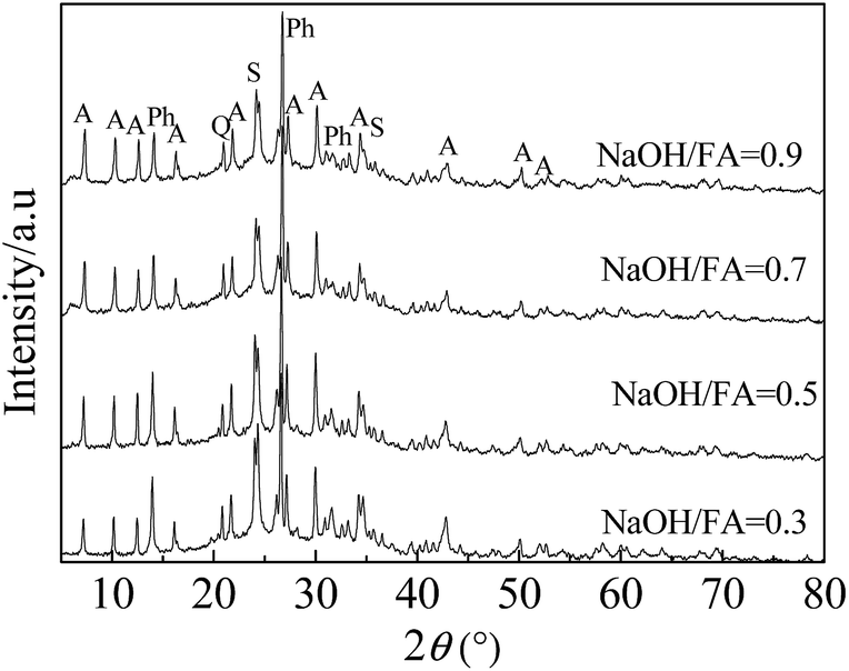
The XRD patterns of the FA zeolites obtained with various alkali–fly ash mass ratios from 0.3 to 0.9 are shown in Fig. 3, and the peaks were consistent with the NaA type characteristic peak at a ratio of 0.5. The effect of the alkali–fly ash ratios on the CEC of ZFA is presented in Fig. 4 and was consistent with the trend; the adsorption capacity was markedly better at an alkali–fly ash mass ratio of 0.5. It is clearly seen that the peak intensities of the NaA zeolite increased as alkali–fly ash ratio was raised and then gradually decreased when the ratio was increased to above 0.9. It is also found that the XRD peak intensity of the NaA zeolite was much lower until the alkali–fly ash ratio was greatly increased to above 0.3. When the ratio was very low (∼0.3 g g−1), only part of the glass phase (mainly mullite and quartz) dissolved in supercritical water. The reactions were more active with the increase of the alkali–fly ash ratio to above 0.3. The glass phase completely disappeared and the dissolution of Si and Al accelerated the zeolite formation.24–26 The results indicated that the high alkali–fly ash ratio led to the fusion of more mullite and quartz in the raw material and the formation of more NaA zeolite. When the alkali–fly ash ratio changed from 0.3 to 0.5, the grain size of mullite and quartz decreased with the increase in the alkali–fly ash ratio, while the size of the crystals generated was gradually enlarged and the crystal form became more complete. But the excess NaOH will restrain the formation of NaA zeolite and promote that of SOD and Ph zeolite.27 A dispersion system of FA and trace water was formed during the solid transformation synthesis process, in which aluminosilicate and adsorbed water were the adsorbent and the adsorbate, respectively. The solid phase system entropy increased significantly due to the dispersion of NaOH powder and the generation of surface bonds on the surface of the aluminosilicate, which led to the formation of an electric field gradient, a potentiometric gradient and a concentration gradient and promoted the self-diffusion of Na+ and OH−,17–19 and aluminosilicate could be depolymerized and rearranged by OH− group.
The XRD patterns of the FA zeolites obtained from various liquid–solid mass ratios are shown in Fig. 5. It can be found that the quartz and mullite phases almost disappeared, and the main crystalline phase of NaA zeolite can be observed at a ratio of 2.5:1. The effect of the liquid–solid mass ratios on the CEC of ZFA is presented in Fig. 6. Increasing the liquid–solid ratios from 2.4 to 3.0 g g−1, caused the CEC values to increase appreciably and then decrease rapidly, with the maximum obtained at 2.7:1 g g−1. The dispersion system of NaOH, FA and trace water could be difficult to form at lower liquid–solid ratios, with aluminosilicate and adsorbed water as the adsorbent and the adsorbate, respectively, and the aluminosilicate could not be depolymerized and rearranged by OH− group. The crystal peak intensity of the NaA zeolite increased as the liquid–solid ratio increased from 2.4:1 to 2.7:1 and then decreased. Furthermore, it can be seen from Fig. 5 that the XRD intensities of quartz and mullite steadily decreased when the liquid–solid mass ratio is increased from 2.4:1 to 2.88:1. The major crystalline phase was SOD at a lower liquid–solid ratio of 2.4:1. A higher liquid–solid ratio could cause low alkalinity and the transformation of NaA zeolite to SOD and Ph zeolites accordingly. Therefore, the appropriate liquid–solid volume ratio is 2.7:1.
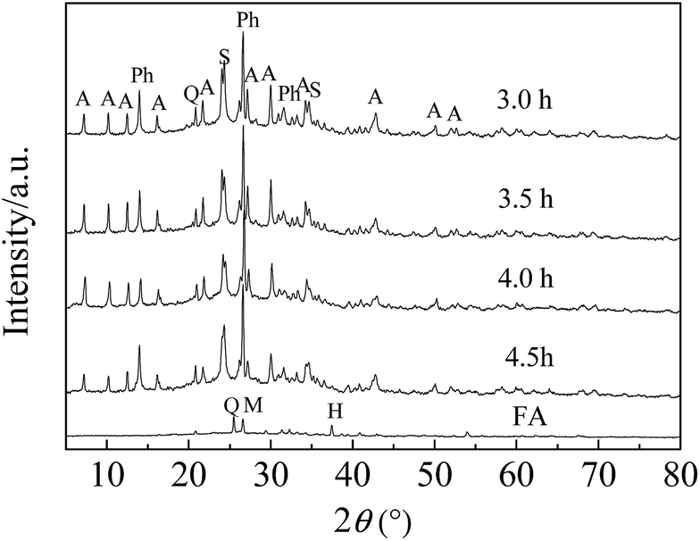
The XRD patterns of FA zeolite synthesized with different crystallization times at 90 °C, with an alkali–fly ash ratio of 0.5:1 and a liquid–solid ratio of 2.7:1 are shown in Fig. 7. It was shown that NaA zeolite was the main crystalline phase with times from 3 to 4.5 h, and the XRD intensities increased with the increase in reaction time, while those of quartz and mullite decreased. The characteristic peaks of NaA zeolite increased gradually with the reaction time. As can be observed in Fig. 8, the adsorption of ZFA increased with the rise of crystallization time and declined rapidly, and the preferable adsorption capacity was attained at 3.5 h. NaA zeolite tends to transform into SOD and Ph zeolite with prolonged reaction times.
Fig. 9 shows the X-ray diffraction patterns of zeolites synthesized from fly ash. According to the diffractograms, the major crystalline phase was identified as NaA zeolite with JCPDS number 43-0142, with small amounts of SOD and Ph zeolite. Quartz normally found in the diffractograms of fly ash could not be completely dissolved during the hydrothermal treatment and remained in the zeolite product after the synthesis. The original fly ash which presented a high content of aluminum, gave rise to the products of three kinds of zeolite (NaA, SOD, and Ph zeolite). Hydroxysodalite zeolite has a high stability under variations of temperature and can be formed during the synthesis of zeolites using coal fly ash as the raw material crystallized between 353.15 K and 413.15 K.28 The amount of Ph zeolite increased with crystallization time and gradually replaced SOD zeolite.23,29
According to the literature, NaA zeolite presents a cubic structure.4,7–10,30 SEM images of fly ash and zeolites synthesized via the solid transformation method, and their EDS analysis can be compared in Fig. 10. Spherical particles with a relatively smooth surface and irregular round shapes predominated in the raw FA shown in Fig. 10(a). The SEM micrographs in Fig. 10(b) and (c) confirm that the major crystalline phase was NaA zeolite, and the minor crystalline phase was Ph and SOD zeolite with rhombic and octahedral crystals, which is consistent with the reported literature.7,23,31,32
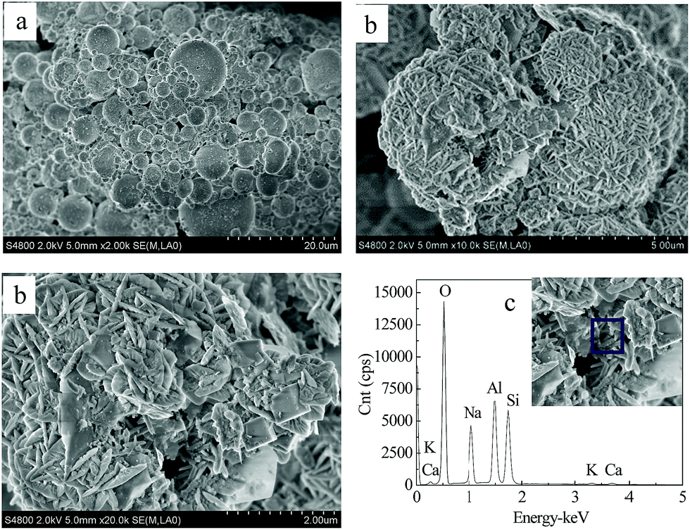 | ||
| Fig. 10 SEM images of fly ash (a) and the crystalline NaA zeolites synthesized from fly ash via the solid transformation method (b). EDS of the synthesized zeolite (c). | ||
Thermal analysis curves (TG and DTA) of the synthesized NaA zeolite are shown in Fig. 11.
 | ||
| Fig. 11 Thermal analysis (TG, DTA) curves of the synthesized NaA zeolite. | ||
An endothermic peak exists in the DTA and the weight loss slope in the TGA curve demonstrates that the maximum rate of H2O loss is at a temperature of around 200 °C. According to the TGA curve, the maximum weight loss, which corresponds to the water content of the sample, is about 12 wt%. The DTA curve of the as-synthesized zeolite shows several thermal effects. The first endothermic effect with its maximum at around 200–250 °C is relevant to the water released from the NaA zeolite,9 accompanied by a sharp and sudden loss of mass. It seems that an exothermic effect at 500–540 °C may be connected with the partial decomposition of the NaA zeolite structure. Usually a process of crystal decomposition is exothermic in character. Moreover, in certain cases it has been reported that the decomposition of zeolites is related to the collapse of free duct spaces at this temperature.
The chemical composition of ZFA is shown in Table 1. Silica, alumina, iron oxide, sodium oxide and calcium oxide are the main chemical components. A significant amount of Na element is incorporated in the final product due to the hydrothermal treatment with solid NaOH. Due to the dissolution of SiO2 during the hydrothermal treatment, the amount of this compound in ZFA decreased. The SiO2/Al2O3 mole ratio of 2.13 for the ZFA product is close to that of a NaA (NaAlSiO4.2·2.25H2O, SiO2/Al2O3 2.0) type zeolite.
The specific surface area was measured using the BET method. Fig. 12 and Table 2 show that the specific surface area, cation exchange capacity (CEC) and total pore volume of the synthesized hybrid (NaA, SOD, and Ph) zeolites are 14.48 m2 g−1, 253.86 mmol/100 g and 0.035 cm3 g−1, respectively. These values are in accordance with the data found in the literature.4,19,23,27 The isotherms can be categorized as type I, indicating the existence of microporous materials. Generally the NaA type zeolite products had micropore structures with one broad capillary condensation step at a p/p0 value of 0.05–0.95, representing the broad pore size distribution normally observed with NaA type zeolites.
 | ||
| Fig. 12 N2 sorption isotherms of NaA ZFA. | ||
| Sample | SBET (m2 g−1) | CEC (mmol/100 g) | Total pore volume (cm3 g−1) | Average pore size (nm) |
|---|---|---|---|---|
| a ZFA: zeolite synthesized from fly ash via the solid transformation method. This work.b NaA: zeolite synthesized from fly ash via the alkaline fusion method. Our team.c NaA: zeolite synthesized from fly ash via the alkaline fusion method (ref. 27). | ||||
| FA | 9.9 | 15.6 | 0.016 | 15.3 |
| CZ | 17.66 | 279.31 | 0.050 | 0.30 |
| ZFAa | 14.48 | 253.86 | 0.035 | 0.49 |
| NaAb | 16.12 | 357.31 | 0.028 | 0.34 |
| NaAc | 41.2 | 400.0 | ||
| NaAc | 36.1 | 377.0 | ||
It is clearly shown that the BET surface area, CEC and total pore volume are 81.99%, 90.89%, and 70.0% that of commercial NaA zeolite, respectively, and are higher than that of the raw fly ash. The CEC values presented by the pure NaA type zeolites synthesized from FA via the alkaline fusion method are higher than those of the hybrid materials produced in the current study,27 while the CEC value of ZFA in our work is much higher than that of the products synthesized using a one-step hydrothermal treatment (Fig. 13).15
 | ||
| Fig. 13 XRD patterns of FA, CZ and NaA ZFA synthesized using the alkaline fusion method and an SEM image of the NaA ZFA synthesized by our team. | ||
The characteristics and adsorption capacity of ZFA synthesize via the solid transformation method were investigated in comparison to those of FA, commercial zeolite (CZ), and NaA ZFAs reported in related references, and the test to remove Cr(VI) from an aqueous solution was conducted at pH 3.12 under the same conditions. According to Fig. 14, the rate of uptake of Cr(VI) was quite rapid; at equilibrium, the time-dependent amounts of Cr(VI) adsorbed were 2.1 mg g−1 for FA, 7.6–8.7 mg g−1 for the ZFAs and 8.7 mg g−1 for CZ, which indicated that the ZFA was much more effective than FA, and was similar to CZ, and the zeolites synthesized from fly ash were found to successfully remove Cr(VI) from an aqueous solution. The adsorption capacity and CEC value of NaA synthesized using the alkaline fusion method in our team were as good as those of the NaA commercial zeolite, and were superior to those ZFA synthesized via the solid transformation in this work. This could be due to the SOD and Ph zeolite in this hybrid material.
 | ||
| Fig. 14 Efficiency of Cr(VI) removal by FA, the commercial NaA zeolite and the zeolite synthesized by FA, C0 = 50.26 mg l−1, pH = 3.12, dosage = 5 g l −1, T = 25 °C. aZFA: zeolite synthesized from fly ash via the solid transformation method. This work. bNaA ZFA: zeolite synthesized from fly ash via the alkaline fusion method. Our team. cNaA ZFA: zeolite synthesized from fly ash via the alkaline fusion method (ref. 26). | ||
Conclusions
NaA zeolite (with small amounts of SOD and Ph zeolite) was converted from FA by means of a solid transformation method in a trace water system. Results revealed that a mixture of FA and NaAlO2 with the molar ratio of SiO2/Al2O3 of 2.2 can be converted to NaA zeolite at a calcination temperature and time of 650 °C and 60 min, an alkali–fly ash ratio of 0.5:1, a crystallization temperature and time 90 °C and 3.5 h, and a liquid–solid ratio of 2.7:1. It is easy to form NaA zeolite. The synthesized FA zeolites can be well used as sorbents for the removal of Cr(VI) from an aqueous solution. The formation of NaA zeolite was ascertained by means of different characterization techniques including XRF, XRD, SEM, TGA/DTA, and BET. The XRD results revealed that the major crystalline phase was identified as NaA zeolite, with small amounts of SOD and Ph zeolite. The morphology of the synthesized product also indicated the cubic structure crystal of NaA, and the minor crystalline phase had rhombic, octahedral and cubic crystals. The results were confirmed using CEC and BET techniques. The CEC and specific surface area of NaA were 253.86 mmol/100 g and 14.18 m2 g−1, respectively.
Acknowledgements
This work was supported by the National Natural Science Foundation of China (21277093), Program for New Century Excellent Talents in University (NCET-13-0910), General Project of Liaoning Provincial Department of Education (L2015361), Liaoning BaiQianWan Talents Program (2014921003), the Science and Technology Program of Shenyang City of China (F13-062-2-00) and the Competitive Selection Project of Shenyang Scientific Undertaking.References
- M. Ahmaruzzaman, Prog. Energy Combust. Sci., 2010, 36, 327 CrossRef CAS.
- S. S. Bukhari, J. Behin, H. Kazemian and S. Rohani, Fuel, 2015, 140, 250 CrossRef CAS.
- H. Holler and U. Wirsching, Fortschr. Mineral., 1985, 63, 21 Search PubMed.
- J. C. Izidoro, D. A. Fungaro, J. E. Abbott and S. Wang, Fuel, 2013, 103, 827 CrossRef CAS.
- H. Tanaka and A. Fujii, Adv. Powder Technol., 2009, 20, 473 CrossRef CAS.
- B. Jha and D. N. Singh, Appl. Clay Sci., 2014, 90, 122 CrossRef CAS.
- M. Zhang, H. Zhang, D. Xu, L. Han, D. Niu, L. Zhang, W. Wu and B. Tian, Desalination, 2011, 277, 46 CrossRef CAS.
- J. Wang, D. Li, F. Ju, L. Chang and W. Bao, Fuel Process. Technol., 2015, 96, 136 Search PubMed.
- H. Kazmian, Z. Naghdali, T. G. Kashani and F. Farhadi, Adv. Powder Technol., 2010, 21, 279 CrossRef.
- W. Franus, Pol. J. Environ. Stud., 2012, 21(2), 337 CAS.
- M. Wdowin, M. M. Wiatros-Motyka, R. Panek, L. A. Stevens, W. Franus and C. E. Snape, Fuel, 2014, 128, 451 CrossRef CAS.
- W. Franus, M. Wdowin and M. Franus, Environ. Monit. Assess., 2014, 186(9), 5721 CrossRef CAS PubMed.
- L. Bandura, M. Franus, G. Józefaciuk and W. Franus, Fuel, 2015, 147, 100 CrossRef CAS.
- C. Belviso, F. Cavalcante, F. J. Huertas, A. Lettino, P. Ragone and S. Fiore, Microporous Mesoporous Mater., 2012, 162, 115 CrossRef CAS.
- N. M. Musyoka, L. F. Petrik, E. Hums, H. Baser and W. Schwieger, Catal. Today, 2012, 190, 38 CrossRef CAS.
- A. M. Cardoso, M. B. Horn, L. S. Ferret, C. M. N. Azevedo and M. Pires, J. Hazard. Mater., 2015, 287, 69 CrossRef CAS PubMed.
- Y. Liu, D. Li and X. Wang, China Surfactant Deterg. Cosmet., 2002, 32, 53 CAS.
- S. Catidge and W. M. Meier, Zeolites, 1984, 4, 218 CrossRef.
- R. Tsai, K. Du, T. Cheng, G. H. Ho, P. Wu, S. Liu and T. Tsai, Catal. Today, 2013, 204, 30 CrossRef CAS.
- C. Ferone, B. Liguori, A. Marocco, O. Omotoso, W. Friesen, C. Fairbridge, Y. Shi and S. Ng, Microporous Mesoporous Mater., 2010, 134, 65 CrossRef CAS.
- J. H. Zhang, M. B. Yue, X. N. Wang and D. Qin, Microporous Mesoporous Mater., 2015, 217, 98 CrossRef.
- H. Feng, X. Chen, H. Shan and J. W. Schwank, Catal. Commun., 2010, 11, 700 CrossRef CAS.
- J. C. Izidoro, D. A. Fungaro, F. S. Santos and S. Wang, Fuel Process. Technol., 2012, 97, 38 CrossRef CAS.
- M. Lee, G. Yi, B. Ahn and F. Roddick, Korean J. Chem. Eng., 2000, 17, 325 CrossRef CAS.
- H. Tanaka, S. Matsumura and R. Hino, J. Mater. Sci., 2004, 39, 1677 CrossRef CAS.
- S. H. Asl, M. Ahmadi, M. Ghiasvand, A. Tardast and R. Katal, J. Ind. Eng. Chem., 2013, 19, 1044 CrossRef CAS.
- M. Chareonpanich, O. Jullaphan and C. Tang, J. Cleaner Prod., 2011, 19, 58 CrossRef CAS.
- C. Poole, H. Prijatama and N. M. Rice, Miner. Eng., 2000, 13, 831 CrossRef CAS.
- Q. Xavier, A. Andres, L. Jose, T. Fernandez and L. S. Angel, Fuel, 1995, 74(8), 1226 CrossRef.
- R. Panek, M. Wdowin and W. Franus, in International Multidisciplinary Microscopy Congress, Springer International Publishing, 2014, vol. 45 Search PubMed.
- G. Atun, G. Hisarh, A. E. Kurtoglu and N. Ayar, J. Hazard. Mater., 2011, 187, 562 CrossRef CAS PubMed.
- N. Koukouzas, C. Vasilatos, G. Itskos, I. Mitsis and A. Moutsatsou, J. Hazard. Mater., 2010, 173, 581 CrossRef CAS PubMed.
| This journal is © The Royal Society of Chemistry 2015 |