 Open Access Article
Creative Commons Attribution 3.0 Unported Licence
Synthesis of silver nanoparticles in a microfluidic coaxial flow reactor†
Razwan
Baber
a,
Luca
Mazzei
a,
Nguyen T. K.
Thanh
bc and
Asterios
Gavriilidis
*a
aDepartment of Chemical Engineering, University College London, UK. E-mail: a.gavriilidis@ucl.ac.uk
bUCL Healthcare Biomagnetic and Nanomaterials Laboratories, UK
cBiophysics Group, Department of Physics and Astronomy, University College London, UK
First published on 6th November 2015
Abstract
The size and dispersity of nanoparticles (NPs) determine the properties that such particles display. In this study, synthesis of silver nanoparticles in a coaxial flow reactor (CFR) was investigated by confining the reaction and subsequent nucleation to an interface away from the channel wall. Silver NPs were formed at room temperature by reducing silver nitrate with sodium borohydride in the presence of sodium hydroxide, while trisodium citrate was used as the surfactant. The main parameters investigated were flow rate of reagents through the CFR and concentrations of trisodium citrate and silver nitrate. Decreasing the total flow rate resulted in the NP size and dispersity reducing from 5.4 ± 3.4 nm to 3.1 ± 1.6 nm. Increasing surfactant concentration reduced size and dispersity from 8.5 ± 6.9 nm to 4.1 ± 1.1 nm. By tuning the precursor concentration the size and dispersity could be reduced from 9.3 ± 3 nm to 3.7 ± 0.8 nm.
Introduction
Silver nanoparticles (NPs) are used in many applications, such as gas sensors,1,2 optics,3–5 electronics,6,7 catalysis8,9 and biomedicine.10,11 The properties relevant for these applications depend strongly on the size of the particles. Therefore, monodispersity of synthesized NPs is of paramount importance. Microfluidic devices have been employed to synthesize NPs because of the various benefits that they offer,12,13 including improved heat and mass transfer, increased efficiency and safety.14 Another benefit of using microfluidic processes, as opposed to conventional batch reactors, is the spatiotemporal separation of the various stages of the synthesis including reaction, nucleation and growth, which enables a greater control over size, shape, composition and size distribution of the NPs.15–17 It also allows for an increased flexibility in analysing the mechanisms of each of these stages.18–20 These benefits arise from small channel widths, high surface area to volume ratios and small overall volumes. The disadvantage of using reactors with a high surface area to volume ratio is that there is a higher chance of fouling and accumulation of material on the walls of the channel. Hence, microreactors which are not easily susceptible to accumulation of material on their walls are desirable. There are various studies which implemented different strategies to avoid fouling, such as the segmented-flow approach and the reduction of wall interactions through pH alteration and surface silanization of the channel walls.21–23 One type of design that alleviates the occurrence of fouling is the coaxial flow reactor (CFR) which allows an inner stream of reagent to be surrounded by an outer stream, creating a reaction interface between the streams.15,16,24–28 The CFR is less susceptible to fouling because the reduction of precursor ions and nucleation of metal NPs occur at the interface between the inner and outer streams, rather than near the channel walls. This reduction in fouling relies on the flow profile of the channel remaining in a stable laminar regime. This has adverse effects with regards to mixing efficiency, unless a reduction of diffusion distances or sufficient contact time is applied.Examples of CFRs are found in the studies by Takagi et al. who produced titania NPs using an axial dual-pipe microdevice.24 Using various flow conditions and tuning of solvent properties such as viscosity and surface tension, the flow characteristics in their device were tuned and led to increased control over mass transfer. The mass transfer of the reagents in the microdevice determined the size and monodispersity of the NPs which was demonstrated by using different solvent types, tube diameters and precursor concentrations. Maki et al. employed a concentric-axle dual-pipe microreactor to synthesise zirconia NPs,25 and showed that increasing residence time resulted in larger NPs. Abou Hassan et al. used a coaxial flow device operated under laminar flow conditions to synthesise iron oxide, goethite and Fe2O3@SiO2 core/shell NPs.15,16,26 7 nm iron oxide NPs were synthesized in the coaxial flow device and polydispersity decreased from 35% in a typical batch synthesis to ca. 20% in the coaxial flow device.26 Goethite NPs were synthesized using the coaxial flow device as a nucleation section before a long residence loop in a temperature controlled bath. The goethite NPs were produced with a residence time of around 15 min as opposed to several hours using traditional batch methods, and were also smaller than those made in batch vessels.15 Similarly, a multistep approach using the coaxial flow devices was used to synthesise Fe2O3@SiO2 core/shell NPs within a much shorter timescale as compared to batch.16 Lim et al. operated a CFR in the turbulent regime to produce various NPs such as iron oxide with an ability to tune the size through changing the flow conditions.27 Schülein et al. used a micro coaxial-injection flow mixer for the synthesis of nickel NPs. The process for synthesising nickel NPs quickly blocked commercially available microstructured mixers and the coaxial-injection mixer was used in a pilot plant scale process mainly because it could avoid fouling and blockage issues.28
Synthesis of silver NPs using silver nitrate, sodium borohydride (with sodium hydroxide) and trisodium citrate in a coaxial flow reactor in this study has not been reported in the literature. Shirtcliffe et al. reported the synthesis of silver nanoparticles using sodium borohydride and sodium hydroxide as a reducing agent for silver nitrate using a PTFE flow chamber and also using Eppendorf pipettes to mix reagents directly into plastic cuvettes.29 Wagner et al. synthesized silver NPs in a split and recombine mixer using borohydride as a reducing agent for silver nitrate and despite fouling were able to control the size of the NPs by tuning the borohydride ratio, obtaining NPs in the range of 10–20 nm for borohydride to silver nitrate ratios ranging from 3 to 40.30 Further studies using borohydride as a reducing agent for the reduction of a silver precursor to form silver NPs in the aqueous phase were mainly in batch reactors with NP sizes ranging between 1 and 100 nm.31–34
The main objective of this work is to study how the size and monodispersity of silver NPs can be controlled by changing the operating parameters of flow rate and concentration of ligand (trisodium citrate) and precursor (silver nitrate). The motivation for using a CFR was to avoid fouling issues and blockages, an issue which was encountered when synthesising NPs using the same chemical system in a split and recombine type micromixer (see ESI Fig. S1† for images of fouling in such micromixer).
Experimental
Chemicals
Silver nitrate (AgNO3, 0.01 M stock solution), trisodium citrate (HOC(COONa)(CH2COONa)2·2H2O, powder form) and sodium borohydride solution (NaBH4, ∼12 wt% in 14 M NaOH stock solution), were obtained from Sigma Aldrich Company Ltd., UK. All chemicals were used without further purification and solutions were prepared with ultrapure water (resistivity 15.0 MΩ cm) and diluted to the desired concentrations before being introduced into the CFR.Experimental setup
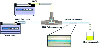
Syringe pumps (Pump 11 Elite OEM Module, Harvard Apparatus) were used in the experiments to deliver the two streams of silver nitrate/trisodium citrate solution and sodium borohydride solution to the CFR. The CFR used in this study consisted of a small inner tube which was inserted into the centre of a larger outer tube (Fig. 1). Both the inner and outer tubes were made of glass and inner tubes of two different internal channel diameters of 0.556 mm and 0.798 mm were used in separate experiments. The outer tube had an internal channel diameter of 2 mm. The distance from the inner tube outlet to the outlet of the CFR was 130 mm. The capillaries were connected together using a T-piece connector (0.508 mm thru-hole, Upchurch Scientific) which was drilled to a size of 2 mm internal diameter (I.D.) to allow the inner tube to be inserted into the outer tube. The flow ratio between the inner and outer stream, Qout![[thin space (1/6-em)]](https://www.rsc.org/images/entities/char_2009.gif) :
:![[thin space (1/6-em)]](https://www.rsc.org/images/entities/char_2009.gif) Qin, was fixed at 1
Qin, was fixed at 1![[thin space (1/6-em)]](https://www.rsc.org/images/entities/char_2009.gif) :
:![[thin space (1/6-em)]](https://www.rsc.org/images/entities/char_2009.gif) 1 and the CFR operated in the laminar flow regime for all experiments.
1 and the CFR operated in the laminar flow regime for all experiments.
Synthesis of silver nanoparticles
A typical synthesis was as follows: silver nitrate and trisodium citrate were mixed together in solution and introduced via the inner tube of the CFR, while the sodium borohydride solution was introduced via the outer tube of the reactor. Fresh trisodium citrate solution was made by dissolving the powder in ultrapure water before each synthesis. All reactions were carried out at room temperature (typically between 22 and 24 °C). All concentrations, unless otherwise stated, are concentrations of the individual streams being introduced into the CFR. Since the sodium borohydride was stored in 14 M sodium hydroxide, the concentration of sodium hydroxide was 3.21 times higher than the stated sodium borohydride concentration in all cases.The literature shows that borohydride can supply up to eight molar equivalents of electrons to reduce the silver ions to silver metal.35–37 The amount of electrons released from the borohydride molecule depends on whether the formed H+ ions react with H− ions from the molecule to form hydrogen gas, which would limit the electrons available for reducing metal ions. Highly basic conditions reduce the formation of hydrogen gas hence freeing up more electrons for reduction of the metal ion. In this study sodium borohydride was stored and used under basic conditions which should produce a higher amount of electrons for reducing the metal ions. Samples were stored for months without noticeable formation of hydrogen bubbles whereas when sodium hydroxide was not used to arrest the hydrolysis reaction, hydrogen bubbles formed within the samples after a short time. The actual amount of electrons utilized to reduce silver is unknown, though it is suggested by Shirtcliffe et al. that six of the available eight electrons are utilized to reduce silver ions under basic conditions.29
The primary purpose of sodium borohydride is to reduce the silver ions to silver metal; however, it also affects the growth of the NPs. The surface charge of the particles is affected by borohydride and hydroxide ion adsorption and it is well established that the conversion of borohydride to borate in aqueous solution results in changes in the particle charge.38,39 Under basic conditions the conversion of borohydride slows down.40,41 However, trisodium citrate is used as the primary stabilising agent in this study. The concentrations of the reducing agent (sodium borohydride) and ligand (trisodium citrate) in relation to the precursor concentration (silver nitrate) determine the nucleation, growth and stabilisation of the NPs. Since the concentration is important in determining the size and dispersity of resultant NPs, the mass transfer during the reaction becomes important as this dictates the concentration at which the reaction takes place at any given time during the reaction. The reproducibility of the synthesis in the CFR over a range of flow rates was assessed by repeating the synthesis 4 times for each flow rate (Fig. S2 in ESI† shows UV-vis analysis of the repeated syntheses).
Characterisation of nanoparticles
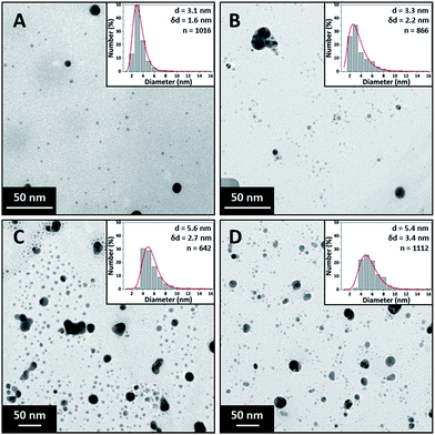
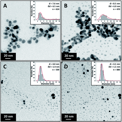
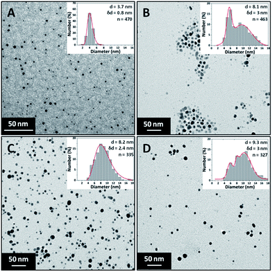
The silver NPs were analysed within an hour of the synthesis using a UV-vis spectrometer (USB 2000+ Spectrometer and DT-Mini-2-GS light source, Ocean Optics). Transmission electron microscope (TEM) images were captured using a JEOL 1200 EX II microscope with a 120 kV acceleration voltage. Carbon coated copper TEM grids were prepared within an hour of synthesis by pipetting a 15 μl sample onto the grid and allowing it to dry at room temperature. The TEM images have in the inset particle size distributions, average diameter, d, standard deviation, δd, indicating polydispersity and number of particles counted to obtain the particle size distribution, n.Results and discussion
Effect of total flow rate on NP size and polydispersity
Experiments were carried out in the CFR with an inner tube channel diameter of 0.798 mm at various flow rates. The CFR was used to synthesize silver NPs at concentrations of 0.2 mM silver nitrate, 0.2 mM trisodium citrate and 0.6 mM sodium borohydride at total flow rates ranging from 1 ml min−1 to 14 ml min−1. The mole ratio of sodium borohydride to silver nitrate is 3![[thin space (1/6-em)]](https://www.rsc.org/images/entities/char_2009.gif) :
:![[thin space (1/6-em)]](https://www.rsc.org/images/entities/char_2009.gif) 1, but the ratio of electrons to silver ions is many times greater than this.
1, but the ratio of electrons to silver ions is many times greater than this.
Fig. 2 shows TEM images of silver NPs synthesised at 1 ml min−1, 2.5 ml min−1, 8 ml min−1 and 14 ml min−1 along with their respective particle size distributions. The particle size synthesised at the lower flow rates of 1 ml min−1 (3.1 ± 1.6 nm) and 2.5 ml min−1 (3.3 ± 2.2 nm) are statistically smaller than those at the higher flow rates of 8 ml min−1 (5.6 ± 2.7 nm) and 14 ml min−1 (5.4 ± 3.4 nm) while the polydispersity steadily increases from ±1.6 nm to ±3.4 nm. However, the particle sizes at 8 ml min−1 and 14 ml min−1 were not found to be statistically different using a t-test (p = 0.209).
According to Mie theory, for NPs in the range between 6 and 10 nm the peak absorbance increases with size (for a given concentration) but the peak wavelength does not shift significantly.42 From the UV-vis analysis (see ESI, Fig. S3†), the peak wavelength does not change significantly (between 392 and 393 nm for all flow rates) in agreement with theory. However the peak absorbance of the spectra decreases minimally from 1.35 to 1.27 (statistically different, p < 0.01) with increasing flowrate even though TEM shows an increasing average size of NPs from 3.1 nm to 5.4 nm. This can be explained by the increased polydispersity observed at higher flow rates where NPs larger than 10 nm are formed. This results in increased full width at half maximum of the resonance peaks at higher flow rates, and since the mass of silver used in each experiment is constant, the peak absorbance decreases.
The concentrations of precursor, reducing agent and ligand are important factors in controlling nucleation and growth and hence size of the synthesised NPs. The evolution of the concentration profiles along the length of the reactor is controlled by mass transfer, i.e. the mixing characteristics. Mixing in the CFR occurs by diffusion, since it operates in the laminar flow regime for the flow rates employed. We can use a simple relationship:43
Literature suggests that reaction and nucleation in silver NP synthesis have very fast kinetics evidenced by the timescales of nanoparticle appearance in studies by Polte et al. which suggests reduction occurs in less than 200 ms,39 and Takesue et al. in which nucleation is observed in less than 1 ms.46 Thus, the reaction is likely to occur at or very close to the interface between the two streams, at least in the initial part of the reactor and at high flowrates. The inner and outer streams behave as reservoirs of precursor and reducing agent respectively which supply the necessary reagents at the interface region for reduction of silver ions to silver metal and subsequent clustering and stabilisation. Comparing the average residence times with characteristic times for diffusion, we can conclude that at high residence time (24.5 s) most of the silver nitrate in the inner stream would be consumed, because of the fast kinetics and sufficient diffusion time of the borohydride (36 s). This is likely not to be the case at low residence time (1.75 s).
Higher flow rates resulted in the appearance of larger silver NPs. This may be rationalised as follows. The reaction occurring at the interface within the CFR results in silver atoms being formed in that region. The concentration of silver atoms increases until they form clusters (synthesis mechanisms in the literature strongly suggest that the metal atoms form clusters which coalesce to form small nanoparticles).39,46,47 A smaller amount of silver precursor is consumed and smaller amounts of clusters are formed within the CFR at low residence time. A higher amount of silver nitrate is left unreacted at the outlet of the CFR, where droplets form and mixing and consumption of reagents continue within them. Mixing there is through recirculation patterns as the droplets form. Even though these convective patterns promote faster mass transfer than diffusion, they result in non-homogenous concentration areas. Thus, the larger amount of remaining silver ions reacts and moves to areas where the concentration of silver nitrate may be high relative to borohydride. The resultant NPs would have a lower surface charge because of the low amount of borohydride ions which adsorb onto their surface. This in turn allows the NPs to aggregate and grow to a larger size, since it is established that a decrease of surface charge of the NPs (most likely because of borohydride ion depletion) causes NPs to grow to a larger size.38 The appearance of higher amount of larger NPs, further gives rise to the increased polydispersity observed.
An interesting observation was that a layer of silver formed on the inner wall near the outlet of the inner tube through which the silver nitrate was flowing. This fouling occurred on the outer wall of the inner tube when silver nitrate was flowing through the outer tube. Fouling only occurred on the side of the inner tube where silver nitrate was flowing i.e. a silver nitrate rich zone (see Fig. S4 and S5 in ESI† for images of fouling on the channel walls). The reason fouling did not occur on the sodium borohydride side during experiments may be because silver metal atoms produced in sodium borohydride rich zones would have a high negative surface charge and hence cannot grow and deposit on the negatively charged glass channel wall in the sodium borohydride stream.48 This is consistent with the larger NPs obtained at higher flow rates, which increases the polydispersity. Another point to note is that citrate molecules were also available in the silver nitrate stream, but they did not prevent the deposition of silver metal on the inner tube.
Effect of citrate concentration on NP size and polydispersity
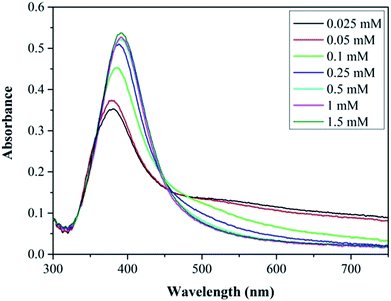
The effect of surfactant concentration on the NP morphology was investigated by varying the trisodium citrate concentration. The silver nitrate and sodium borohydride concentrations were kept constant at 0.1 mM and 0.3 mM respectively. The role of sodium borohydride and why it was in such high excess was discussed previously. Trisodium citrate concentration was varied between 0.025 mM and 1.5 mM. Due to these high citrate concentrations, the silver nitrate and sodium borohydride concentration was reduced (though still using a 3 to 1 ratio of sodium borohydride to silver nitrate) to keep the ionic strength as low as possible. The flow rate of each stream was 1.25 ml min−1 making a total flowrate of 2.5 ml min−1. Fig. 3 shows TEM images and particle size distribution of the silver NPs synthesized at various citrate concentrations (0.025 mM to 0.75 mM) with average diameter and standard deviation for each concentration. It can be seen that the polydispersity and average size of the NPs decreases with increasing citrate concentration because of the reduction in the amount of large fused NPs present.Fig. 4 shows the UV-vis spectra of the silver NP samples for each citrate concentration tested. The resonance peaks at lower citrate concentration are characterised by a lower plasmon peak absorbance and a higher absorbance at longer wavelengths; and as the citrate concentration is increased up to 0.25 mM the plasmon peak increases and the peak at higher wavelengths is reduced. The tail in the resonance peak is indicative of the presence of larger fused NPs, as confirmed by TEM imaging at lower citrate concentrations, suggesting citrate plays a key role in reducing formation of larger fused NPs. Increasing the concentration of citrate above 0.5 mM up to 1.5 mM does not alter the synthesised silver NP characteristics. This shows that a minimum citrate concentration is needed to obtain relatively monodispersed NPs and to prevent the formation of larger fused NPs with irregular shapes. Henglein and Giersig also showed in a study using radiolysis for the reduction of AgClO4 that larger fused NPs were formed when insufficient amounts of citrate were used (they also showed large fused NPs when the citrate concentration was too high).49
Effect of silver nitrate concentration on NP size and polydispersity
The effect of precursor concentration on the NP size and polydispersity was investigated by varying the concentration of silver nitrate. The trisodium citrate and sodium borohydride concentrations were kept constant at 0.5 mM and 0.3 mM respectively. The silver nitrate concentration was varied between 0.05 mM and 0.4 mM. Sodium borohydride is expected to reduce all silver ions even at the highest precursor concentration used since it is expected to supply an excess of electrons for reduction. The flow rate of each stream was 1.25 ml min−1 making a total flowrate of 2.5 ml min−1. The Beer–Lambert law applied for synthesised Ag NPs having peak absorbance values below 1.5. Therefore, samples were diluted if the absorbance was above this value for normalisation.Fig. 5 shows TEM images of the silver NPs along with their respective particle size distributions. The size increased from 3.7 ± 0.8 nm to 9.3 ± 3 nm with increasing silver concentration. It can be seen that small and relatively monodisperse NPs form at the lowest concentration with a transition into a more polydisperse bimodal distribution occurring at 0.15 mM silver nitrate. The higher polydispersity may be related to a larger extent of reduction taking place in the droplets at the exit of the CFR, as discussed earlier.
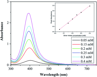
Fig. 6 shows the UV-vis spectra for each synthesis carried out at various silver nitrate concentrations. The peak absorbance increases with increasing concentration showing a linear dependence. The increase is most likely because of a higher concentration of NPs and increased average size of the NPs (absorbance increases with size for NPs below 10 nm).42
As discussed previously, high amounts of silver nitrate in the droplets forming at the outlet of the CFR can lead to silver nitrate rich zones (due to imperfect mixing) which lead to larger NPs forming (as well as increased polydispersity). In the case of the lowest silver nitrate concentration (0.05 mM) there is a low amount of silver nitrate in the droplets at the outlet of the CFR, leading to a lower possibility of silver nitrate rich zones. At higher silver nitrate concentrations there is a larger amount within the droplets at the outlet of the CFR, increasing the likelihood of reactions occurring in silver nitrate rich zones leading to an increased formation of larger NPs and polydispersity.
Conclusions
The performance of a Coaxial Flow Reactor (CFR) was investigated for silver nanoparticle synthesis. The reaction was confined to the interface between the inner and outer streams resulting in the generation of silver clusters which increase in concentration along the length of the CFR. Hence the residence time is an important parameter which determines the amount of the precursor consumed before the advective mixing within the droplets at the end of the CFR. Residence time determines the amount of silver nitrate consumed in the CFR, and it is shown that shorter residence times where less silver nitrate is consumed, results in larger NPs being formed. This is possibly because reactions in silver nitrate rich zones (i.e. reactor outlet at high flow rates) lead to the formation of NPs with low surface charge which have reduced stability and hence have a tendency to grow by coalescence. For the same reason, increasing silver nitrate concentration, while maintaining a constant residence time resulted in an increase of NP size and polydispersity. Increasing citrate concentration reduced the amount of larger fused NPs resulting in a smaller average size and reduced polydispersity. Such fused NPs disappeared above a citrate concentration of 0.25 mM. Increasing the concentration of citrate past this amount did not decrease the size of the NPs further, indicating that a threshold is reached. The CFR offers a simple method to control the size of the NPs because of its unique design. By keeping advective mixing to a minimum, the reaction is maintained at the interface region between the two streams. This avoids the problem of blockage of the channels by containing the reaction away from the channel walls, unlike other types of microfluidic devices where the reaction can take place close to the channel walls.Acknowledgements
The authors would like to thank EPSRC and University College London for funding. NTK Thanh thanks The Royal Society for her University Research Fellowship.Notes and references
- G. Korotcenkov, B. K. Cho, L. B. Gulina and V. P. Tolstoy, Sens. Actuators, B, 2012, 166–167, 402–410 CrossRef CAS.
- N. Bahadur, K. Jain, R. Pasricha, Govind and S. Chand, Sens. Actuators, B, 2011, 159, 112–120 CrossRef CAS.
- D. D. Evanoff and G. Chumanov, ChemPhysChem, 2005, 6, 1221–1231 CrossRef CAS PubMed.
- S. Panigrahi, S. Praharaj, S. Basu, S. K. Ghosh, S. Jana, S. Pande, T. Vo-Dinh, H. Jiang and T. Pal, J. Phys. Chem. B, 2006, 110, 13436–13444 CrossRef CAS PubMed.
- C. J. Murphy, T. K. Sau, A. M. Gole, C. J. Orendorff, J. Gao, L. Gou, S. E. Hunyadi and T. Li, J. Phys. Chem. B, 2005, 109, 13857–13870 CrossRef CAS PubMed.
- D. Chen, X. Qiao, X. Qiu and J. Chen, J. Mater. Sci., 2009, 44, 1076–1081 CrossRef CAS.
- Y. Li, Y. Wu and B. S. Ong, J. Am. Chem. Soc., 2005, 127, 3266–3267 CrossRef CAS PubMed.
- A. C. Patel, S. Li, C. Wang, W. Zhang and Y. Wei, Chem. Mater., 2007, 19, 1231–1238 CrossRef CAS.
- S. Link, Z. L. Wang and M. El-Sayed, J. Phys. Chem. B, 1999, 103, 3529–3533 CrossRef CAS.
- G. A. Sotiriou and S. E. Pratsinis, Curr. Opin. Chem. Eng., 2011, 1, 3–10 CrossRef CAS PubMed.
- V. K. Sharma, R. A. Yngard and Y. Lin, Adv. Colloid Interface Sci., 2009, 145, 83–96 CrossRef CAS PubMed.
- C.-X. Zhao, L. He, S. Z. Qiao and A. P. J. Middelberg, Chem. Eng. Sci., 2011, 66, 1463–1479 CrossRef CAS.
- S. Marre and K. F. Jensen, Chem. Soc. Rev., 2010, 39, 1183–1202 RSC.
- A. Gavriilidis, P. Angeli, E. Cao, K. K. Yeong and Y. S. S. Wan, Chem. Eng. Res. Des., 2002, 80, 3–30 CrossRef CAS.
- A. Abou-Hassan, O. Sandre, S. Neveu and V. Cabuil, Angew. Chem., Int. Ed., 2009, 48, 2342–2345 CrossRef CAS PubMed.
- A. Abou-Hassan, R. Bazzi and V. Cabuil, Angew. Chem., Int. Ed., 2009, 48, 7180–7183 CrossRef CAS PubMed.
- S. A. Khan, A. Günther, M. A. Schmidt and K. F. Jensen, Langmuir, 2004, 20, 8604–8611 CrossRef CAS PubMed.
- X. Shen, Y. Song, S. Li, R. Li, S. Ji, Q. Li, H. Duan, R. Xu, W. Yang and K. Zhao, RSC Adv., 2014, 4, 34179–34188 RSC.
- R. Wang, W. Yang, Y. Song, X. Shen, J. Wang, X. Zhong, S. Li and Y. Song, Sci. Rep., 2015, 5, 9189 CrossRef PubMed.
- W. Chen-Hsun, H. Chih-Chia, Y. Chen-Sheng, L. Huan-Yao and L. Gwo-Bin, J. Micromech. Microeng., 2008, 18, 035019 CrossRef.
- A. Knauer, A. Csáki, F. Möller, C. Hühn, W. Fritzsche and J. M. Köhler, J. Phys. Chem. C, 2012, 116, 9251–9258 CAS.
- A. Knauer, A. Thete, S. Li, H. Romanus, A. Csaki, W. Fritzsche and J. M. Koehler, Chem. Eng. J., 2011, 166, 1164–1169 CrossRef CAS.
- J. Wagner and J. M. Kohler, Nano Lett., 2005, 5, 685–691 CrossRef CAS PubMed.
- M. Takagi, T. Maki, M. Miyahara and K. Mae, Chem. Eng. J., 2004, 101, 269–276 CrossRef CAS.
- T. Maki, J. I. Kitada and K. Mae, Chem. Eng. Technol., 2013, 36, 1027–1032 CrossRef CAS.
- A. Abou Hassan, O. Sandre, V. Cabuil and P. Tabeling, Chem. Commun., 2008, 1783–1785 RSC.
- J.-M. Lim, A. Swami, L. M. Gilson, S. Chopra, S. Choi, J. Wu, R. Langer, R. Karnik and O. C. Farokhzad, ACS Nano, 2014, 8, 6056–6065 CrossRef CAS PubMed.
- J. Schülein, I. Minrath, R. Pommersheim and H. Löwe, J. Flow Chem., 2014, 4, 44–53 CrossRef.
- N. Shirtcliffe, U. Nickel and S. Schneider, J. Colloid Interface Sci., 1999, 211, 122–129 CrossRef CAS PubMed.
- J. Wagner, T. R. Tshikhudo and J. M. Koehler, Chem. Eng. J., 2008, 135, S104–S109 CrossRef CAS.
- V. V. Pinto, M. J. Ferreira, R. Silva, H. A. Santos, F. Silva and C. M. Pereira, Colloids Surf., A, 2010, 364, 19–25 CrossRef CAS.
- K. Song, S. Lee, T. Park and B. Lee, Korean J. Chem. Eng., 2009, 26, 153–155 CrossRef CAS.
- J. A. Creighton, C. G. Blatchford and M. G. Albrecht, J. Chem. Soc., Faraday Trans. 2, 1979, 75, 790–798 RSC.
- S. Agnihotri, S. Mukherji and S. Mukherji, RSC Adv., 2014, 4, 3974–3983 RSC.
- J. Shen, Z. Li, Q. Yan and Y. Chen, J. Phys. Chem., 1993, 97, 8504–8511 CrossRef CAS.
- W. M. Haynes, CRC handbook of chemistry and physics, CRC Press; Taylor & Francis, Boca Raton, Fla. [u.a.], London, 2014 Search PubMed.
- J. C. Fanning, B. C. Brooks, A. B. Hoeglund, D. A. Pelletier and J. A. Wadford, Inorg. Chim. Acta, 2000, 310, 115–119 CrossRef CAS.
- D. L. van Hyning, W. G. Klemperer and C. F. Zukoski, Langmuir, 2001, 17, 3120–3127 CrossRef CAS.
- J. Polte, X. Tuaev, M. Wuithschick, A. Fischer, A. F. Thuenemann, K. Rademann, R. Kraehnert and F. Emmerling, ACS Nano, 2012, 6, 5791–5802 CrossRef CAS PubMed.
- V. R. Fernandes, A. M. F. R. Pinto and C. M. Rangel, Int. J. Hydrogen Energy, 2010, 35, 9862–9868 CrossRef CAS.
- H. I. Schlesinger, H. C. Brown, A. E. Finholt, J. R. Gilbreath, H. R. Hoekstra and E. K. Hyde, J. Am. Chem. Soc., 1953, 75, 215–219 CrossRef CAS.
- D. L. van Hyning and C. F. Zukoski, Langmuir, 1998, 14, 7034–7046 CrossRef CAS.
- O. Brand, G. K. Fedder, C. Hierold, J. G. Korvink, O. Tabata and N. Kockmann, Micro process engineering: fundamentals, devices, fabrication, and applications, John Wiley & Sons, Weinheim, Germany, 2013 Search PubMed.
- H. S. Harned and C. L. Hildreth, J. Am. Chem. Soc., 1951, 73, 3292–3293 CrossRef CAS.
- M. Chatenet, M. B. Molina-Concha, N. El-Kissi, G. Parrour and J. P. Diard, Electrochim. Acta, 2009, 54, 4426–4435 CrossRef CAS.
- M. Takesue, T. Tomura, M. Yamada, K. Hata, S. Kuwamoto and T. Yonezawa, J. Am. Chem. Soc., 2011, 133, 14164–14167 CrossRef CAS PubMed.
- M. Wuithschick, B. Paul, R. Bienert, A. Sarfraz, U. Vainio, M. Sztucki, R. Kraehnert, P. Strasser, K. Rademann, F. Emmerling and J. Polte, Chem. Mater., 2013, 25, 4679–4689 CrossRef CAS.
- W. L. W. Hau, D. W. Trau, N. J. Sucher, M. Wong and Y. Zohar, J. Micromech. Microeng., 2003, 13, 272–278 CrossRef CAS.
- A. Henglein and M. Giersig, ChemInform, 2000, 31, 9533–9539 Search PubMed.
Footnote |
| † Electronic supplementary information (ESI) available. See DOI: 10.1039/c5ra17466j |
| This journal is © The Royal Society of Chemistry 2015 |

