DOI:
10.1039/C5RA17247K
(Paper)
RSC Adv., 2015,
5, 89488-89497
Multi-functional biomimetic graphene induced transformation of Fe3O4 to ε-Fe2O3 at room temperature†
Received
26th August 2015
, Accepted 12th October 2015
First published on 12th October 2015
Abstract
Epsilon-iron oxide (ε-Fe2O3) has been synthesized in large yields (≈73.7%) in a colloidal form at ambient conditions. Being embedded in biomimetic graphene, the synthesized thermodynamically unstable monoclinic phase is prevented from transforming to other phases. We have used the same protein–polymer mixture both for exfoliating natural graphite and as templating agents for iron oxide nanoparticles. X-ray diffraction of the composites confirms the formation of the ε-Fe2O3 phase with minor quantities (≈26.3%) of cubic magnetite (Fe3O4). The particle size and distribution was studied using high resolution transmission electron microscopy which clearly shows self-assembled dense nanoparticles on graphene sheets. This exercises strain on graphene; evident from the highly broadened D and G bands of Raman measurements and the blue shifting of the G band. X-ray photoelectron spectra shows signatures of iron oxide, graphene and protein in the sample; deconvoluted C1s, O1s and N1s core level peaks confirm both the attachment of the nanoparticles with the substrate and Fe2p core level peaks reveal the high spin oxidation state of Fe3+ ions. Magnetic measurements confirm the superparamagnetic nature of the composites; the lack of coercivity unexpected of this polymorph may be explained by the low magnetocrystalline anisotropy of the randomly oriented graphene sheets. We suspect that graphene attracts the maximum ferric (Fe3+) ions of the mixed ferrous/ferric ions in the system resulting in ferrous (Fe2+) cation substitution which also results in the reduction of coercivity. Exchange bias was also observed at low temperature in this antiferro–ferrimagnetic hybrid film.
1. Introduction
The idea of exfoliating graphite using proteins and polymers was to have a control over the spatial distribution of functional groups (capitalizing the site specificity of proteins and polymers – a process termed “biomimetic”). This influences the local kinetics,1,2 specifically, the N-atoms of the proteins modify the local electronic properties of graphene. The tailored surface of graphene was then used as templates for the synthesis of iron oxide nanoparticles (IONPs). IONPs in graphene were expected to impart the desirable magnetic property to graphene3 (itself being diamagnetic at room temperature), and make it more versatile for biomedical applications. Our previous work shows the synthesis of magnetite in the same protein–polymer matrix with MRI contrast enhancing properties and hyperthermic effects.4 What we did not expect was the phase change from magnetite (Fe3O4) to epsilon iron oxide (ε-Fe2O3) with the inclusion of graphene. Among the many challenges that exist in matrix mediated synthesis of graphene based composites in the liquid phase, few are: (i) obtaining integrated properties of both iron oxide and graphene, (ii) good dispersibility of graphene sheets in aqueous medium, (iii) ease of functionalization, (iv) simplicity of method and (v) control of morphology and distribution of IONPs on graphene sheets.5 Interestingly, most studies reported on ε-Fe2O3 indicate its formation as nanoparticles which suggest that surface effects play an important role in the formation of this phase. The fact that proteins in general help exfoliation of graphite is not new, proteins are complex amphiphilic biopolymers with both hydrophilic and hydrophobic patches on their surface that enable adhesiveness.1,6 It is important to point out that to produce graphene–IONP (G–IONP) composites, graphene is seldom used as a starting material since pure graphene sheets have poor dispersibility; this is where the biomimetic graphene has an advantage. Stand alone functionalized graphene sheets may be the reason for the high yields of this ε-Fe2O3,7 graphene confines the growth of the particles within its cell volume, preventing particle coalescence. IONPs in itself is an active and challenging area of research, synthesis processes include careful choice of pH, concentration of the reactants, temperature, method of mixing and rate of oxidation.8 The morphology and phase of IONPs depends on the competition between several processes like nucleation, growth, aggregation and adsorption of impurities.9 It is because of this, that the presence of graphene in the reaction mixture diminished the expected Fe3O4 phase and resulted in the predominant ε-Fe2O3. ε-Fe2O3 is a transition phase between maghemite and hematite; since the first scientific report in 1934, the detailed structural characterization of the epsilon phase was subsequently published by many.10–12 Until now, the only way to produce ε-Fe2O3 is through thermally induced solid state transformation from γ-Fe2O3 (maghemite) → α-Fe2O3 (hematite).13 High temperature treatment is a key step in most synthesis of iron(III) oxides but this often triggers polymorphous transformations that result in the formation of undesired mixtures of Fe2O3 polymorphs.14–17 It is therefore important to control the parameters that induce polymorphous transformations when seeking to prepare a given Fe2O3 polymorph as a single phase. Identifying and understanding these parameters is the major challenge,18 interestingly, ε-Fe2O3 is also found as biogenic nanoparticles in plants.19 Understanding this “biomineralization” may also throw more light on how biomimetic graphene induces reaction kinetics to favor such a phase formation at room temperature. X-ray diffraction (XRD) of the composites confirms the formation of metastable ε-Fe2O3 peaks as the major phase with average crystallite size (≈250 nm), with minor quantities of Fe3O4. This came as a surprise as we had started off wanting to make Fe3O4 with the usual ferric/ferrous mixed salt and the ratio of this to graphene was 850![[thin space (1/6-em)]](https://www.rsc.org/images/entities/char_2009.gif) :1, repeated experimentation however, confirmed that there is a role of graphene and it is not an artifact. The positive strain seen in the Williamson–Hall (W–H) plot, is a result of growth within the constrained graphene matrix. Transmission electron microscopy (TEM) and magnetic studies contradict the XRD results showing average particle size (≈1 nm) and superparamagnetism. The decrease in coercivity, unexpected for the epsilon phase was initially attributed to its ultrasmall size, however the possibility of doping also could not be ruled out. M–H measurements taken at 5 K in FC-ZFC conditions showed the existence of exchange bias typical of such antiferromagnetic–ferrimagnetic hybrid structures. The presence of graphene possibly alters the reaction kinetics by selectively attracting Fe3+ ions leaving the reaction mixture rich in Fe2+. This ferrous doping not only changed the phase of iron oxide but also resulted in its highly strained asymmetric monoclinic phase as compared to the usual orthorhombic phase. The Raman spectra showed signatures of D, G and 2D bands of graphene and also that of proteins and polymers and the X-ray photoelectron (XPS) spectra showed the expected C1s, O1s, N1s and Fe2p peaks, which when deconvoluted suggest interaction of nanoparticles with the graphene substrate. Fourier transform infrared spectroscopy (FTIR), thermogravimetry/differential thermal analysis (TG/DTA), positron annihilation spectroscopy (PAS) and magnetic studies of both the composites and control IONP (see Fig. S1–S4†) further confirm the role of few layer graphene.
:1, repeated experimentation however, confirmed that there is a role of graphene and it is not an artifact. The positive strain seen in the Williamson–Hall (W–H) plot, is a result of growth within the constrained graphene matrix. Transmission electron microscopy (TEM) and magnetic studies contradict the XRD results showing average particle size (≈1 nm) and superparamagnetism. The decrease in coercivity, unexpected for the epsilon phase was initially attributed to its ultrasmall size, however the possibility of doping also could not be ruled out. M–H measurements taken at 5 K in FC-ZFC conditions showed the existence of exchange bias typical of such antiferromagnetic–ferrimagnetic hybrid structures. The presence of graphene possibly alters the reaction kinetics by selectively attracting Fe3+ ions leaving the reaction mixture rich in Fe2+. This ferrous doping not only changed the phase of iron oxide but also resulted in its highly strained asymmetric monoclinic phase as compared to the usual orthorhombic phase. The Raman spectra showed signatures of D, G and 2D bands of graphene and also that of proteins and polymers and the X-ray photoelectron (XPS) spectra showed the expected C1s, O1s, N1s and Fe2p peaks, which when deconvoluted suggest interaction of nanoparticles with the graphene substrate. Fourier transform infrared spectroscopy (FTIR), thermogravimetry/differential thermal analysis (TG/DTA), positron annihilation spectroscopy (PAS) and magnetic studies of both the composites and control IONP (see Fig. S1–S4†) further confirm the role of few layer graphene.
2. Results and discussion
2.1 X-ray diffraction
XRD of the composite powder, consisting of a mixture of two different phases of iron oxide; ε-Fe2O3 as the predominant phase and Fe3O4 as the minor phase is shown in Fig. 1. The pattern was indexed with respect to the standard diffraction patterns of ε-Fe2O3 (JCPDS PDF No. 16-0653), Fe3O4 (JCPDS PDF No. 85-1436) and graphite (JCPDS PDF No. 41-1487). In the presence of graphene, highly metastable monoclinic ε-Fe2O3 phase (lattice parameters: a = 12.97 Å, b = 10.21 Å, c = 8.44 Å, β = 95.33°) was formed, a phase which has only previously been reported by Schrader et al. in porous silica;20 no graphene peaks were detected as its percentage was very low (<5%). Since ε-Fe2O3 is a thermodynamically unstable phase and is formed as an intermediate product during transformation of maghemite (γ-Fe2O3) to hematite (α-Fe2O3) at high temperatures, we heat treated the sample at 1000 °C (the reason for treating above the phase transformation temperature of 490 °C is because the particles are embedded in the film) and as expected hematite was formed;13 peaks indexed with respect to the standard data for rhombohedral hematite (JCPDS PDF No. 86-0550). The Scherrer equation is most widely used for determining the size of coherently diffracting domains in a polycrystalline powder specimen. In this relation the Full Width at Half Maxima (FWHM) of diffraction peaks are usually used for size estimation; which was subsequently replaced by the integral breadth method proposed by Wilson et al. to estimate the volume weighted crystallite size 〈Dv〉| |
 | (1) |
where Dv = volume weighted crystallite size, K = shape factor (0.9), λ = X-ray wavelength (1.5418 Å) and βhkl is the integral breadth (A/I0, A: peak area, I0: maximum intensity) of the diffraction peak measured in radians.21 The diffraction pattern was fitted using pseudo-Voigt function in Origin8 Software; the instrumental broadening was corrected for each peak using the relation| | |
βhkl = [(βhkl)measured2 − (βhkl)instrumental2]1/2
| (2) |
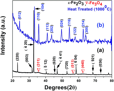 |
| | Fig. 1 Merged X-ray diffraction patterns of the (a) composite showing the formation of ε-Fe2O3 and Fe3O4 phases; (b) the transformation to hematite upon heat treatment at 1000 °C. | |
Peak broadening is an effect which depends both on the size and the strain, as the size decreases crystal imperfections increase; the imperfection may be lattice defects within the crystal or at the surface due to broken symmetry. The strain is given by the equation
| |
 | (3) |
Assuming the size and strain contributions to be independent of each other, eqn (1) and (3) can be combined to give the expression21
| |
 | (4) |
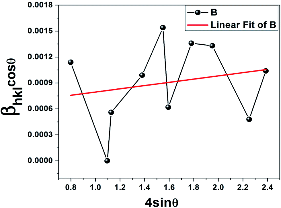
Based on the W–H equation, the W–H plot (βhklcosθ vs. 4sinθ) was drawn for only the ε-Fe2O3 peaks, which assesses the microstrain in the composite as well as the crystallite size (Fig. 2). Lattice strain is a measure of the distribution of lattice constants arising from crystal imperfections mainly lattice dislocations.22 The crystallite size (≈228 nm) was estimated from the y-intercept of the linear fit (kλ/D = 0.000608) whereas the strain was calculated from the slope (ε = βhklcosθ/4sinθ = 0.000187). The positive strain might be due to the lattice shrinkage of the ε phase along the c axis as a result of growth on the graphene substrate, such an effect has been previously reported for Fe doped ZnO nanoparticles.23 Previous work on thin film deposition of evaporated metal and organic insulator on graphene substrate has also reported strain induced shrinkage after heat treatment.24 In addition, doping of metal ions within the crystal lattice can also generate strain as observed in our case. The scattered points corresponding to each crystallographic plane in the W–H plot can be attributed to the anisotropy of the dislocation strain field in the elastic medium, as well as to the contribution of planar defects.25 It must be borne in mind that eqn (4) represents the uniform deformation model (UDM) where the strain is assumed to be uniform in all crystallographic directions for an isotropic material; in our case since the nanoparticles have grown on graphene substrate with size restriction along the surface plane, the strain is non-uniform.22,23 The X-ray reflections seem to increase the constructive interference of diffracted beams from thousands of ultrasmall particles on the graphene substrate. It seems that the iron ions (Fe2+) which encountered graphene surface were subsequently oxidized to the ε-Fe2O3 phase; the remaining ions in the solution formed Fe3O4. The intensity of the 100% peak of ε-Fe2O3 suggests that graphene has managed to attract maximum ferrous ions. The hydrodynamic radius (RH) and zeta potential estimated from the dynamic light scattering (DLS) experiments proved graphene–IONP interaction (Table 1). A comparison with IONPs without graphene shows that the stability has gone up and the polydispersity index (PdI) decreased in the presence of graphene, proving uniformity.
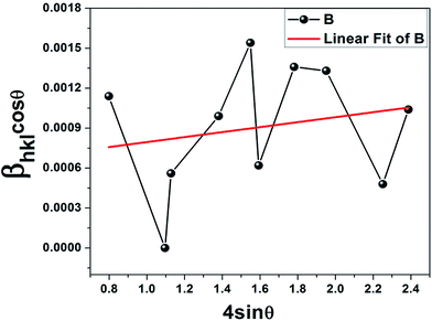 |
| | Fig. 2 Williamson–Hall plot showing positive strain in the epsilon phase; the average crystallite size was equal to 250 nm. | |
Table 1 DLS data at various experimental stages of G–IONP formation
| Sample |
Hydrodynamic radius (nm) |
Zeta potential (mV) |
PdI |
| Protein–polymer mixture |
95.8 |
+18.2 |
0.427 |
| Protein–polymer + graphite |
127.6 |
+15.3 |
0.419 |
| G–IONP |
34.0 |
−22.8 |
0.309 |
| IONP |
29.3 |
−15.2 |
0.384 |
2.2 Transmission electron microscopy
The TEM micrographs of the G–IONP composites imaged at different magnifications clearly show graphene flakes of less than 250 nm in length and 60–70 nm in breadth (Fig. 3A(a)). Functionalizing a free standing graphene is definitely easier than that on a substrate; this is where the multi-functionality of the proteins and polymers used in exfoliation plays a role. As compared to existing reports where nitrogen doped graphene–γ-Fe2O3 conjugates exhibit curling;26 this 4–5 layer functionalized graphene provides just the right strain to prevent excessive buckling of the graphene sheets in the presence of iron ions. The distribution of the nanoparticles on each graphene sheet is uniform and shows tendencies of alignment (Fig. 3A(b) and (c)). The histogram in (Fig. 3B) corresponding to the image shows the graphene surface densely coated with narrowly distributed aligned ε-Fe2O3 nanocrystals with average size of 1 nm. The size distribution of 100 particles was fitted with the log-normal function using Origin 8 software given by
where y0 is the offset (=0.07), A is the amplitude (=0.13968), w is the width (=0.06) and xC is the peak position (or the mean size) centred at x = 1 nm; the peak width is given by
where N is the sampling number, xi is the random variable and ![[x with combining macron]](https://www.rsc.org/images/entities/i_char_0078_0304.gif) is the mean size. Surprisingly, the crystallite size in XRD was much bigger than this size and the strain was positive. The increase in the crystallite size (≈250 nm) as evident from the sharp peaks was thus thought to be due to the formation of self assembled clusters triggered by magnetic dipolar interactions. The indexed SAD pattern (Fig. 3A(d)) proves the formation of ε-Fe2O3; the polycrystalline rings are merged with bright spots; the aperture size being large, a large number of particles may have been focused at a time. The rings were indexed as (220), (240), (
is the mean size. Surprisingly, the crystallite size in XRD was much bigger than this size and the strain was positive. The increase in the crystallite size (≈250 nm) as evident from the sharp peaks was thus thought to be due to the formation of self assembled clusters triggered by magnetic dipolar interactions. The indexed SAD pattern (Fig. 3A(d)) proves the formation of ε-Fe2O3; the polycrystalline rings are merged with bright spots; the aperture size being large, a large number of particles may have been focused at a time. The rings were indexed as (220), (240), (![[4 with combining macron]](https://www.rsc.org/images/entities/char_0034_0304.gif) 41) and (272) crystal planes of monoclinic ε-Fe2O3 (JCPDS PDF No.: 16-0653). Interestingly, the indexed (220) plane of ε-Fe2O3 belongs to the same family of planes (110) of graphite; there seems to be a close structural similarity between the monoclinic phase of iron oxide and the hexagonal lattice of graphene. Another startling observation regarding plane growth is that the XRD pattern exhibits a series of peaks belonging to the same family of planes namely (220), (20), (620) and (720) respectively; there seems to be a preferential orientation along the [220] plane direction. We thus conclude from TEM data that the particle size of the epsilon phase was so small (≈1 nm) that it was impossible for the X-rays to measure the coherent length; instead it measured bigger graphene sheets coated with the particles.
41) and (272) crystal planes of monoclinic ε-Fe2O3 (JCPDS PDF No.: 16-0653). Interestingly, the indexed (220) plane of ε-Fe2O3 belongs to the same family of planes (110) of graphite; there seems to be a close structural similarity between the monoclinic phase of iron oxide and the hexagonal lattice of graphene. Another startling observation regarding plane growth is that the XRD pattern exhibits a series of peaks belonging to the same family of planes namely (220), (20), (620) and (720) respectively; there seems to be a preferential orientation along the [220] plane direction. We thus conclude from TEM data that the particle size of the epsilon phase was so small (≈1 nm) that it was impossible for the X-rays to measure the coherent length; instead it measured bigger graphene sheets coated with the particles.
 |
| | Fig. 3 A (a–c) TEM micrographs showing G–IONP composites: (a) global picture of the composite flakes; (b) alignment of IONP particles on the flakes; (c) micro alignment of an enlarged flake (d) the indexed SAD pattern of (c) showing polycrystalline rings of the ε-Fe2O3 phase. (B) Particle size distribution plot of uniformly distributed epsilon phase on graphene substrate with a mean particle size of 1 nm. | |
2.3 Raman spectroscopy
The Raman spectrum (intensity corrected with respect to the control spectrum of the protein–polymer mixture) reflects a true composite (Fig. 4). Proteins contain several Raman active amide bonds; the amide I band comprising of C![[double bond, length as m-dash]](https://www.rsc.org/images/entities/char_e001.gif) O stretch appears at ∼1650 cm−1, the amide II band comprising of N–H bend and C–N stretch occurs at ∼1550 cm−1 while the amide III band comprising of C–N stretch and N–H bend appears at ∼1300 cm−1;27 the peaks at 1590, 1407 and 1332 cm−1 correspond to these characteristic signatures in the composite which overlap with the G and D bands of graphene. The 2D band is the second order overtone of the D band, and is formed due to the result of a two phonon lattice vibrational process, but unlike the D band, it does not need to be activated by proximity to a defect.28 As a result the 2D band is always a strong band in graphene even when there is no D band present; in pristine graphene this band is also used to determine graphene layer thickness.28 In contrast to the G band position method, the 2D band method depends not only on band position but also on band shape. Here, the 2D band at (≈2687 cm−1) was masked by the more intense protein–polymer peaks. The peaks at 2444, 3056, 3132 and 3469 cm−1 are due to S–H(sulfhydryl), C–H, =C–H and N–H stretching in proteins; the last mode also corresponds to OH stretching vibration of PVA. The peaks at 694, 488 and 426 cm−1 are the characteristic Fe–O bond vibrations of iron oxide.9 The blue shift of the G band which normally occurs at 1580 cm−1 can be attributed to the in plane isotropic compressive strain due to the nucleation and growth of nanoparticles on the graphene substrate. Such strain induced growth has been reported for thin film deposited graphene which is quite similar to our case where the graphene acts as the substrate and iron oxide as the film.24 The presence of the D band proves that defects have been introduced in graphene due to iron oxide nucleation.
O stretch appears at ∼1650 cm−1, the amide II band comprising of N–H bend and C–N stretch occurs at ∼1550 cm−1 while the amide III band comprising of C–N stretch and N–H bend appears at ∼1300 cm−1;27 the peaks at 1590, 1407 and 1332 cm−1 correspond to these characteristic signatures in the composite which overlap with the G and D bands of graphene. The 2D band is the second order overtone of the D band, and is formed due to the result of a two phonon lattice vibrational process, but unlike the D band, it does not need to be activated by proximity to a defect.28 As a result the 2D band is always a strong band in graphene even when there is no D band present; in pristine graphene this band is also used to determine graphene layer thickness.28 In contrast to the G band position method, the 2D band method depends not only on band position but also on band shape. Here, the 2D band at (≈2687 cm−1) was masked by the more intense protein–polymer peaks. The peaks at 2444, 3056, 3132 and 3469 cm−1 are due to S–H(sulfhydryl), C–H, =C–H and N–H stretching in proteins; the last mode also corresponds to OH stretching vibration of PVA. The peaks at 694, 488 and 426 cm−1 are the characteristic Fe–O bond vibrations of iron oxide.9 The blue shift of the G band which normally occurs at 1580 cm−1 can be attributed to the in plane isotropic compressive strain due to the nucleation and growth of nanoparticles on the graphene substrate. Such strain induced growth has been reported for thin film deposited graphene which is quite similar to our case where the graphene acts as the substrate and iron oxide as the film.24 The presence of the D band proves that defects have been introduced in graphene due to iron oxide nucleation.
 |
| | Fig. 4 Raman spectra of the G–IONP composite. | |
2.4 X-ray photoelectron spectroscopy
XPS is a surface sensitive technique where the ionic state of elements in compounds can be determined accurately from their binding energies (B.E.). The full spectrum was recorded in the range 1100–0 eV which confirmed the presence of carbon, nitrogen, oxygen and iron; slow scans were also done specifically at the following regions: B.E. ∼285 eV for C1s, ∼395 eV for N1s, ∼530 eV for O1s and ∼710 eV for Fe2p core level peaks (Fig. 5). As the protein–polymer mixture is used for both exfoliating graphite and templating iron oxide it is expected to get protein signatures in the spectra. The C1s peak was fitted with 5 components corresponding to C–O/C–N amide (285.2 eV), H–CO peptide (287 eV) and O–CO carboxylic (289 eV) bonds;29,30 the lower B.E. peaks (280.9 eV & 283.4 eV) arise due to the interaction of electropositive iron (Fe3+/Fe2+) ions with the carbon lattice of graphene. The N1s peak was deconvoluted using 5 components; the peaks at 401.8 eV, 400.3 eV & 398.8 eV correspond to the protonated amino groups (NH4+) and amide O–(CNH) bonds present in proteins; the peaks at lower binding energies correspond to the deprotonated amine groups NH2− (395.3 eV) and Fe–N (392.4 eV) bonds.31–34 The O1s spectra consisted of 3 multiplets corresponding to the Fe–O (528.5 eV), O–C/O–H (530.3 eV) and OC (531.8 eV) bonds.29 The iron region consisted of two peaks corresponding to the 2p3/2 (≈711 eV) and 2p1/2 (≈724.75 eV) transitions; the 2p3/2 peak was further deconvoluted into two components, the primary being 711 eV corresponding to the high spin Fe3+ of Fe2O3. Pure Fe2O3 exists in a wide variety of polymorphic forms; every polymorph consists of Fe–O linkages that are arranged in octahedral and tetrahedral lattices pertaining to the different co-ordination of O2− and Fe3+ ions within the crystal. Keeping this in mind and also the fact that alpha and gamma are the most stable phases, the confirmation of ε-Fe2O3 was done from XRD and TEM results. The secondary component at 713.8 eV corresponds to the high spin Fe3+ state of Fe3O4; a consistent shift towards higher binding energy (+0.3 eV) was observed from reported standard values of pure α and γ polymorphs and magnetite.35 Such an effect can be attributed to the effective functionalization of Fe atoms with the graphene surface and also with the template. A charge transfer satellite peak at 719.1 eV was also observed which indicates Fe2O3 formation since such a peak is absent in magnetite; the results suggest that the composites contain both the phases.35
 |
| | Fig. 5 XPS Spectra of the composite showing the spectral multiplets of (a) C1s, (b) N1s, (c) O1s and (d) Fe2p core level peaks. | |
2.5 Magnetic measurements
Pure graphene is diamagnetic in nature, however shows weak ferromagnetic ordering due to incorporation of defects induced by wrinkles, breakage or functionalization.36 As the synthesized graphene–iron oxide composites consist of both diamagnetic and ferrimagnetic components, the magnetic saturation (MS) is expected to decrease. The room temperature (300 K) hysteresis showed the typical “S” shaped behavior of superparamagnetic particles with magnetization (M) equal to 6.21 emu g−1 and negligible coercivity, HC ≈ 20.5 Oe (Fig. 6); magnetization was much lower than that of undoped ε-Fe2O3 (≈15 emu g−1),15 the moments did not saturate even at a field of 5 T. The low values of magnetization could be attributed to the ultrasmall size of the particles and surface pinning of magnetic moments in graphene.37,38
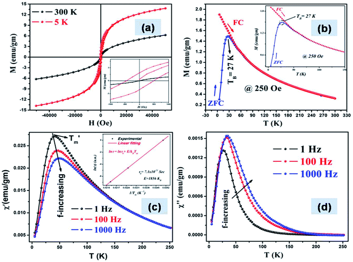 |
| | Fig. 6 (a) M–H curves of the composites measured at 300 K and 5 K (b) the M–T curves shows blocking below 27 K and absence of dipolar interactions; (c) real and (d) imaginary part of the susceptibility as a function of temperature measured at three different frequencies; (c) inset the Néel–Arrhenius plot showing superparamagnetic relaxation. | |
 |
| | Fig. 7 Field cooled (FC) and zero field cooled (ZFC) hysteresis taken at 5 K and 3 Tesla magnetic field showing exchange bias effect. | |
The presence of coercivity, however small, may be attributed to the small size and surface anisotropy. The particles when cooled to 5 K resulted in an increase of M (≈13.74) emu g−1 and HC (≈466.3 Oe) (see Table 2). The decrease in coercivity at room temperature can also be attributed to the substitution of Fe3+ with excess Fe2+ ions in the ε-Fe2O3 lattice. Previous reports on Gallium doped ε-Fe2O3 nanoparticles (ε-GaxFe2−xO3) have shown that with an increase in Ga3+ substitution, the room temperature coercivity decreases.39 Similar substitution driven effects have also been observed for aluminum doped ε-Fe2O3 (ε-AlxFe2−xO3). The cationic radii of atoms can either be smaller than Fe3+ which results in compression of the lattice constants,40 or bigger radii like In3+, then the lattice is enlarged.41 The positive lattice strain observed in W–H plot results from the bigger Fe2+ ions in the high spin state (as confirmed from XPS) for both octahedral as well as tetrahedral co-ordination compared to the high spin Fe3+, which results in the formation of the highly asymmetric strained monoclinic phase. On comparison, previous report on multifunctional graphene nanosheets coated with high density Fe3O4 nanoparticles of 1.2 nm diameter exhibited even lower saturated magnetization of 0.5 emu g−1.5 The temperature dependent magnetization (M–T) was measured to estimate the blocking temperature (TB) (Fig. 6b); the sharp maxima of the ZFC curves correspond to TB which separates the superparamagnetic regime from the blocked state. The sharpness of the ZFC profile can be attributed to a very narrow size distribution of monodispersed particles with negligible dipolar interactions (Fig. 3B). This was startling and the only explanation that we could arrive at was literal coating of graphene flakes with 1 nm sized iron oxide particles. Another interesting observation was that the magnetization during FC cycle kept on increasing below the TB which again proved the absence of any type of magnetic interaction among the particles, collective behavior usually forms a plateau.42 The magnetic anisotropy constant has been calculated from the M–T curve from the relation
where
Keff is the effective magnetic anisotropy constant,
V is the particle volume,
KB is the Boltzmann constant (1.3807 × 10
−16 erg K
−1) and
TB is the blocking temperature. Though the presence of graphene did not affect the Neel relaxation; the anisotropy increased after graphene functionalization (see
Table 2). For particle sizes below 10 nm, the broken translational symmetry of the crystal and lower coordination at the surface leads to a stronger anisotropy than in the bulk;
43 in our case the size was ≈10 times smaller than this limit.
Table 2 Magnetic parameters of the graphene–iron oxide nanocomposites
| Sample |
Particle Size (nm) |
Temp. (Kelvin) |
MSa (emu g−1) |
MRb (emu g−1) |
HCc (Oe) |
Keffd (×105 erg cm−3) |
TBe (Kelvin) |
| MS = saturation magnetization. MR = retentivity. HC = coercivity. Keff = effective anisotropy constant (Keff). TB = blocking temperature. |
| G–IONP |
1 |
300 |
6.21 |
0.021 |
20.50 |
2900.41 |
27 |
| 5 |
13.74 |
1.960 |
466.35 |
— |
— |
The frequency dependence of the magnetic relaxation was investigated by measuring the susceptibility (χ) with temperature (within the range 5–267 K) in the presence of an external ac magnetic field. The field was applied at three different oscillating frequencies viz. 1 Hz, 100 Hz and 1000 Hz and the dynamical behavior was studied by frequency modulation. In the presence of a time-varying field given by H(t) = H0e−iωt, χ can be expressed as the sum of an in-phase component or the real part (χ′) and an out-of-phase component or the imaginary part (χ′′); mathematically it is expressed as
It should be noted that if the frequency (ω) of the external field is very fast as compared with the relaxation time (τ) of the particles i.e. ω ≫ τ−1, then the particles are unable to oscillate and magnetization decreases to zero, maximum at the resonance condition ω = τ−1 and when (ω ≪ τ −1), the magnetization is always in equilibrium over the time-scale of the measurement.44 For an assembly of magnetic nanoparticles, mutual interaction can be determined from the nature of the Neel–Arrhenius plot (lnτ vs. 1/Tmax); for superparamagnetic systems, the plot follows a linear relationship given by the equation
| |
 | (7) |
From Fig. 6c we can see that the Tmax gradually shifts towards higher values with increasing frequency from 41.1 K (for 1 Hz) to 47.2 K (for 100 Hz) and finally 50.12 K (for 1000 Hz); χ′ on the other hand follows the reverse trend decreasing from 0.0271 emu g−1 (for 1 Hz) to 0.0239 emu g−1 (for 100 Hz) to 0.0222 emu g−1 (for 1000 Hz); these results can be attributed to superparamagnetic nature of the samples.45,46 The relaxation time was calculated from the experimental values and the Neel–Arrhenius plot was drawn and fitted; the linear regression value was 0.99; all the data points matched well with eqn (7).
To investigate the presence of exchange bias (EB) in the material, hysteresis loops were taken at 5 K temperature in ZFC and FC conditions in 3 Tesla field. Field cooled (FC) and zero field cooled (ZFC) magnetic measurements show negligible dipolar interactions (see Fig. 6b) i.e., the particles behave as non interacting superparamagnets; magnetic studies, however support the TEM results. EB is an interfacial magnetic phenomena associated with the exchange anisotropy created at the interfaces between different magnetic phases.47,48 It requires the presence of magnetic interfaces in intimate contact and is not dependant on dipolar interactions between the phases.49 Though, exchange bias is typically seen for composites and thin films, the interface coupling can occur in systems having ferro–antiferromagnetic, ferro–ferrimagnetic as well as ferri–antiferromagnetic hybrid structures; a ferrimagnetic core with a frustrated shell in ultrasmall particles can also show EB.48–50 There are reports that low temperature antiferromagnetic ordering is possible for graphene embedded in hexagonal boron nitride as well as for strained graphene; the estimated Neel temperature was ≈100 K for the former case.51,52 Since our template contains proteins containing nitrogen functional groups, the binding with the delocalized π electrons alter their electronic states which favors antiferromagnetic coupling at low temperature; effectively creating antiferro–ferrimagnetic hybrid structures. The composite was cooled to 5 K in ZFC condition and hysteresis recorded which was repeated in a field of 3 Tesla in FC condition; loop shift of the hysteresis curve towards the negative field axis was observed; an EB of 118 Oe was measured for the G–IONP composites, while no appreciable shift was observed for the pristine iron oxide (Fig. S4†).
3. Experimental
3.1 Materials
Precursor natural graphite powder (Product No. 14734, 200 mesh size ∼75 μm) was bought from Alfa Aesar. Type-I collagen (CL) from bovine achilles tendon and bovine serum albumin (BSA) was obtained from Sigma-Aldrich; poly(vinyl) alcohol (PVA, av. mol wt = 95000, 95% hydrolyzed) from Acros Organics, hydrated iron(II) chloride and anhydrous iron(III) chloride from Loba Chemie and Rankem respectively; liquor ammonia (30% v/v) and citric acid monohydrate from Rankem.
3.2 Synthesis
IONPs were synthesized in PBS buffer using a combination of a sheet like protein (CL), a globular protein (BSA) and a biocompatible polymer (PVA) in fixed ratio (0.01% CL, 0.01% PVA and 0.001% BSA); the biomolecules interact amongst themselves to form a reproducible biomimetic template in aqueous environment, the template acts as micro reactors within which the particles nucleate and grow.38 0.01% graphite was dispersed in this template and stirred for 6 h followed by incubation for 7 days, the black exfoliated graphene dispersion was subjected to mild sonication (150 Watts, 40 KHz) thrice for 10 min at an interval of 5 min 2 M:1 M (Fe3+:Fe2+) stock solution was added to the graphene dispersion and incubated overnight (∼16 h) with stirring at 200 rpm. Liquor ammonia was then added dropwise; post oxidation, the colour changed from yellowish brown to blackish-brown which indicated the formation of iron oxide nanocrystals. The temperature was subsequently increased to 60 °C and freshly prepared citric acid was added to get a stable dispersion. The heating was stopped and the G–IONP colloidal fluid was removed and centrifuged at 8000 rpm for 30 min in REMI PR-24 machine. The supernatant was collected and dialyzed against double distilled water which was changed after every 2 h using HIMEDIA cellulose membrane. The dialyzed fluid was vacuum dried at 60 °C for 24 h and crushed in an agate; the composite powder was used for characterization. The experiments repeated thrice to confirm the findings.
3.3 Characterization
Phase purity and structural studies were done using Bruker D8 Discover diffractometer, operated at 40 kV with CuKα radiation (λ = 1.5418 Å) in the 2θ range 20–80°, step size equal to 0.02° per step and scan speed equal to 5 s per step. High resolution TEM and selected area diffraction (SAD) were performed in JEOL JEM-2100 microscope operated at 200 kV equipped with a GATAN CCD camera with a point to point resolution of 0.194 nm and lattice resolution of 0.14 nm. The composite powder was dispersed in water, sonicated and dried on copper grids (∼300 mesh). DH, zeta potential and polydispersity index (PdI) were measured in Zetasizer Nano ZS, Malvern Instruments, using the back scattering technique at an angle of 173°. FTIR were recorded by the KBr pellet method in Nicolet 5700 spectrometer. TG/DTA was performed in the analyzer SDTQ 600 TA Instruments. Raman spectroscopy was done in AlmegaXR, Thermo Scientific dispersive Raman spectrometer (using a Nd:YAG laser source, λ = 532 nm) by drying a drop of the composite dispersion on polished copper substrates for surface enhanced signals. XPS spectra were recorded using a SPECS spectrometer with MgKα source (1253.6 eV). Few drops of the dispersion were dried on glass substrates and then inserted into a vacuum chamber having a pressure ≈109 Torr. The conditions used for all the survey scans were as follows: energy range = 1100–0 eV, pass energy = 25 eV, step size = 0.1 eV. Spectra were de-convoluted using Casa XPS software, post Shirley background subtraction. All the peaks were calibrated with respect to the standard C1s binding energy peak of pure graphite at 284.5 eV. Magnetic measurements were done in SQUID magnetometer (MPMS XL7, Quantum Design, USA); all the measurements were taken in heating cycle (heating rate = 2 K min−1). Defects studies were carried out by positron annihilation lifetime measurements using a fast–fast coincidence system consisting of two 1 inch tapered off BaF2 scintillators coupled to XP 2020Q photo multiplier tubes. The lifetime data was analyzed by the PATFIT programme after the necessary source correction due to thin Ni foils.53
4. Conclusions
The present study describes a biomimetic route to synthesize stable ε-Fe2O3 using ferrous/ferric: graphene ratio 850:1 at ambient conditions. Based on previous reports that iron oxides intercalate layered compounds, we set out to make G–IONP composites for improved biomedical applications. This resulted in iron oxide nanoparticles of the average size of 1 nm, this by itself exhibits unique features that strongly differ from their bulk components. In addition, the fact that it is embedded in 3–4 layer graphene changes the phase from cubic to monoclinic. The cover density of the aligned IONPs on the graphene flakes as seen from TEM is literally like a coating, supported by the bigger crystallite size of XRD and magnetic force microscopy results (graphical abstract). This is perhaps the easiest route to bulk synthesis of this phase reported so far.
Acknowledgements
The authors would like to acknowledge the contribution of Drs SR Singh, Arvind Sinha, A K Pramanick, Sandip Ghosh Chowdhury, Jay Chakraborty and Mainak Ghosh for TEM and XRD analysis. The authors would like to thank Ms Pallawi Gupta and Ms Divya Kumari for the experimental work. One of the authors (SB) would like to acknowledge the Council of Scientific and Industrial Research (CSIR), India for granting Senior Research Fellowship (No.: 31/10(0047)/2012.EMR-I).
Notes and references
- S. Bhattacharya, S. Mishra, P. Gupta, P. Tiwari, M. Ghosh, A. K. Pramanick, D. P. Mishra and S. Nayar, RSC Adv., 2015, 5, 44447–44457 CAS.
- S. C. Hernandez, F. J. Bezares, J. T. Robinson, J. D. Caldwell and S. G. Walton, Carbon, 2013, 60, 84–93 CrossRef CAS PubMed.
- M. Sepioni, R. R. Nair, S. Rablen, J. Narayanan, F. Tuna, R. Winpenny, A. K. Geim and I. V. Grigorieva, Phys. Rev. Lett., 2010, 105, 207205 CrossRef CAS.
- S. Bhattacharya, L. Sheikh, V. Tiwari, M. Ghosh, J. N. Patel, A. B. Patel and S. Nayar, J. Biomed. Nanotechnol., 2014, 10, 811–819 CrossRef CAS PubMed.
- H. He and C. Gao, ACS Appl. Mater. Interfaces, 2010, 2, 3201–3210 CAS.
- P. Laaksonen, M. Kainlauri, T. Laaksonen, A. Shchepetov, J. Jiang, J. Ahopelto and M. B. Linder, Angew. Chem., Int. Ed., 2010, 49, 4946–4949 CrossRef CAS PubMed.
- J. Jin, S. Okhoshi and K. Hashimoto, Adv. Mater., 2004, 16, 48–51 CrossRef CAS PubMed.
- C. Domingo, R. Rodriguez-Clemente and M. Blesa, J. Colloid Interface Sci., 1994, 165, 244–252 CrossRef CAS.
- R. M. Cornell and U. Schwertmann, in The Iron Oxides: Structure, Properties, Reactions, Occurrences and Uses, ed. R. M. Cornell and U. Schwertmann, Wiley-VCH Verlag GmbH & Co, Weinheim, 2nd edn, 2003 Search PubMed.
- H. Forestier and G. Guiot-Guillain, C. R. Acad. Sci., 1934, 199, 720 CAS.
- E. Tronc, C. Chaneac and J. P. Jolivet, J. Solid State Chem., 1998, 139, 93–104 CrossRef CAS.
- K. Kelm and W. Mader, Z. Anorg. Allg. Chem., 2005, 631, 2383–2389 CrossRef CAS PubMed.
- R. Zboril, M. Mashlan, M. Barcova and M. Vujtek, Hyperfine Interact., 2002, 139, 597–606 CrossRef.
- M. Popovici, M. Gich, D. Niznansky, A. Roig, S. Cecilia, L. Casas, E. Molins, K. Zaveta, C. Enache, J. Sort, S. Brion, G. Chouteau and J. Nogues, Chem. Mater., 2004, 16, 5542–5548 CrossRef CAS.
- J. Tucek, R. Zboril, A. Namai and S. Ohkoshi, Chem. Mater., 2010, 22, 6483–6505 CrossRef CAS.
- E. Taboada, M. Gich and A. Roig, ACS Nano, 2009, 3, 3377–3382 CrossRef CAS PubMed.
- P. Brázda, D. Niznansky, J. Rehspringer and J. P. Vejpravova, J. Sol-Gel Sci. Technol., 2009, 51, 78–83 CrossRef.
- L. Machala, J. Tuček and R. Zbořil, Chem. Mater., 2011, 23, 3255–3272 CrossRef CAS.
- R. G. Mc Lean, M. A. Schofield, W. F. Kean, C. V. Sommer, D. P. Robertson, D. Toth and M. Gajdarziska-Josifovska, Eur. J. Mineral., 2001, 13, 1235–1242 CrossRef PubMed.
- R. Schrader and G. Z. Buttner, Z. Anorg. Allg. Chem., 1963, 320, 220–234 CrossRef CAS PubMed.
- L. K. Brar, G. Singla and O. P. Pandey, RSC Adv., 2015, 5, 1406–1416 RSC.
- V. D. Mote, Y. Purushotham and B. N. Dole, Journal of Theoretical and Applied Physics, 2012, 6, 1–8 CrossRef.
- Y. T. Prabhu, K. V. Rao, V. S. S. Kumar and B. S. Kumari, Int. J. Eng. Adv. Tech., 2013, 2, 268–274 Search PubMed.
- H. Shioya, M. F. Craciun, S. Russo, M. Yamamoto and S. Tarucha, Nano Lett., 2014, 14, 1158–1163 CrossRef CAS PubMed.
- P. Scardi, M. Leonia and R. Delhez, J. Appl. Crystallogr., 2004, 37, 381–390 CrossRef CAS.
- T. Sharifi, E. Gracia-Espino, H. R. Barzegar, X. Jia, F. Nitze, G. P. Nordblad, C. W. Tai and T. Wågberg, Nat. Commun., 2013, 4, 23191–23199 Search PubMed.
- http://www.horiba.com/fileadmin/uploads/Scientific/Documents/Raman/HORIBA_webinar_proteins.pdf.
- A. C. Ferrari, Solid State Commun., 2007, 143, 47–57 CrossRef CAS PubMed.
- P. Thanikaivelan, N. T. Narayanan, B. K. Pradhan and P. M. Ajayan, Sci. Rep., 2012, 2(230), 1–7 Search PubMed.
- J. Guo, R. Wang, W. W. Tjiu, J. Pan and T. Liu, J. Hazard. Mater., 2012, 225, 63–73 CrossRef PubMed.
- S. Barazzouk and C. Daneault, Nanomaterials, 2012, 2, 187–205 CrossRef CAS PubMed.
- M. Blum, PhD Thesis, University of Wurzburg, 2009.
- K. Kamiya, K. Hashimoto and S. Nakanishi, Chem. Commun., 2012, 48, 10213–10215 RSC.
- W. T. Zheng, K. Z. Xing, N. Hellgren, M. Logdlund, A. Johansson, U. Gelivs, W. R. Salaneck and J. E. Sundgren, J. Electron Spectrosc. Relat. Phenom., 1997, 87, 45–49 CrossRef CAS.
- A. P. Grosvenor, B. A. Kobe, M. C. Beisinger and N. S. McIntyre, Surf. Interface Anal., 2004, 36, 1564–1574 CrossRef CAS PubMed.
- L. Chen, L. Guo, Z. Li, H. Zhang, J. Lin, J. Huang, S. Jin and X. Chen, Sci. Rep., 2013, 3(2599), 1–6 Search PubMed.
- W. Baaziz, B. P. Pichon, S. Fleutot, Y. Liu, C. Lefevre, J. M. Greneche, M. Toumi, T. Mhiri and S. B. Colin, J. Phys. Chem. C, 2014, 118, 3795–3810 CAS.
- S. Bhattacharya, A. Roychowdhury, V. Tiwari, A. Prasad, R. S. Ningthoujam, A. B. Patel, D. Das and S. Nayar, RSC Adv., 2015, 5, 13777–13786 RSC.
- S. Ohkoshi, S. Kuroki, S. Sakurai, K. Matsumoto, K. Sato and S. A. Sasaki, Angew. Chem., 2007, 119, 8544–8547 CrossRef PubMed.
- A. Namai, S. Sakurai, M. Nakajima, T. Suemoto, K. Matsumoto, M. Goto, S. Sasaki and S. Ohkoshi, J. Am. Chem. Soc., 2009, 131, 1170–1173 CrossRef CAS PubMed.
- S. Sakurai, S. Kuroki, H. Tokoro, K. Hashimoto and S. Ohkoshi, Adv. Funct. Mater., 2007, 17, 2278–2282 CrossRef CAS PubMed.
- D. Fiorani and D. Peddis, J. Phys.: Conf. Ser., 2014, 521(012006), 1–9 Search PubMed.
- A. Cabot, A. P. Alivisatos, V. F. Puntes, L. Balcells, O. Iglesias and A. Labarta, Phys. Rev. B: Condens. Matter Mater. Phys., 2009, 79, 094419–094425 CrossRef.
- E. Tronc, D. Fiorani, M. Nogues, A. M. Testa, F. Lucari, F. D'Orazio, J. M. Greneche, W. Wernsdorfer, N. Galvezg, C. Chaneaca, D. Mailly and J. P. Jolivet, J. Magn. Magn. Mater., 2003, 262, 6–14 CrossRef CAS.
- A. Roychowdhury, S. P. Pati, S. Kumar and D. Das, Mater. Chem. Phys., 2015, 151, 105–111 CrossRef CAS PubMed.
- A. Roychowdhury, S. P. Pati, S. Kumar and D. Das, Powder Technol., 2014, 254, 583–590 CrossRef CAS PubMed.
- R. L. Stamps, J. Phys. D: Appl. Phys., 2000, 33, R247–R268 CrossRef CAS.
- J. Nogues and I. K. Schuller, J. Magn. Magn. Mater., 1999, 192, 203–232 CrossRef CAS.
- H. M. Nguyen, C. H. Lee, P. Y. Hsiao and M. H. Phan, J. Appl. Phys., 2011, 110, 043909–043915 CrossRef PubMed.
- O. Iglesias, A. Labarta and X. Batlle, J. Nanosci. Nanotechnol., 2008, 8, 2761–2780 CAS.
- A. Ramasubramaniam and D. Naveh, Phys. Rev. B: Condens. Matter Mater. Phys., 2011, 84, 075405–075410 CrossRef.
- B. Roy, F. F. Assaad and I. F. Herbut, Phys. Rev. X, 2014, 4, 021042 Search PubMed.
- P. Kirkegaard and M. Eldrup, Comput. Phys. Commun., 1972, 3, 240–255 CrossRef.
Footnote |
| † Electronic supplementary information (ESI) available. See DOI: 10.1039/c5ra17247k |
|
| This journal is © The Royal Society of Chemistry 2015 |
Click here to see how this site uses Cookies. View our privacy policy here.