
Fully screen printed highly conductive electrodes on various flexible substrates for asymmetric supercapacitors†
Siliang Wanga,
Nishuang Liu*a,
Congxing Yanga,
Weijie Liua,
Jun Sua,
Luying Lia,
Changping Yangb and
Yihua Gao*ab
aCenter for Nanoscale Characterization & Devices (CNCD), Wuhan National Laboratory for Optoelectronics (WNLO) & School of Physics, Huazhong University of Science and Technology (HUST), LuoyuRoad 1037, Wuhan 430074, China. E-mail: gaoyihua@hust.edu.cn; nishuang_liu@foxmail.com
bHubei Collaborative Innovation Center for Advanced Organic Chemical Materials, Hubei University, 368 Youyi Avenue, Wuhan 430062, China
First published on 25th September 2015
Abstract
Highly flexible conductive electrodes were prepared by screen printing a commercial carbon nanoparticle ink onto various substrates such as clothes, polyethylene terephthalate (PET) and paper. The flexible electrodes showed good stability during the bending test and could act as a foldable electric circuit. Multi-walled carbon nanotubes–manganese dioxide (MWCNTs–MnO2) anodes and multi-walled carbon nanotubes–molybdenum trioxide (MWCNTs–MoO3) cathodes for asymmetric supercapacitors (ASCs) were screen printed onto carbon nanoparticle electrodes, which acted as a collector. The fully screen printed supercapacitor has a wide operating potential window of 1.7 V and exhibits excellent electrochemical performance, e.g. a high energy density of 11.04 mW h cm−3 at a power density of 614.6 mW cm−3, a high retention ratio of ∼91.3% of its initial capacitance after 5000 cycles. The screen-printing acting as a simple, versatile, fast, and cost-effective printing method can be fully integrated with the fabrication process in current printed electronics and has potential applications for energy storage.
Introduction
Flexible displays,1,2 flexible and conformal antenna arrays,3,4 electric circuits and chemical sensors,5 electronic solar cell arrays,6 radio frequency identification tags,7 and microstructure electrochemical capacitors8–10 as flexible optoelectronic and electronic devices have gained rapid developments and promoted the demands for high-performance flexible conductive electrodes.Many methods can be used to produce flexible conductive electrodes such as sputtering,11,12 chemical vapor deposition13 and filtration.14 These methods are widely thought to be a high-cost process, because they require large scale equipment with a vacuum system and complicated steps in the process. Screen printing is one of the simplest, most versatile, fast, and cost-effective printing techniques to make flexible conductive electrodes. It does not require expensive vacuum technology and can be applied to any surface shape and size such as glass, plastics, or clothes. Future developments are aiming at light, thin, cheap, flexible, and sustainable solutions, with wearable electronics as one typical application. More specifically, “printed electronics”,15 including printable transistors,16 solar cells17 and organic light emitting diodes,18 as emerging field has the potential to meet these goals in future applications. However, for these applications a compatible energy source is still lacking. Fully screen printed energy storage devices show great promise for allowing full integration into the manufacturing process of printed electronics.
In flexible and foldable conductors, conducting polymers,19,20 graphene,21,22 as well as metal nanostructures23–27 have become dominant research topics. However, conducting polymers and graphene have very limited performance and applications due to the instability, relatively low electrical conductivity or expensive material cost. Metal nanostructures, such as silver nanoparticles and silver nanowires, have been printed for flexible electrodes. Chung and co-workers printed silver nanoparticles on a wave structured elastomeric substrate with a sheet resistance of 0.44 Ω sq−1,28 Hösel and co-workers printed silver nanoparticles on a thin barrier foil with the sheet resistance of 1.55 Ω sq−1,29 and Angmo and co-workers printed silver nanowires on PET with the sheet resistance of 10–20 Ω sq−1.30 The printed silver electrodes showed good flexibility and high conductivity. However, the high cost of silver as a noble and scarce metal has greatly limited its applications in flexible devices. Commercial carbon nanoparticles have obvious advantages for flexible electrodes for their good electrical conductivity, stability and low cost.
CNTs have become attractive nanoscale materials in various applications due to their unique properties. CNTs are promising materials for supercapacitors for their highly accessible surface area, high electrical conductivity and mechanical flexibility as well as high stability.31,32 However, they can seldom be used directly in high energy SCs for the low specific capacitance.33 Transition metal oxides have higher theoretical specific capacitance and better cycling stability compared to carbon materials and conducting polymers, respectively.34 Because they are hindered by their poor electrical conductivity, pure transition metal oxides always provide low power density.35 Commonly, CNTs often integrate with other transition metal oxides as electrodes and provide channels for electron transfer in electrodes.36 According to the equation: E = 0.5CV2 (C is the specific capacitance, and V is the cell voltage), symmetric supercapacitors would compromise the specific energy density because of its narrow electrochemical working voltage window. This challenge could be addressed by fabricating ASCs that consist of two different electrodes,37,38 i.e., MWCNTs–MnO2 as the anode and MWCNTs–MoO3 as the cathode.
In this study, we demonstrate the fabrication of highly conductive electrodes on various flexible substrates by screen printing commercial carbon nanoparticles. Following that, MWCNTs–MnO2 acted as the anode and MWCNTs–MoO3 acted as the cathode, were screen printed on flexible conductive electrodes. ASCs were made by assembling the abovementioned MWCNTs–MnO2 anodes and MWCNTs–MoO3 cathodes. The ASCs show a wide operation potential window of 1.7 V and excellent electrochemical performance, e.g., a high energy density of 11.04 mW h cm−3 at a power density of 614.6 mW cm−3, a high retained ratio of ∼91.3% of its initial capacitance after 5000 cycles.
Experimental details
Carbon nanoparticle, MWCNTs–MnO2 and MWCNTs–MoO3 ink production
The carbon nanoparticle ink production was carried out by diluting 2 g commercial carbon ink (CH-8(MOD2)) into 2 ml isophorone, and then glass rod stirring for 2 min. For MWCNTs–MnO2 ink production, MnO2 nanowires (diameter of 8–22 nm, length of 0.2–1 μm) were synthesized using a method similar to that reported in the literature.39 Typically, 9.861 g analytical grade Mn(CH3COO)2·4H2O and 9.301 g (NH4)2S2O8 were dissolved in 40 ml distilled water and then a hydroalcoholic solution was formed after adding 20 ml 1-octanol. The solution was then transferred to a 100 ml Teflon-lined stainless steel autoclave and a solvothermal reaction was performed at 140 °C for 10 hours. After the reaction, the as-synthesized α-MnO2 was washed repeatedly by distilled water and high purity ethanol and dried at 60 °C for 24 h. 200 mg prepared MnO2 nanowires and 200 mg MWCNTs power (Beijing Boyu Gaoke New Material Technology Co., Ltd) were dissolved in 20 ml ethanol and ultrasonicated for 5 min. Subsequently, 200 mg ethylcellulose and 1.2 g terpineol anhydrous were mixed together in a 50 ml sealed beaker by rapid agitation at room temperature for 24 h to attain fine dispersion. Finally, the solution was volatilized to 8 ml. Subsequently, the MWCNTs–MnO2 ink was obtained. For MWCNTs–MoO3 ink production, the procedure was similar to the preparation of the MWCNTs–MnO2 ink. The only difference is that the MnO2 was changed to MoO3.Screen printing highly conductive electrodes on various flexible substrates, MWCNTs–MnO2 anode and MWCNTs–MoO3 cathode
In this study, a screen printing method is applied. During deposition, the screen was placed a few millimeters above the surface of the substrate. After loading the carbon nanoparticle ink on the screen, a rubber squeegee was swept across the surface of the screen bringing the ink into close contact with the substrate. At the same time, the ink flowed from the screen to the surface of the substrate. The screen was then separated from the substrate, leaving behind ink that dried to yield a desirable electrode. Afterwards, flexible conductive electrodes on clothes, PET, and paper were fabricated. For the MWCNTs–MnO2 anode and MWCNTs–MoO3 cathode production, the procedure was similar to the preparation of the conductive electrodes.Assembly of MWCNTs–MnO2/MWCNTs–MoO3 ASCs
An ASC with an aqueous electrolyte was assembled using a piece of MWCNTs–MnO2 and a piece of MWCNTs–MoO3 were all printed on PET, with an electrolyte-soaked (4 M LiCl) separator in between. Adhesive tape was used to seal the ASCs.Characterization
The morphologies, structure, and chemical composition of the flexible conductive electrodes were characterized by high-resolution field emission SEM (FEI Nova Nano-SEM 450) and TEM (FEI Titan G2 60-300). The XRD patterns of the samples were obtained with X-ray diffraction instrument (XRD, PANalytical B.V. X'PertPRO). To investigate the flexibility of the electrodes, a three-dimensional (3D) mechanical stage was used to apply a strain to the free end of the sample, with the other end fixed tightly on a manipulation holder. The different slope of the I–V curves, which means the resistance of conductive films, corresponds to different external compressive strain. Electrochemical measurements, including galvanostatic charge/discharge (GCD) curves, cyclic voltammetry (CV) curves, and electrochemical impedance spectroscopy (EIS, 100 KHz to 0.01 Hz), were conducted on an electrochemical workstation (CHI 660E). The electrochemical tests of the individual electrode were performed in a three electrode cell, in which the carbon electrode and Ag/AgCl electrode were used as the counter and reference electrode, respectively. The electrochemical measurements of the ASC were carried out in a two electrode cell at room temperature in 4 M LiCl electrolyte.Results and discussion
The fabrication of highly conductive electrodes, MWCNTs–MnO2 anode and MWCNTs–MoO3 cathode is illustrated in Fig. 1a. The rubber squeegee was swept across the surface of the screen, bringing the carbon nanoparticle, MWCNTs–MnO2 and MWCNTs–MoO3 ink into close contact with the substrate. As the squeegee passes over a region, the screen separates from the substrate, leaving behind ink that dries to yield a desirable electrode. The shape of the electrode depends on the pattern of the screen that is shown in Fig. 1b. Fig.1c shows an image of screen printed conductive electrodes on clothes, PET and paper. The microscopic surface morphology of the flexible conductive electrode is shown in Fig. 2a. Carbon nanoparticles have a tight connection with each other and form a tangled, dense and homogeneous film. The thickness of the screen printed electrode on PET was 6.32 μm, as shown in Fig. 2b. From Fig. 2c, we can see the peak of C that came from the carbon nanoparticles and negligible peak of O that came from the binder. To further characterize the stability of the electrode, we defined the curvature as the bent chord height of the total length divided by the total length.40 Fig. 2d and e show the changes in sheet resistance expressed as (R − R0)/R0, where R0 is the initial sheet resistance and R is the sheet resistance after bending as a function of curvature. During bending, the changes in the electrodes on clothes, PET and paper did not exceed 4.1%, 10.1% and 4.5%, respectively. After bending the electrode with a 20% curvature for 1000 times, the changes in the sheet resistance on PET were no more than 4%. The compressing process is illustrated in ESI Fig. S1.† A foldable electric circuit was demonstrated by operating a LED on paper with the carbon nanoparticle electrode, which was shown in Fig. 2f. The flexible conductive electrode may have potential applications in flexible/foldable optoelectronic devices. | ||
| Fig. 1 Schematic of the screen-printing process: (a) cross-sectional illustration of the screen printing method during printing. (b) Pattern on screen for screen printing. (c) An image of the patterned electrodes on clothes, PET and paper. | ||
 | ||
| Fig. 2 SEM images of (a) surface and (b) side view of the screen printed carbon nanoparticle electrode. (c) EDS of carbon nanoparticle electrode. (d) Changes in the electrical resistance of the carbon nanoparticle electrode vs. curvature. (e) Changes in the electrical resistance of the carbon nanoparticle electrode vs. bending cycles. (f) A foldable circuit by operating a LED on PET with a carbon nanoparticle electrode. | ||
To explore the potential applications in energy storage, we used the carbon nanoparticle electrode as a collector on PET, then screen printed MWCNTs–MnO2 and MWCNTs–MoO3 on it for the anode and cathode, respectively. The morphology of MnO2 nanowires was revealed by SEM and TEM (Fig. 3a and b). The MnO2 nanowires were entangled with each other with a length of 0.2–1 μm and diameter of 8–22 nm (ESI Fig. S2a†).
 | ||
| Fig. 3 (a) SEM and (b) TEM images of the MnO2 nanowires. (c) XRD patterns of MnO2 nanowires. SEM images of (d) surface and (e) side view of screen printed MWCNTs–MnO2 on carbon nanoparticle electrode. (f) EDS of MWCNTs–MnO2 electrode. | ||
The X-ray diffraction (XRD) pattern (Fig. 3c) confirmed that the crystal type of the nanowire belongs to the tetragonal α-MnO2 phase (JCPDS 44-0141). Fig. 3d shows a SEM image of MWCNTs–MnO2 composite, showing that there are few conglomerations of CNTs, which ensures that the conductive channels are distributed uniformly throughout the entire electrode. The thickness of the MWCNTs–MnO2 electrode was 3.5 μm, which can be observed in Fig. 3e. The magnified SEM image of the border of carbon nanoparticle and MWCNTs–MnO2 is shown in ESI Fig. S2b.† The peaks of C, O and Mn that can be observed in Fig. 3f further confirm the ingredients. The MWCNTs and MnO2 ink were also printed on PET and the microscopic surface morphology of the electrodes could be observed in ESI Fig. S2c and d.† CV and GCD curves are generally used to characterize the capacitive behavior of an electrode material. Fig. 4a and b present curves of the anodes with scanning rates from 1 mV s−1 to 1 V s−1. As expected, the electrode showed ideal capacitive behavior with rectangular CV curves. The MWCNTs–MnO2 electrode exhibited a substantially larger current density than carbon nanoparticle electrode (Fig. 4c) because MnO2 is more electrochemically active than carbon nanoparticles. For comparison, we also tested the CV curves of MWCNTs electrodes and MnO2 electrodes. As shown in ESI Fig. S3,† the MWCNTs–MnO2 electrode also exhibited a substantially larger current density than both MWCNTs electrodes and MnO2 electrodes for good conductivity and activity of the MWCNTs–MnO2 composite. GCD measurements were carried out to further evaluate the electrochemical performance of the MWCNTs–MnO2 anode. Fig. 4d shows the GCD curves of the MWCNTs–MnO2 electrode at different current densities, in which good linear potential–time profiles were achieved, demonstrating a good capacitance performance of the electrode. The volumetric capacitance that decreased with increasing scanning rate (see Fig. 4e) was evaluated by the abovementioned CV results. At a scan rate of 1 mV s−1, the volumetric capacitance of the anode was 81.7 F cm−3. Fig. 4f shows the Ragone plot for the energy density and the power density of the anode, high energy density of 4.81 mW h cm−3 at a power density of 228.4 mW cm−3. Moreover, a high power density of 3.66 W cm−3 was obtained, and the energy density was still as high as 1.93 mW h cm−3 at a discharge current density of 9.143 A cm−3.
 | ||
| Fig. 4 Electrochemical performance of the MWCNTs–MnO2 electrodes. Cyclic voltammograms of the MWCNTs–MnO2 electrodes with scan rate (a) from 0.001 V s−1 to 0.1 V s−1 and (b) from 0.2 V s−1 to 1 V s−1. (c) Cyclic voltammograms of the carbon nanoparticle and MWCNTs–MnO2 electrodes at a scan rate of 0.1 V s−1 (d) galvanostatic charge discharge behavior of MWCNTs–MnO2 electrodes. (e) Volumetric capacitance vs. scan rate. (f) Energy and power density plot. | ||
It is well known that charge balance between positive and negative electrodes is crucial to maximize the energy density of ASCs.41 Therefore, MWCNTs–MoO3 negative electrodes were screen printed with different ratios. For better screen printing MoO3 on PET without clogging the screen, we ball-milled MoO3. ESI Fig. S4a and b† show SEM images of MoO3 before and after ball-milling, respectively. From ESI Fig. S4c,† we can see the peaks of Mo and O that came from MoO3 and the peak of C came from the conducting resin. MoO3 nanoparticles are distributed around the MWCNTs and have a tight connection with MWCNTs and the thickness of MWCNTs–MoO3 negative electrode was 4.8 μm (ESI Fig. S4d and e†). ESI Fig. S4f† further confirmed the ingredients of the negative electrode. The MoO3 ink was also printed and the microscopic surface morphology of the electrodes can be observed in ESI Fig. S5.†
CV and GCD curves are also generally used to characterize the capacitive behavior of the negative electrode. The capacitance of MWCNTs–MoO3 negative electrode with a ratio of 1![[thin space (1/6-em)]](https://www.rsc.org/images/entities/char_2009.gif) :1.5 was the closest to positive electrodes at a scanning rate of 100 mV s−1 (Fig. 5a). Fig. 5b and c present curves of the cathodes with scanning rates from 2 mV s−1 to 1 V s−1. As expected, the electrode showed ideal capacitive behavior with rectangular CV curves. We also test the CV curves of MWCNTs electrodes and MoO3 electrodes. As shown in ESI Fig. S6,† the MWCNTs–MoO3 electrode also exhibited substantially larger current density than both MWCNTs electrodes and MoO3 electrodes. Good linear potential–time profiles were achieved in GCD curves of the MWCNTs–MoO3 electrode at different current densities, demonstrating a good capacitance performance of the negative electrode (Fig. 5d). The cathode obtained a volumetric capacitance of 49.5 F cm−3 at a scanning rate of 2 mV s−1 and a high energy density of 4.89 mW h cm−3 at a power density of 262.3 mW cm−3 (Fig. 5e and f).
:1.5 was the closest to positive electrodes at a scanning rate of 100 mV s−1 (Fig. 5a). Fig. 5b and c present curves of the cathodes with scanning rates from 2 mV s−1 to 1 V s−1. As expected, the electrode showed ideal capacitive behavior with rectangular CV curves. We also test the CV curves of MWCNTs electrodes and MoO3 electrodes. As shown in ESI Fig. S6,† the MWCNTs–MoO3 electrode also exhibited substantially larger current density than both MWCNTs electrodes and MoO3 electrodes. Good linear potential–time profiles were achieved in GCD curves of the MWCNTs–MoO3 electrode at different current densities, demonstrating a good capacitance performance of the negative electrode (Fig. 5d). The cathode obtained a volumetric capacitance of 49.5 F cm−3 at a scanning rate of 2 mV s−1 and a high energy density of 4.89 mW h cm−3 at a power density of 262.3 mW cm−3 (Fig. 5e and f).
 | ||
| Fig. 5 Electrochemical performance of the MWCNTs–MoO3 electrodes. (a) CV curves of the cathodes with different ratio and those of the MWCNTs–MnO2 anode (the scan rate of 0.1 V s−1). Cyclic voltammograms of the MWCNTs–MoO3 electrodes with scan rate (b) from 0.002 V s−1 to 0.1 V s−1 and (c) from 0.2 V s−1 to 1 V s−1. (d) Galvanostatic charge discharge behavior of MWCNTs–MoO3 electrodes. (e) Volumetric capacitance vs. scan rate. (f) Energy and power density plot. | ||
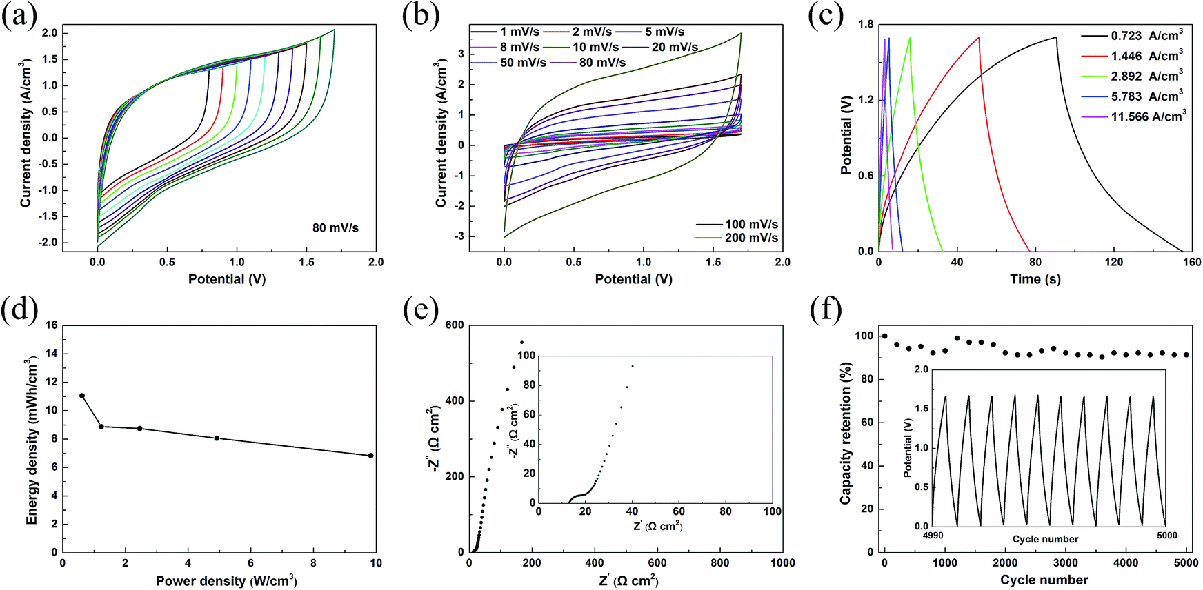
To further investigate the performance of the asymmetric supercapacitor fabricated with screen-printed MWCNTs–MnO2 anode (mass density of 0.4 mg cm−2) and well matched MWCNTs–MoO3 cathode (mass density of 0.6 mg cm−2), a variety of electrochemical measurements were performed using two electrode configurations. The CV measurements indicated that the device exhibited a stable potential window up to 1.7 V (Fig. 6a). The large potential window means a high energy density, which is a major advantage compared to common symmetric supercapacitors and a very important factor to meet the demands of application. As shown in Fig. 6b, the asymmetric supercapacitor had well symmetrical and near rectangular CV curves at the potential window of 0–1.7 V, indicating that the device also had good capacitance performance. Good linear profiles of GCD curves with different current densities (Fig. 6c) further confirmed the perfect electrochemical behaviour of the device. The asymmetric supercapacitor showed a high energy of 11.04 mW h cm−3 at a power density of 614.6 mW cm−3. Moreover, a high power density of 9.8 W cm−3 was obtained, and the energy density was still as high as 6.83 mW h cm−3 at a discharge current density of 11.566 A cm−3 (Fig. 6d). It is notable that the highest E and P of this ASC are much higher than those in previous reports.42,43 Fig. 6e presents the impedance spectrum of the as-fabricated device that exhibited a negligible 45° Warburg region and the ESR value (13 Ω) of the device, indicating the fast ion transport at the active material–electrolyte interface. The impedance spectrum becomes almost a vertical line, wherein the imaginary part of impedance increases dramatically in the low frequency range, showing the perfect capacitive behaviour of ion diffusion in the electrode materials. The long-term cycle stability was measured by GCD at a current density of 1.928 A cm−3 for 5000 cycles and the result is shown in Fig. 6f. The capacitance only showed slight fluctuations in the whole process. The capacity retention was 91.3% after 5000 cycles, which is higher than in previous reports.44,45 This implies the good charge–discharge reversibility of the device.
 | ||
| Fig. 6 Electrochemical performances of the ASC. (a) CV curves of the device at different potential windows, the scan rate is 80 mV s−1. (b) CV curves of the device at different scan rate. (c) Galvanostatic discharge curves of the device at different current densities. (d) Energy and power density plot. (e) Nyquist plot. (f) Cycle life, inset shows the GCD curve from 4990th to 5000th. | ||
Conclusions
Highly flexible conductive electrodes were successfully prepared by screen printing carbon nanoparticle ink on various substrates. The flexible electrodes showed good stability during the bending test and could act as a foldable electric circuit. An asymmetric supercapacitor was fabricated by assembling a screen printed MWCNTs–MnO2 anode and MWCNTs–MoO3 cathode. The supercapacitor has a wide operating potential window of 1.7 V and exhibited excellent electrochemical performance, e.g. a high density of 11.04 mW h cm−3 at a power density of 614.6 mW cm−3 and a high retained ratio ∼91.3% of its initial capacitance after 5000 cycles. The screen-printing, acting as a versatile, simple, fast, and cost-effective printing method, can be fully integrated with the fabrication process in current printed electronics and has potential applications for energy storage.Acknowledgements
This study was supported by the National Natural Science Foundation of china (11204093, 11374110), the Overseas Master Program (MS2011HZKJ043), and the Fundamental Research Funds for the Central Universities (HUST: 2014TS124). Y. H. G would like to thank Prof. Zhong-Lin Wang for the support of experimental facilities in WNLO of HUST.Notes and references
- L. S. Zhou, A. Wanga, S. C. Wu, J. Sun, S. Park and T. N. Jackson, Appl. Phys. Lett., 2006, 88, 3 Search PubMed.
- Y. Chen, J. Au, P. Kazlas, A. Ritenour, H. Gates and M. McCreary, Nature, 2003, 423, 136 CrossRef CAS PubMed.
- B. D. Braaten, S. Roy, S. Nariyal, M. Al Aziz, N. F. Chamberlain, I. Irfanullah, M. T. Reich and D. E. Anagnostou, IEEE Trans. Antennas Propag., 2013, 61, 655–665 CrossRef.
- A. Rida, L. Yang, R. Vyas and M. M. Tentzeris, IEEE Trans. Antennas Propag., 2009, 51, 13–23 CrossRef.
- L. Huang, Y. Huang, J. Liang, X. Wan and Y. Chen, Nano Res., 2011, 4, 675–684 CrossRef CAS.
- V. Marin, E. Holder, M. M. Wienk, E. Tekin, D. Kozodaev and U. S. Schubert, Macromol. Rapid Commun., 2005, 26, 319–324 CrossRef CAS PubMed.
- L. Catarinucci, S. Tedesco and L. Tarricone, IEEE Sens. J., 2013, 13, 783–791 CrossRef.
- H. Hu, K. Zhang, S. Li, S. Jia and C. Ye, J. Mater. Chem. A, 2014, 2, 20916–20922 CAS.
- L. Fan, N. Zhang and K. Sun, Chem. Commun., 2014, 50, 6789–6792 RSC.
- D. Pech, M. Brunet, P.-L. Taberna, P. Simon, N. Fabre, F. Mesnilgrente, V. Conedera and H. Durou, J. Power Sources, 2010, 195, 1266–1269 CrossRef CAS PubMed.
- C. Guillen and J. Herrero, Opt. Commun., 2009, 282, 574–578 CrossRef CAS PubMed.
- C. Wang, C. Wang and Y. Mao, Acta Photonica Sin., 2013, 42, 812–816 CrossRef CAS.
- L. G. de Arco, Y. Zhang, C. W. Schlenker, K. Ryu, M. E. Thompson and C. W. Zhou, ACS Nano, 2010, 4, 2865–2873 CrossRef PubMed.
- X. Xiao, X. Peng, H. Jin, T. Li, C. Zhang, B. Gao, B. Hu, K. Huo and J. Zhou, Adv. Mater., 2013, 25, 5091–5097 CrossRef CAS PubMed.
- M. Berggren, D. Nilsson and N. D. Robinson, Nat. Mater., 2007, 6, 3–5 CrossRef CAS PubMed.
- H. Yan, Z. H. Chen, Y. Zheng, C. Newman, J. R. Quinn, F. Dotz, M. Kastler and A. Facchetti, Nature, 2009, 457, 679–686 CrossRef CAS PubMed.
- F. C. Krebs, Sol. Energy Mater. Sol. Cells, 2009, 93, 394–412 CrossRef CAS PubMed.
- D. A. Pardo, G. E. Jabbour and N. Peyghambarian, Adv. Mater., 2000, 12, 1249–1252 CrossRef CAS.
- D. S. Hecht, L. Hu and G. Irvin, Adv. Mater., 2011, 23, 1482–1513 CrossRef CAS PubMed.
- A. A. Argun, A. Cirpan and J. R. Reynolds, Adv. Mater., 2003, 15, 1338–1341 CrossRef CAS PubMed.
- G. Eda, G. Fanchini and M. Chhowalla, Nat. Nanotechnol., 2008, 3, 270–274 CrossRef CAS PubMed.
- K. S. Kim, Y. Zhao, H. Jang, S. Y. Lee, J. M. Kim, K. S. Kim, J.-H. Ahn, P. Kim, J.-Y. Choi and B. H. Hong, Nature, 2009, 457, 706–710 CrossRef CAS PubMed.
- D. C. Hyun, M. Park, C. Park, B. Kim, Y. Xia, J. H. Hur, J. M. Kim, J. J. Park and U. Jeong, Adv. Mater., 2011, 23, 2946–2950 CrossRef CAS PubMed.
- L. Hu, H. S. Kim, J.-Y. Lee, P. Peumans and Y. Cui, ACS Nano, 2010, 4, 2955–2963 CrossRef CAS PubMed.
- I. E. Stewart, A. R. Rathmell, L. Yan, S. Ye, P. F. Flowers, W. You and B. J. Wiley, Nanoscale, 2014, 6, 5980–5988 RSC.
- F. Guo, H. Azimi, Y. Hou, T. Przybilla, M. Hu, C. Bronnbauer, S. Langner, E. Spiecker, K. Forberich and C. J. Brabec, Nanoscale, 2015, 7, 1642–1649 RSC.
- Y. Zhao, Y. Zhang, Y. Li, Z. He and Z. Yan, RSC Adv., 2012, 2, 11544–11551 RSC.
- S. Chung, J. Lee, H. Song, S. Kim, J. Jeong and Y. Hong, Appl. Phys. Lett., 2011, 98, 153110 CrossRef PubMed.
- M. Hösel and F. C. Krebs, J. Mater. Chem., 2012, 22, 15683–15688 RSC.
- D. Angmo, T. R. Andersen, J. J. Bentzen, M. Helgesen, R. R. Sondergaard, M. Jorgensen, J. E. Carle, E. Bundgaard and F. C. Krebs, Adv. Funct. Mater., 2015, 25, 4539–4547 CrossRef CAS PubMed.
- J. Y. Tao, N. S. Liu, J. Y. Rao, L. W. Ding, M. R. Al Bahrani, L. Y. Li, J. Su and Y. H. Gao, Nanoscale, 2014, 6, 15073–15079 RSC.
- M. F. L. e Volder, S. H. Tawfick, R. H. Baughman and A. J. Hart, Science, 2013, 339, 535–539 CrossRef PubMed.
- E. Frackowiak and F. Beguin, Carbon, 2001, 39, 937–950 CrossRef CAS.
- H. Jiang, J. Ma and C. Z. Li, Adv. Mater., 2012, 24, 4197–4202 CrossRef CAS PubMed.
- N. S. Liu, W. Z. Ma, J. Y. Tao, X. H. Zhang, J. Su, L. Y. Li, C. X. Yang, Y. H. Gao, D. Golberg and Y. Bando, Adv. Mater., 2013, 25, 4925–4931 CrossRef CAS PubMed.
- Y. Jin, H. Y. Chen, M. H. Chen, N. Liu and Q. W. Li, ACS Appl. Mater. Interfaces, 2013, 5, 3408–3416 CAS.
- J. Y. Tao, N. S. Liu, L. Y. Li and Y. H. Gao, Nanoscale, 2014, 6, 2922–2928 RSC.
- C. X. Yang, Y. L. Shi, N. S. Liu, J. Y. Tao, S. L. Wang, W. J. Liu, Y. M. Wang, J. Su, L. Y. Li, C. P. Yang and Y. H. Gao, RSC Adv., 2015, 5, 45129–45135 RSC.
- H. W. Lee, P. Muralidharan, R. Ruffo, C. M. Mari, Y. Cui and D. K. Kim, Nano Lett., 2010, 10, 3852–3856 CrossRef CAS PubMed.
- S. Wang, N. Liu, J. Tao, C. Yang, W. Liu, Y. Shi, Y. Wang, J. Su, L. Li and Y. Gao, J. Mater. Chem. A, 2015, 3, 2407–2413 CAS.
- J. P. Zheng, J. Electrochem. Soc., 2003, 150, A484–A492 CrossRef CAS PubMed.
- Z. Weng, Y. Su, D.-W. Wang, F. Li, J. Du and H.-M. Cheng, Adv. Energy Mater., 2011, 1, 917–922 CrossRef CAS PubMed.
- Y. B. Xie and X. Q. Fang, Electrochim. Acta, 2014, 120, 273–283 CrossRef CAS PubMed.
- F. Yang, M. Zhao, Q. Sun and Y. Qiao, RSC Adv., 2015, 5, 9843–9847 RSC.
- Y. Gao, Y. S. Zhou, M. Qian, H. M. Li, J. Redepenning, L. S. Fan, X. N. He, W. Xiong, X. Huang, M. Majhouri-Samani, L. Jiang and Y. F. Lu, RSC Adv., 2013, 3, 20613–20618 RSC.
Footnote |
| † Electronic supplementary information (ESI) available. See DOI: 10.1039/c5ra16724h |
| This journal is © The Royal Society of Chemistry 2015 |