Improved photocatalytic performance of self-assembled Bi/BiOBr square microflowers with square nanopetals

Qing Shan Wanga, Le Xin Song*a, Yue Tengb, Juan Xiab, Li Zhaoa and Mao Mao Ruana
aDepartment of Chemistry, University of Science and Technology of China, Jin Zhai Road 96, Hefei 230026, P. R. China. E-mail: solexin@ustc.edu.cn
bCAS Key Laboratory of Materials for Energy Conversion, Department of Materials Science and Engineering, University of Science and Technology of China, Jin Zhai Road 96, Hefei 230026, P. R. China

Received 17th August 2015 , Accepted 15th September 2015

First published on 16th September 2015


Abstract

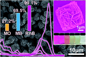
Herein we report the first example of the creation of Bi/BiOBr square microflowers with square nanopetals by a one-pot solvothermal process using ethylene glycol as both a solvent and a source of the reductant simultaneously. The square microflower material exhibited good photoelectric response and extremely high photodegradation efficiency for rhodamine B. We believe that this study represents an important advance regarding Bi-based inorganic materials.

Semiconductor materials of metal oxides have attracted great attention due to their unique photocatalysis.1,2 Conventional metal oxide photocatalysts, such as TiO2 and ZnO, are limited by their wide band gaps (3.0 eV for rutile, 3.2 eV for anatase and 3.3 eV for ZnO),3–5 only responding to UV light. Therefore, it is of great significance to develop visible-light-excited photocatalysts. It has been revealed that valence orbitals of some metal ions with nd10 or (n − 1)d10ns2 valence electronic configurations, such as Ag(I) 4d10, Sn(II) 4d105s2 and especially Bi(III) 5d106s2, can hybridize with O-2p orbitals to form a hybridized valence band,6,7 and thereby to allow oxide semiconductors of the ions to display a certain absorption in visible light range.

Bi-based semiconductors especially bismuth oxyhalides (BiOX, X = Cl ∼ I) are of immense importance for their outstanding optical, electrical properties and high stability against photocorrosion and photochemical properties.8–11 It has been reported that BiOBr has an indirect-transition band-gap which favors to reduce the recombination of photoinduced electrons and holes,9,10 and that its photo-excited activity is dependent on surface atomic structures, grain sizes and especially morphologies.11,12 Thus, various kinds of morphologies of BiOBr nano- or micro-structures including sheets, flowers and spheres have been fabricated,13–15 and various methods were adopted to couple BiOBr with other species, such as C3N4, ZnFe2O4, Bi2WO4, Pt, Au and Ag,16–23 in order to increase the conversion efficiency of incident photons to electrons for further improving its photocurrents.24,25 Recently, a few works have reported a significant enhancement of photocatalytic efficiency due to a composite of BiOBr with Bi.26,27 However, the Bi/BiOBr (BBOB) composites still have some problems such as relatively large grain sizes and nonuniform grain-size distributions, irregular shapes, diverse surfaces, and especially residues from chemical syntheses.

Taken together, these observations encourage us to develop a useful method coupling Bi with BiOBr to create a novel microstructure for enhancing photocatalytic efficiency. This is the aim of this paper. To achieve this goal, we adopted a simple one-pot solvothermal synthesis involving ethylene glycol (EG, 30 mL) as solvent, Bi(NO3)3·5H2O (0.484 g, 1 mmol) as Bi source, and cetyltrimethylammonium bromide (CTAB, 0.729 g, 2 mmol) as Br source using a sealed Teflon-lined stainless steel autoclave (50 mL) at 433 K for 12 h. Our results indicated that a grey self-assembled BBOB-1 square microflower crystal with square nanopetals having highly uniform dimensions was successfully constructed (Fig. 1), and the square microflowers presented high photocatalytic selectivity for a group of dyes: rhodamine B (RhB), methylene blue (MB) and methyl orange (MO). To the best of our knowledge, this is the first example of a BBOB composite constructed by a partial in situ reduction of BiOBr using EG as both a solvent and a source of the reductant acetaldehyde. Interestingly, the square microflower crystal represents a very rare form of microstructures. It is thus to be expected that this would attract much attention particularly in Bi-based semiconductor materials.


image file: c5ra16571g-f1.tif
Fig. 1 The XRD pattern (a), FE-SEM images (b and c), TEM image (d), SAED pattern (e) and HR-TEM image (f) of the BBOB-1.

Fig. 1a shows the XRD pattern of the BBOB-1. All of the diffraction peaks are in perfect agreement with both the tetragonal phase of BiOBr [JCPDS, 78-0348; space group P4/nmm (129); a = 3.923 Å and c = 8.105 Å]28 and the hexagonal phase of Bi [JCPDS, 85-1331; space group Rm (166); a = 4.533 Å and c = 11.79 Å].29 No impurity was found, and the sharp diffraction lines indicate that the crystal has a high degree of crystallinity.

The field emission scanning electron microscope (FE-SEM) of the BBOB-1 in Fig. 1b illustrates a large scale and uniform appearance with almost monodisperse size distribution. The magnified image in Fig. 1c shows that the particle looks like a square flower (side length, 4–5 μm) with square nanopetals (side length, 1–2 μm; thickness, 60 nm). Fig. 1d is the transmission electron microscopy (TEM) image of a single microflower with a regular and clear square structure. The selected-area electron diffraction (SAED, Fig. 1e) pattern taken from an edge of the microflower demonstrated the single-crystallinity of the BiOBr. As can be seen in the high-resolution TEM (HR-TEM, Fig. 1f) pattern from the edge of the same microflower as the SAED pattern, there are two kinds of lattice fringes with lattice spacings of 0.236 nm and 0.353 nm, corresponding to the (104) planes of the hexagonal Bi and the (101) planes of the tetragonal BiOBr, respectively. Thermogravimetry (TG, Fig. S1) and X-ray photoelectron spectroscopy (XPS, Fig. S2) analyses further confirmed that the molar ratio of Bi to BiOBr (MRBB) is about 1[thin space (1/6-em)]:[thin space (1/6-em)]10 in the square microflower material.

In order to elucidate the formation process of the square-flowers, we investigated the influence of reaction conditions: (i) time (t, 3, 9, 12 and 24 h), (ii) temperature (T, 363, 413, 433 and 453 K) and (iii) initial concentration ratio (ICR, 1[thin space (1/6-em)]:[thin space (1/6-em)]3, 1[thin space (1/6-em)]:[thin space (1/6-em)]2, 1[thin space (1/6-em)]:[thin space (1/6-em)]1 and 1[thin space (1/6-em)]:[thin space (1/6-em)]0) of Bi to Br. The three series of composite materials consisted of Bi and BiOBr were obtained. The results are illustrated in Fig. 2.


image file: c5ra16571g-f2.tif
Fig. 2 Partial XRD patterns of the BiOBr, Bi/BiOBr composites and Bi obtained at different reaction conditions: t (the first row), T (the second row) and ICR (the third row). The relative amount of Bi in the composites was roughly estimated by the relative intensity of the characteristic diffraction peak of Bi at 27.2°, which was denoted by the red arrows. Entire XRD patterns in the range of 10–80° were shown in Fig. S3–S11.

First, we noticed that all the three reaction parameters (t, T and ICR) can be used to control the molar ratio of Bi to BiOBr based on the diffraction intensity of Bi and BiOBr. As shown in Fig. 2, the content of Bi in the composite was increased with the increase of t and T as well as the decrease of ICR. In particular, only metal Bi (Bi-1, 0.137 g, 65.6%) was formed in the absence of CTAB, and only BiOBr (BiOBr-1, 0.294 g, 96.4%) was observed when either the t was decreased to 3 h or the T was decreased to 363 K (BiOBr-2, 0.296 g, 97.1%). These observations clearly reveal that BiOBr was firstly produced and subsequently further reduced to Bi, as described in eqn (1)–(4).

In eqn (1), Bi(NO3)3 was hydrolyzed into BiONO3 in the presence of water from the hydrate of the Bi(III) salt.30 Then, the BiONO3 was reacted with CTAB to generate BiOBr (eqn (2)).31 Meanwhile, some of EG molecules were reduced into acetaldehyde (eqn (3)) at a high temperature (above 413 K),32 leading to the reduction of the BiOBr and/or BiONO3 to Bi (eqn (4) and (5)).33 The HR-TEM image in Fig. 1f clearly shows a tight combination of Bi and BiOBr on the surface of the BBOB-1, suggesting that the metal Bi came from the in situ reduction of BiOBr.26,34–36 It is worth noting that only metal Bi can be found in the absence of CTAB, implying complete reduction of BiONO3 to Bi. In other words, BiONO3 is an unstable state in EG solvent, having a lower stability than BiOBr in the light of the composition of the several series composites (see Fig. 2). Therefore, the MRBB in the composites mainly depends on a transition from BiOBr to Bi, the latter being a stable state in EG at such a temperature. Therefore, the longer t, the higher T, and the lower ICR, the greater the proportion of Bi in the composites. This feature is very significant because it proves that the composition of a metal and its oxyhalide in their composites can be easily modulated by adjusting the three reaction parameters.

 
Bi(NO3)3 + H2O ⇀ BiONO3 + 2HNO3 (1)
 
BiONO3 + C16H33(CH3)3NBr ⇀ BiOBr + C16H33(CH3)3NNO3 (2)
 
EG ⇀ CH3CHO + H2O (3)
 
3CH3CHO + 2BiOBr + H2O ⇀ 3CH3COOH + 2Bi + 2HBr (4)
 
3CH3CHO + 2BiONO3 + H2O ⇀ 3CH3COOH + 2Bi + 2HNO3 (5)

Second, we observed that the reaction parameters could produce completely different effects on the surface structure of the composites according to the SEM images in Fig. 3. Initially, it can be clearly seen that the t plays an important role in regulating the self-assembly of small nanoplates. For example, a spontaneous structural transformation occurs from a compressed tetragonal prism structure for 3 (BiOBr-1) and 9 h (BBOB-2), to a square flower structure of the BBOB-1 associated with nanoplates (Fig. 1) for 12 h, and to a multilayer square plate structure for 24 h (BBOB-3). More importantly, the content of metallic Bi in the composites is closely related with the t since the MRBB increases in the order: BBOB-2 (1[thin space (1/6-em)]:[thin space (1/6-em)]18, Fig. S12) < BBOB-1 (1[thin space (1/6-em)]:[thin space (1/6-em)]10) < BBOB-3 (1[thin space (1/6-em)]:[thin space (1/6-em)]7, Fig. S13). These results signify that both the shape and the composition of the grains can be easily controlled by adjusting the t. In this way, the structure transformation could be envisaged as a “grain coarsening” process, in which the formation, composition and structure of the square flowers is regulated. Further, by comparing the shape of the composites obtained using different ICRs, we noticed that CTAB can act as a morphology-directing agent facilitating self-assembly of the nanoparticles (ICR, 1[thin space (1/6-em)]:[thin space (1/6-em)]3) to generate the square flowers (ICR, 1[thin space (1/6-em)]:[thin space (1/6-em)]2), microspheres (ICR, 1[thin space (1/6-em)]:[thin space (1/6-em)]1) and irregular particles (ICR, 1[thin space (1/6-em)]:[thin space (1/6-em)]0), as seen from Fig. 3. We suggest that the role of CTAB may be associated with the formation of surface active ionic liquids in EG solvent. Different concentrations of CTAB are likely to lead to different interaction intensities between the cationic surface active ions from CTAB and the composites, thereby creating different appearances. Finally, we noted that the equilibrium of such a form based on the interaction type could be easily disturbed even at either slightly higher (453 K) or lower (363 and 413 K) T, resulting in the generation of irregular surfaces.


image file: c5ra16571g-f3.tif
Fig. 3 SEM images of the BiOBr, Bi/BiOBr and Bi materials obtained at different reaction conditions: t (the red arrow), T (the blue arrow) and ICR (the green arrow). Large scale SEM images were shown in Fig. S3–S11.

The surface area and porous structure of the BBOB-1 were studied by gas adsorption/desorption measurements in liquid nitrogen. The sorption isotherm (Fig. S14) exhibits a similar type IV pattern37 with a small hysteresis loop at a relative pressure range of 0.43–0.96, implying some mesoporous characteristics. Also, our data show that the BBOB-1 has a Brunauer–Emmett–Teller (BET)38 specific surface area of 9.75 m2 g−1 and an average pore diameter of 15.9 nm. The UV-Vis diffuse reflectance spectroscopy (Fig. S15) was used to examine the electronic structure of this material. Its optical bandgap was determined to be 2.44 eV (Fig. S16) in terms of the Kubelka–Munk function,39 which is the same as that of Sn/Bi/BiOBr,26 but much lower than those obtained for BiOBr10,14 and especially for Bi/BiOCl34,35 (Table S1). It indicates that the presence of Bi may be used as a means to reduce the bandgap of BiOBr, thereby giving an absorption in a large range of wavelengths.

To demonstrate this, a time-dependent photocurrent response was performed (Fig. S17). It was shown that upon illumination the photocurrent of the square microflower material rapidly increases to a maximum of 893.9 nA (light current) and keeps unchanged with the increasing time. Moreover, when the light is turn off, the current immediately decreases to a minimum of 142.1 nA (dark current). Such a large light current, which is much higher than that of Bi/BiOCl,34 has been achieved under a low bias voltage of 0.5 V, suggesting a low recombination rate of electrons and holes. This high ratio of light current to dark current (6.3) is an indication of an effective photoelectron transfer. Additionally, the photocurrent response is reversible and stable under successive cycling, signifying that the photocurrent could easily be reproduced for each irradiation.

The large surface area, high porosity and related mesoporous microarchitectures, combined with the well-organized arrays of highly monodisperse microparticles with a relative low bandgap, should considerably improve the photocatalytic performance of BiOBr.

Fig. 4A indicates the UV-Vis absorption spectra of the RhB solutions (10 mg L−1) after being treated by the BBOB-1 (20 mg) under the natural sunlight irradiation. It is obvious that the characteristic maximum absorption band of RhB at 554 nm40 was significantly decreased with the increase of irradiation time. Most importantly, this band almost completely disappeared after 125 min of irradiation. Furthermore, we have also observed a gradual colour change from purple to colourless by a photograph (the inset of this figure). These results not only reflect the degradation process of the series solutions, but also provide information about the complete photodegradation of RhB in the presence of the BBOB-1 catalyst. The photodegradation degree (ξ, %) of RhB was determined based on eqn (6).41

 
image file: c5ra16571g-t1.tif(6)


image file: c5ra16571g-f4.tif
Fig. 4 (A) UV-Vis absorption spectra of the RhB solutions (10 mg L−1) after being treated by the BBOB-1 (20 mg) after 0 (a), 25 (b), 50 (c), 75 (d), 100 (e) and 125 (f) min of sunlight irradiation. The inset shows a colour change of the solutions from (a) to (f); (B) UV-Vis absorption spectra of the MO solutions (10 mg L−1) after being treated by the BBOB-1 (20 mg) after 0 (g) and 125 min (h) and the MB solutions (10 mg L−1) after being treated by the BBOB-1 (20 mg) after 0 (i) and 125 min (j) of sunlight irradiation. The inset shows the ξ of MO, MB and RhB at the same conditions (concentration: 10 mg L−1; the amount of BBOB-1: 20 mg; sunlight irradiation time: 125 min); (C) UV-Vis absorption spectra of the RhB solutions (10 mg L−1) after being treated by the catalysts (20 mg) after 125 min of sunlight irradiation.

In this equation, C0 and C is the initial concentration of RhB and its concentration after irradiation, respectively. Our data indicate that the ξ is 99.1% after 125 min of irradiation in the presence of the BBOB-1, and especially it can still reach 96.9% over the first five cycles (Fig. S18). Moreover, recycling experiments reveal that the catalyst exhibits a good structural stability because no change in crystal structure and surface morphology was observed after consecutive cycles (Fig. S19 and S20). Thus these observations give us a strong indication that the BBOB-1 has high photocatalytic activity, stability and sustainability for the degradation of RhB. The present results are comparable to the best and most recent results obtained from synthesized materials.14,26

Further, we found that a low ξ (69.5%) for MB and a very low ξ (27.2%) for MO were obtained when RhB was replaced by MB and MO after 125 min of irradiation (Fig. 4B). It implies an exceptionally high selectivity of the catalyst for the dyes. This is a very significant and interesting phenomenon and is extremely important in the structural recognition of different organic dyes. Of these pollutants, RhB and MB are cationic dyes,42,43 whereas MO is an anionic dye.44 Therefore, the catalytic selectivity toward cationic dyes probably owing to favorable electrostatic interactions. This should be a clear indication that the surface of the BBOB-1 square flowers present partially negative charges.

Finally, we compared the catalytic activities of free Bi and BiOBr with those of the BBOB materials under the same photocatalytic conditions. As shown in Fig. 4C, there are two important features to note.

First, the catalytic activities of both the BBOB-2 tetragonal prisms (ξ, 84.7%) and the BBOB-3 multilayer square plates (ξ, 80.6%) are much lower than that of the BBOB-1 square flowers for the photodegradation of RhB, with an increase order BBOB-3 < BBOB-2 < BBOB-1. The most probable explanation is that the result is associated with the composition and surface structure of the materials. A moderate ratio of Bi to BiOBr in the materials would be beneficial to charge separation and transfer, which have an advantageous effect on the photocatalytic property. This result is in agreement with the report of other studies.36,45 Further, our data demonstrated that the BET specific surface areas of the BBOB-2 (8.07 m2 g−1, Fig. S21) and BBOB-3 (5.12 m2 g−1, Fig. S22) are smaller than that of the BBOB-1, having the same order as the catalytic activities. The larger surface area may be one reason that the BBOB-1 gives a stronger photocurrent response (Fig. S23) and a higher visible absorption (Fig. S15). For instance, the ratios of light current to dark current and the optical bandgaps of the BBOB-1 and BBOB-2 are 6.3 and 3.7, and 2.44 and 2.62 eV (Fig. S16), respectively. It is worthy of note that the BBOB-3 exhibits a very low ratio (1.8) of light current to dark current, and its optical bandgap could not be determined. These results allow us to conclude that the relatively large surface area plays a crucial role in improving photocurrent responses and lowering bandgaps (leading to a lower Schottky barrier height and an output current increase)46 in the photoelectrochemical process, thereby enhancing catalytic efficiency.

Second, both Bi-1 and BiOBr-1 exhibit much lower catalytic activities than the BBOB materials for the photodegradation of RhB at the same conditions. For instance, the values of ξ in the cases of the Bi-1 and BiOBr-1 are 20.9 and 70.9%, respectively, as seen from Fig. 4C. This result strongly supports the suggestion that such a composite between Bi and BiOBr has greatly improved the catalytic performance of BiOBr since metallic Bi only presents a very low catalytic ability. Similar phenomena have been observed in several recent studies.26,27,34–36

Additionally, a series of trapping experiments were carried out to demonstrate the active species during the photocatalytic process (Fig. S24). Our results implied that the holes (h+) and superoxide radical ions (˙O2) are the main active species for the BBOB-1 to degrade RhB in aqueous solution under visible light irradiation.

Here, we would like to present a possible degradation process of the dyes to explain the improved photocatalytic activity in terms of our data. As illustrated in Fig. 5, under visible light irradiation, the BiOBr in the composite was photoexcited to generate electrons in the conduction band (CB) and h+ in the valence band (VB, eqn (7)). A long-distance intervalence electron transfer can occur from the excited BiOBr to Bi,26 thereby causing electron accumulation at Bi interfaces. This process is beneficial to the separation of electron–hole pairs. Highly active oxidants such as ˙O2 were produced from oxygen by the photo-induced electrons on the Bi (eqn (8)). The dye molecules were first reacted with h+ to generate corresponding cation radicals (like ˙RhB+, eqn (9)). Then, the cation radicals were reacted with the active ˙O2, and finally degraded into inorganic species such as CO2 and H2O (eqn (10)). Undoubtedly, the synergetic effect of Bi and BiOBr in electron transfer is a key factor for the improved results. Moreover, the photosensitization of the dyes under visible light may also be a simultaneous degradation pathway.47


image file: c5ra16571g-f5.tif
Fig. 5 Possible schematic illustration of the photocatalytic selectivity and superiority of BBOB-1.

We consider that the square structure can provide more possibilities for leading to the separation of photogenerated electrons in photocatalysis, due to its geometrical morphology with exposed active facets.48 On the other hand, the square microstructure has a relatively large BET surface area, resulting in more unsaturated surface coordination sites exposed to the ambient and an easier transfer of electrons and holes. These may be why the square flower material exhibits improved performance in photocatalytic degradation of dyes.49

 
BiOBr + ⇀ BiOBr (h+ + e) (7)
 
e + O2 ⇀ ˙O2 (8)
 
RhB + h+ ⇀ ˙RhB+ (9)
 
˙O2 + ˙RhB+ ⇀ CO2 + H2O (10)

In summary, a novel monodisperse Bi/BiOBr square flower microstructure was successfully fabricated through a facile one-step solvothermal route utilized EG as both a solvent and a source of the reductant simultaneously. Importantly, the composition and structure of Bi and BiOBr in the composites can be readily tuned by adjusting any one of the reaction parameters: t, T and ICR. Further, the square flower material with a relatively large surface area and a moderate MRBB seems to exhibit an improved photocatalytic activity for RhB. Overall, this work represents an important step toward the structural functional characterization of Bi-based semiconductor materials and the development of controllable synthesis of micro/nanostructures.

Acknowledgements

This project was supported by NSFC (No. 21071139) and Natural Science Foundation of Anhui Province (No. 1508085MB30).

Notes and references

  1. (a) S. U. Khan, M. Al-Shahry and W. B. Ingler, Science, 2002, 297, 2243–2245 CrossRef CAS PubMed; (b) X. B. Chen, S. H. Shen, L. J. Guo and S. S. Mao, Chem. Rev., 2010, 110, 6503–6570 CrossRef CAS PubMed.
  2. H. B. Wu, H. H. Hng and X. W. D. Lou, Adv. Mater., 2012, 24, 2567–2571 CrossRef CAS PubMed.
  3. (a) G. M. Wang, H. Y. Wang, Y. C. Ling, Y. C. Tang, X. Y. Yang, R. C. Fitzmorris, C. C. Wang, J. Z. Zhang and Y. Li, Nano Lett., 2011, 11, 3026–3033 CrossRef CAS PubMed; (b) K. Woan, G. Pyrgiotakis and W. Sigmund, Adv. Mater., 2009, 21, 2233–2239 CrossRef CAS PubMed.
  4. (a) D. C. Pan, N. N. Zhao, Q. Wang, S. C. Jiang, X. L. Ji and L. J. An, Adv. Mater., 2005, 17, 1991–1995 CrossRef CAS PubMed; (b) H. B. Yin, Y. J. Wada, T. Kitamura, S. Kambe, S. Murasawa, H. Mori, T. Sakata and S. Yanagida, J. Mater. Chem., 2001, 11, 1694–1703 RSC.
  5. S. M. Hatch, J. Briscoe and S. Dunn, Adv. Mater., 2013, 25, 867–871 CrossRef CAS PubMed.
  6. H. G. Kim, D. W. Hwang and J. S. Lee, J. Am. Chem. Soc., 2004, 126, 8912–8913 CrossRef CAS PubMed.
  7. (a) H. F. Cheng, B. B. Huang and Y. Dai, Nanoscale, 2014, 6, 2009–2026 RSC; (b) Y. Bi, S. Ouyang, N. Umezawa, J. Cao and J. Ye, J. Am. Chem. Soc., 2011, 133, 6490–6492 CrossRef CAS PubMed.
  8. (a) X. Xiao and W. D. Zhang, J. Mater. Chem., 2010, 20, 5866–5870 RSC; (b) B. Zhang, G. B. Ji, M. Gondal, Y. S. Liu, X. M. Zhang, X. F. Chang and N. W. Li, J. Nanopart. Res., 2013, 15, 1–9 Search PubMed.
  9. Y. Wang, Z. Q. Shi, C. M. Fan, X. W. Wang, X. G. Hao and Y. Q. Chi, J. Solid State Chem., 2013, 199, 224–229 CrossRef CAS PubMed.
  10. X. Zhang, Z. H. Ai, F. L. Jia and L. Z. Zhang, J. Phys. Chem. C, 2008, 112, 747–753 CAS.
  11. (a) J. Jiang, K. Zhao, X. Y. Xiao and L. Z. Zhang, J. Am. Chem. Soc., 2012, 134, 4473–4476 CrossRef CAS PubMed; (b) Z. X. Pei, L. Y. Ding, H. Lin, S. X. Weng, Z. Y. Zheng, Y. D. Hou and P. Liu, J. Mater. Chem. A, 2013, 1, 10099–10102 RSC; (c) S. X. Weng, Z. X. Pei, Z. Y. Zheng, J. Hu and P. Liu, ACS Appl. Mater. Interfaces, 2013, 5, 12380–12386 CrossRef CAS PubMed.
  12. (a) H. Li, J. Shang, Z. H. Ai and L. Z. Zhang, J. Am. Chem. Soc., 2015, 137, 6393–6399 CrossRef CAS PubMed; (b) L. S. Zhong, J. S. Hu, L. J. Wan and W. G. Song, Chem. Commun., 2008, 1184–1186 RSC; (c) M. Zhou, H. B. Wu, J. Bao, L. Liang, X. W. D. Lou and Y. Xie, Angew. Chem., Int. Ed., 2013, 52, 8579–8583 CrossRef CAS PubMed.
  13. J. Chen, M. L. Guan, W. Z. Cai, J. J. Guo, C. Xiao and G. K. Zhang, Phys. Chem. Chem. Phys., 2014, 16, 20909–20914 RSC.
  14. (a) Y. N. Huo, J. Zhang, M. Miao and Y. Jin, Appl. Catal., B, 2012, 111, 334–341 CrossRef PubMed; (b) J. Y. Xiong, Q. S. Dong, T. Wang, Z. B. Jiao, G. X. Lu and Y. P. Bi, RSC Adv., 2013, 4, 583–586 RSC.
  15. (a) J. Zhang, F. J. Shi, J. Lin, D. F. Chen, J. M. Gao, Z. X. Huang, X. X. Ding and C. C. Tang, Chem. Mater., 2008, 20, 2937–2941 CrossRef CAS; (b) J. X. Xia, S. Yin, H. M. Li, H. Xu, L. Xu and Y. G. Xu, Dalton Trans., 2011, 40, 5249–5258 RSC.
  16. L. Q. Ye, J. Y. Liu, Z. Jiang, T. Y. Peng and L. Zan, Appl. Catal., B, 2013, 142, 1–7 Search PubMed.
  17. J. Fu, Y. L Tian, B. B. Chang, F. N. Xi and X. P. Dong, J. Mater. Chem., 2012, 22, 21159–21166 RSC.
  18. L. Kong, Z. Jiang, T. C. Xiao, L. F. Lu, M. O. Jones and P. P. Edwards, Chem. Commun., 2011, 47, 5512–5514 RSC.
  19. Y. L. Li, Y. M. Liu, J. S. Wang, E. Uchaker, Q. F. Zhang, S. B. Sun, Y. X. Huang, J. Y. Li and G. Z. Cao, J. Mater. Chem. A, 2013, 1, 7949–7956 CAS.
  20. Y. Q. Jia, Y. X. Yang, Y. N. Guo, W. Guo, Q. Qin, X. Yang and Y. H. Guo, Dalton Trans., 2015, 44, 9439–9449 RSC.
  21. W. J. Kim, D. Pradhan, B. K. Min and Y. Sohn, Appl. Catal., B, 2014, 147, 711–725 CrossRef CAS PubMed.
  22. L. F. Lu, L. Kong, Z. Jiang, H. H. C. Lai, T. C. Xiao and P. P. Edwards, Catal. Lett., 2012, 142, 771–778 CrossRef CAS.
  23. H. F. Cheng, B. B. Huang, P. Wang, Z. Y. Wang, Z. Z. Lou, J. P. Wang, X. Y. Qin, X. Y. Zhang and Y. Dai, Chem. Commun., 2011, 47, 7054–7056 RSC.
  24. J. X. Xia, J. Di, S. Yin, H. Xu, J. Zhang, Y. G. Xu, L. Xu, H. M. Li and M. X. Ji, RSC Adv., 2014, 4, 82–90 RSC.
  25. J. Di, J. X. Xia, S. Yin, H. Xu, M. Q. He, H. M. Li, L. Xu and Y. P. Jiang, RSC Adv., 2013, 3, 19624–19631 RSC.
  26. X. M. Zhang, G. B. Ji, Y. S. Liu, X. G. Zhou, Y. Zhu, D. N. Shi, P. Zhang, X. Z. Cao and B. Y. Wang, Phys. Chem. Chem. Phys., 2015, 17, 8078–8086 RSC.
  27. Z. S. Liu and B. T. Wu, Mater. Sci. Semicond. Process., 2015, 31, 68–75 CrossRef CAS PubMed.
  28. (a) Y. F. Fang, W. H. Ma, Y. P. Huang and G. W. Cheng, Chem.–Eur. J., 2013, 19, 3224–3229 CrossRef CAS PubMed; (b) Z. K. Xu, L. Han, B. H. Lou, X. W. Zhang and S. J. Dong, Nanoscale, 2014, 6, 145–150 RSC.
  29. Q. Wang, C. L. Jiang, D. H. Cao and Q. W. Chen, Mater. Lett., 2007, 61, 3037–3040 CrossRef CAS PubMed.
  30. H. Zhang, Y. J. Ji, X. Y. Ma, J. Xu and D. R. Yang, Nanotechnology, 2003, 14, 974–977 CrossRef CAS.
  31. G. F. Li, F. Qin, H. Yang, Z. Lu, H. Z. Sun and R. Chen, Eur. J. Inorg. Chem., 2012, 2012, 2508–2513 CrossRef CAS PubMed.
  32. J. Y. Zheng, X. Wang, W. Li, Z. Cao, H. Wang, C. Zhang, W. G. Song, Y. Ma and J. Yao, CrystEngComm, 2012, 14, 7616–7620 RSC.
  33. (a) D. Ma, J. Zhao, Y. Zhao, X. Hao and Y. Lu, Chem. Eng. J., 2012, 209, 273–279 CrossRef CAS PubMed; (b) C. Chang, L. Y. Zhu, Y. Fu and X. L. Chu, Chem. Eng. J., 2013, 233, 305–314 CrossRef CAS PubMed.
  34. S. X. Weng, B. B. Chen, L. Y. Xie, Z. Y. Zheng and P. Liu, J. Mater. Chem. A, 2013, 1, 3068–3075 CAS.
  35. Y. Yu, C. Y. Cao, H. Liu, P. Li, F. F. Wei, Y. Jiang and W. G. Song, J. Mater. Chem. A, 2014, 2, 1677–1681 CAS.
  36. J. J. Hu, G. Q. Xu, J. W. Wang, J. Lv, X. Y. Zhang, Z. X. Zheng, T. Xie and Y. C. Wu, New J. Chem., 2014, 38, 4913–4921 RSC.
  37. (a) J. Beck, J. Vartuli, W. Roth, M. Leonowicz, C. Kresge, K. Schmitt, C. Chu, D. H. Olson and E. Sheppard, J. Am. Chem. Soc., 1992, 114, 10834–10843 CrossRef CAS; (b) T. Zhu, J. S. Chen and X. W. D. Lou, J. Phys. Chem. C, 2012, 116, 6873–6878 CrossRef CAS.
  38. S. Brunauer, P. H. Emmett and E. Teller, J. Am. Chem. Soc., 1938, 60, 309–319 CrossRef CAS.
  39. G. Kortüm, W. Braun and G. Herzog, Angew. Chem., Int. Ed., 1963, 2, 333–341 CrossRef PubMed.
  40. D. Chen and J. H. Ye, Adv. Funct. Mater., 2008, 18, 1922–1928 CrossRef CAS PubMed.
  41. (a) Z. K. Yang, L. X. Song, Y. Teng and J. Xia, J. Mater. Chem. A, 2014, 2, 20004–20009 RSC; (b) J. Xia, L. X. Song, W. Liu, Y. Teng, Q. S. Wang, L. Zhao and M. M. Ruan, RSC Adv., 2015, 5, 12015–12024 RSC.
  42. M. Cheng, W. Ma, J. Li, Y. Huang, J. Zhao, Y. X. Wen and Y. Xu, Environ. Sci. Technol., 2004, 38, 1569–1575 CrossRef CAS.
  43. (a) A. X. Yan, S. Yao, Y. G. Li, Z. M. Zhang, Y. Lu, W. L. Chen and E. B. Wang, Chem.–Eur. J., 2014, 20, 6927–6933 CrossRef CAS PubMed; (b) Y. Shimizu, S. Tanigawa, Y. Saito and T. Nakamura, J. Appl. Polym. Sci., 2005, 96, 2423–2428 CrossRef CAS PubMed.
  44. (a) S. Kansal, M. Singh and D. Sud, J. Hazard. Mater., 2007, 141, 581–590 CrossRef CAS PubMed; (b) R. Gong, J. J. Ye, W. Dai, X. Y. Yan, J. Hu, X. Hu, S. Li and H. Huang, Ind. Eng. Chem. Res., 2013, 52, 14297–14303 CrossRef CAS.
  45. (a) Y. J. Wang, R. Shi, J. Lin and Y. F. Zhu, Energy Environ. Sci., 2011, 4, 2922–2929 RSC; (b) Y. Peng, M. Yan, Q. G. Chen, C. M. Fan, H. Y. Zhou and A. W. Xu, J. Mater. Chem. A, 2014, 2, 8517–8524 RSC; (c) J. X. Xia, J. Di, S. Yin, H. Xu, J. Zhang, Y. G. Xu, L. Xu, H. M. Li and M. X. Ji, RSC Adv., 2014, 4, 82–90 RSC.
  46. M. H. Sheikhi, Solid-State Electron., 2009, 53, 497–503 CrossRef PubMed.
  47. (a) J. M. Wu and T. W. Zhang, J. Photochem. Photobiol., A, 2004, 162, 171–177 CrossRef CAS; (b) J. Y. Xiong, G. Cheng, G. F. Li, F. Qin and R. Chen, RSC Adv., 2011, 1, 1542–1553 RSC.
  48. (a) Y. Zhou, Z. P. Tian, Z. Y. Zhao, Q. Liu, J. H. Kou, X. Chen, J. Gao, S. C. Yan and Z. G. Zou, ACS Appl. Mater. Interfaces, 2011, 3, 3594–3601 CrossRef CAS PubMed; (b) D. J. Mao, X. M. Lü, Z. F. Jiang, J. M. Xie, X. F. Lu, W. Wei and A. S. Hossain, Mater. Lett., 2014, 118, 154–157 CrossRef CAS PubMed.
  49. (a) J. Zhang, F. Shi, J. Lin, D. Chen, J. Gao, Z. Huang, X. Ding and C. Tang, Chem. Mater., 2008, 20, 2937–2941 CrossRef CAS; (b) G. Cheng, J. Xiong and F. J. Stadler, New J. Chem., 2013, 37, 3207–3213 RSC; (c) G. H. Tian, Y. J. Chen, W. Zhou, K. Pan, Y. Z. Dong, C. G. Tian and H. G. Fu, J. Mater. Chem., 2011, 21, 887–892 RSC.

Footnote

Electronic supplementary information (ESI) available. See DOI: 10.1039/c5ra16571g

This journal is © The Royal Society of Chemistry 2015
Click here to see how this site uses Cookies. View our privacy policy here.