
 Open Access Article
 This Open Access Article is licensed under a
 Creative Commons Attribution 3.0 Unported Licence
Poly(ionic liquid) binders as Li+ conducting mediators for enhanced electrochemical performance†
Jung-Soo
Lee‡
a,
Ken
Sakaushi
*ab,
Markus
Antonietti
a and
Jiayin
Yuan
*a
aMax Planck Institute of Colloids and Interfaces, Colloid Chemistry Department, Am Mühlenberg 1 OT Golm, D-14476 Potsdam, Germany. E-mail: jiayin.yuan@mpikg.mpg.de
bNational Institute for Materials Science, International Center for Materials Nanoarchitectonics (MANA), 1-1 Namiki, Tsukuba, 305-0044 Ibaraki, Japan. E-mail: sakaushi.ken@nims.go.jp
First published on 30th September 2015
Abstract
A series of poly(ionic liquid)s (PILs) were used as binders for lithium-ion battery (LIB) with a LiFePO4 cathode to explore their role and benefits in a model electrochemical energy storage system. The PILs are imidazolium-based and bear different main chain structures and alkyl substituents. The results nicely show that PILs both improve the cycling stability and specific capacity. When carefully designed, they especially exhibited a usually high electrochemical stability against oxidative conditions (=4.0 vs. Li/Li+). It is found that the PIL binders together with carbon additive form very effective Li+ and electron conducting pathways in the electrode. These finding illustrate that binder with carefully designed chemical structures can have a high potential to improve the electrochemical performance even of current rechargeable battery systems. A better Li+ and electron conduction is however of general importance for a wide spectrum of electrochemical devices.
1. Introduction
Electrochemical energy storage and conversion devices, such as batteries, fuel cells, supercapacitors, but also liquid solar cells and artificial photosynthesis are attracting tremendous attention due to their active role in solving global challenges such as the change towards sustainable energy and the coupled avoidance of pollution and climate change.1 As a model, rechargeable lithium-ion batteries (LIBs) have gained extensive utilization in consumer electronics owing to their high power, energy density and low weight.2 Expansion of LIBs for next-generation technology, such as electric vehicles and large-scale-electrochemical-energy-storage however relies on further developments towards higher energy density, but also longer life-time.3,4 Adding to the current focus on design of new electrode materials and stable electrolytes at harsh conditions in batteries, only little effort has been directed to polymer binder so far. Such binder material accounts for typically 10 wt% of the electrode mass, but it effectively “glues” all powderous components, such as electrochemically active species and conductive additives, into a mechanically stable electrode to endure the operation conditions.5 The direct and indirect benefits of an improved binder thereby sum up easily to 10% efficiency and a longer lifetime, an apparently small improvement which however has to be multiplied with the some billion battery systems produced and thrown away every year.Through very limited but inspiring primary studies,6–12 it is well known that even huger effects of polymer binders on the overall performance of many electrochemical devices can be expected, particularly with respect to the resulting mechanical properties and interactions with electrolytes and active material. PVDF has been extensively utilized as a standard choice for electrodes of, among many, LIBs due to its electrochemical inertness, especially for cathodes. The disadvantages of PVDF binders are its insulating character and a relatively large amount of electrolyte swelling. As a result, the adhesion of PVDF to electrode materials deteriorates under long operational run, and an increase in contact resistance between the active material and carbon material is found.12 As lifetime enters directly the costs per stored kWh of a practical large-scale energy storage system, any lifetime improvement is valuable, and a stable operation for more than a decade is desired.13 To overcome these drawbacks, newly designed binder materials are necessary. In our opinion, next-generation binders participating in the main electrochemical reactions, but being at same time electrochemically at least as stable as PVDF, can help address those problems.
Ionic liquids (ILs) are for a long time investigated for use in several electrochemical energy storage/conversion devices, due to their favorable physical properties such as negligible vapor pressure, high ion conductivity, chemical inertness and a broad electrochemical stability.14–21 Recently, the interest on poly(ionic liquid)s (PILs) were found to be a highly attractive class of functional polymers.22–27 To our knowledge, only in a recent paper a PIL copolymer in nanoparticulate form have been examined as binder for electrode of LIBs.28 In spite of the exciting and encouraging progress reported when applied to the cathode, these nanoparticle binders were nevertheless claimed to decompose under operation. It should however be possible to avoid this degradation when the binders are correctly designed by polymer chemistry. In our recent attempt, via modifying the building unit of PIL nanoparticles, we were able to extend the cycling stability of LIBs far beyond that based on PVDF binder. Nevertheless, the complicated synthetic chemistry to PIL nanoparticles not only makes the large-scale production unconventional but also restricts a deep insight in the electrochemical process of how these binders improve the electrode performance.29
Here, we demonstrate the good performance and high stability of more easy-to-synthesize linear chain PIL binders, while trying to describe mechanistically how they assist the electrochemical reactions in LIBs. The data can be described by formation of a favorable Li+ conducting polymer interface which acts as a heterojunction at the storage material grains. At the same time, while stabilizing and connecting the carbon additives, it forms a convenient electron conductive network.
2. Experimental
2.1 Materials
1-Vinylimidazole, methylimidazole, 1,2-dimethylimidazole, ethylbromide, 4-vinylbenzyl chloride, water-soluble nonionic azo-initiator VA86 (Wake Chemicals), α,α′-azobisiso-butyrobitrile (AIBN; Aldrich 99%), and lithium bis(trifluoromethylsulfonyl)imide (TFSI; Aldrich 97%) were used as received without further purifications. All solvents used were of analytic grade.2.2 Monomer synthesis
2.3 Polymer synthesis
![[thin space (1/6-em)]](https://www.rsc.org/images/entities/char_2009.gif) :1). The beige solid was filtered off and washed with water/MeOH several times (400 mL in total). The product was dried at 80 °C under high vacuum. This monomer based-binder is anion exchanged after polymerization with same method.
:1). The beige solid was filtered off and washed with water/MeOH several times (400 mL in total). The product was dried at 80 °C under high vacuum. This monomer based-binder is anion exchanged after polymerization with same method.
2.4 Characterization methods
Thermal gravimetric analyses (TGA) were performed on a Netzsch TG209-F1 apparatus at a heating rate of 10 °C min−1. FT-IR spectra were recorded on a Varian1000 FT-IR spectrometer. Gel permeation chromatography (GPC) was performed in a NOVEMA-column using a mixture of 80% of aqueous acetate buffer solution and 20% of methanol (flow rate 1.00 mL min−1, PEO standards) and using RI detector-Optilab-DSP-Interferometric Refractometer (Wyatt-Technology). P1 paired with Br as counter anion was measured directly by GPC, while P2 and P3 bearing TFSI as counter anion underwent an anion exchange to replace TFSI with Br counter anion before measurements by GPC. For the anion exchange reaction, a solution of P2 and P3 bearing TFSI as counter anion was added dropwise into a 1 M solution of tetrabutylammonium bromide in acetone. The precipitate was soluble in water for GPC measurements.2.5 Electrochemical analysis
The electrodes were prepared by spreading on aluminium foil current collector with slurry of acetylene black (AB), PILs binders and lithium iron phosphate (LiFePO4) in N-methylpyrrolidone (NMP). The ratio was kept constant in all 80% LiFePO4, 10% AB and 10% binder material. The electrodes were dried at 80 °C for 3 h and 120 °C for 24 h. The loading of mixture was controlled at ∼2.5 mg. The electrodes were assembled in two-electrode Swagelok-type cells in an argon filled glove box (MBraun). Lithium foil was used counter electrode and glass fiber membrane was used as separator. The electrolyte solution was 1 M lithium hexafluorophosphate (LiPF6) in mixture of ethylene carbonate (EC) and dimethyl carbonate (DMC) (1:1 v/v). The cells were cycled in potential window between 2.0 and 4.0 V vs. Li/Li+ using multichannel potentiostatic/galvanostatic system (Bio-Logic). The C-rate was calculated on the basis of LiFePO4 assuming a theoretical specific capacity of 170 mA h g−1. The corrosion test for PILs binders was performed at constant potential of 4.0 V Li/Li+ for 2 weeks using ∼2 mg of binders. Electrochemical impedance spectroscopy (EIS) measurements were carried out with a frequency range from 100 mHz to 20 kHz with an amplitude of 25 mV. The fit of the experimental EIS data was carried out by using EC-Lab.
3. Results and discussion
The chemical structures of linear PIL binders tested in this study are shown in Fig. 1 and the synthetic details were given in the ESI.† P1 was prepared via conventional free radical polymerization of an ionic liquid monomer (M1) with Br− as counter anion, followed by an anion exchange reaction of the polymer to replace Br− with an electrochemically inert anion, bis(trifluoromethane sulfonyl)imide (TFSI). P2 and P3 were directly obtained via conventional free radical polymerization of the corresponding imidazolium ionic liquid monomers (M2 and M3) with TFSI as counter anion. TFSI was also chosen to match the applied conduction salt of the testing set-up. Since the free radical polymerization method is widely employed in industry for production of commercial polymers, the synthetic route chosen for these binder polymers thus advantageously allows for large-scale synthesis for their potential commercialization.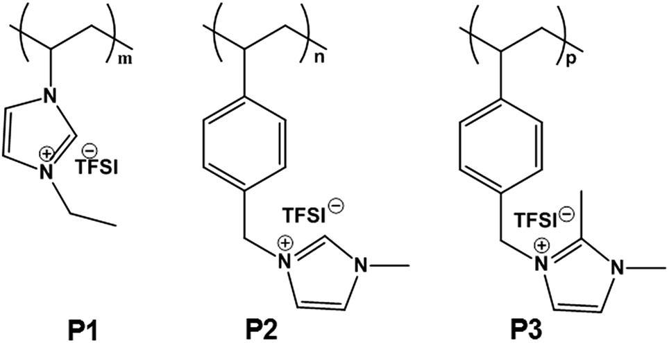 | ||
| Fig. 1 Chemical structures of three PIL binders used in this study. TFSI denotes the counter anion, bis(trifluoromethane sulfonyl)imide. | ||
The success in the monomer and PIL synthesis was confirmed by proton nuclear magnetic resonance (1H-NMR) spectra and Fourier transform infrared spectroscopy (FT-IR) in Fig. S1 and S2.† Gel permeation chromatography was performed to determine the number-average apparent molecular weight of the PILs, which are 130, 85 and 37 kDa, respectively (Fig. S3†). These PILs feature a high density of IL species, i.e. one per unit, as well as a multivalent binding power via the linear connection of the IL species into a polymer backbone. The polymers are expected to possess a broad electrochemical window and enhanced surface activity, two of the key requirements for binder materials. In the specific design of this work, 3 different PILs in terms of the backbone structure and substitution pattern on the imidazolium ring were chosen and are denoted as P1, P2, and P3, respectively. P1 has a polyvinylimidazolium-based backbone while P2 and P3 have a polystyrene-based one. Additionally, P2 and P3 differentiate in terms of blocking the alkalinity of the C2 position with a methyl unit.
The electrochemical properties of the PIL binders were investigated by several electrochemical techniques. First of all, we examined our binders using LiFePO4 as a model cathode material (a redox potential at 3.4 V vs. Li/Li+; a theoretical specific capacity of 170 mA h g−1) with a current density of 1C, which will assumes fully charge or discharge in one hour (=170 mA g−1).30–32 The charge–discharge curves show that PIL binders P1, P2 and P3 favorably delivered a higher specific capacity of 126, 132 and 137 mA h g−1, respectively, higher than the PVDF binder with 120 mA h g−1. This result indicates that PILs can make a higher specific capacity of the material accessible. In parallel, the electrodes with P1, P2 and P3 were proven stable until 100 cycles at the same current density (Fig. 2B).
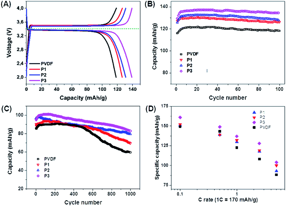 | ||
| Fig. 2 Electrochemical properties of LiFePO4 electrodes using different PIL binders. (A) Charge–discharge curves at a current density of 1C (=170 mA g−1). (B) Cycling performance up to 100 cycles at 1C. (C) Cycling performance up to 1000 cycles at 5C (=850 mA g−1). (D) Rate capability for PIL binders and PVDF. The rate capability data of PVDF (the black line in (A), (B) and (C)) was taken from ref. 29 (active materials loading 2.5 mg). | ||
Further investigations on the PIL binders were executed by a higher current density of 5C (=850 mA g−1), which is harsh and provides accelerated ageing of all involved materials (Fig. 2C). The cathodes using PVDF, P1, P2 and P3 show at these high currents initial discharge capacities of 85, 90, 96 and 101 mA h g−1, respectively. P1 exhibits the lowest specific capacity, while P3 presents both a highest specific capacity and the best cycling stability, with around 86% retention of the initial specific capacity after 1000 cycles (Fig. 3C). This is the highest value of the tested binders in this work. Also the rate capability suggests that P3 is the best structure among the three tested PIL binders (Fig. 3D).
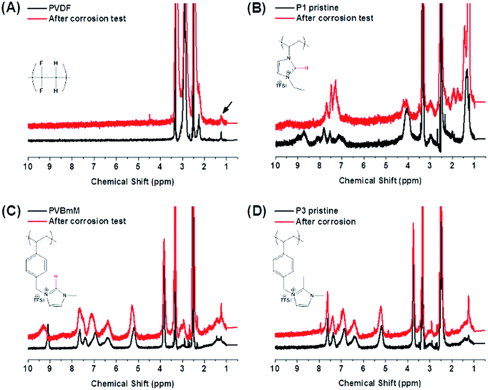 | ||
| Fig. 3 1H-NMR spectra of PVDF and 3 PIL binders to track changes of the chemical structure before and after the electrochemical corrosion test. (A) PVDF, (B) P1, (C) P2 and (D) P3. The black arrow in a point out a peak assigned to a grease residue involved in all samples. | ||
To track the chemical alterations being potentially responsible for the different behaviors of these binders in the electrode operation, 1H-NMR (Fig. 3) and FT-IR (Fig. S5†) spectroscopies were employed to analyze the chemical structure for all binders before and after a 2 week corrosion test at 4.0 V vs. Li/Li+ (see ESI† for details). In Fig. 3A, the 1H-NMR spectra of PVDF appear identical before and after the test, indicating that PVDF is inert during this well-define process. In comparison in Fig. 3B of P1, peaks between 7 and 9.5 ppm assigned to the imidazolium protons have changed significantly. The protic α-H (marked in red) at C2 position vanished after the test. It is known that the α-H due to its acidity may become invisible due to proton exchange with protic NMR solvents. In the current case, a non-protic NMR solvent, DMSO-d6 was used for these two samples under identical conditions, and the signal of α-H in P1 disappeared only in the sample after the corrosion test. This comparison thus supports unambiguously the occurrence of side reactions at the C2 position. Additionally, in the FT-IR spectrum of the P1 binder, the bands at 2950 cm−1 assigned to –CH3 stretching models (Fig. S5B†) disappeared completely at their original position and a set of new bands were observed at 3150 cm−1, implying that the α-H elimination may form the imidazol-2-ylidene persistent carbene under the electrochemical condition.33 Furthermore, the appearance of multiple peaks from 1600 to 1725 cm−1 in P1 after the corrosion test is indicative of the oxidation of the ethyl substituent into several types of carbonyl functions, such as aldehyde, ketone or carboxylic acids, which cannot be specifically distinguished at present. Bearing this observation in mind, we concluded that P1, though delivers a high specific capacity in the initial runs (Fig. 2B), is intrinsically unstable during the long term charging–recharging process. In the case of P2 (Fig. 3C), less changes were observed in the 1H-NMR spectra. The change in α-H signal was nevertheless spotted by a slight shift from 9.2 to 9.5 ppm, a sign that α-H elimination takes place only partially. Affected by this side reaction, the other 2 imidazolium protons deform their signals around 7.5 ppm. The two FTIR spectra did not present detectable variation before and after the corrosion tests. A close view on the chemical structures of P1 and P2 implies that the large phenyl ring attached to the imidazolium unit via a methylene bridge exerts a positive effect, which is possibly related to the sterical hindrance that minimizes the attack to the imidazolium ring. In the case of P3, the basic C2 position was blocked by a methyl group. No change was identified at all in both 1H-NMR and FTIR spectra (Fig. 3D and S5C and D†). P3 is intrinsically the most inert among the three PILs in a harsh electrochemical environment and maintains its glueing and conducting power.
Further investigations were carried out to explain the exact functions of PIL binders to deliver higher specific capacities than PVDF. In our previous report, the PIL nanoparticle binders were discussed to reduce the interfacial charge transfer resistance, being a major part of resistance in Li+ intercalation mechanism.29 In order to give a deeper insight in this phenomenon of the current linear PIL system, we build up the cathodes made of only binders (the cell configuration is PIL/liquid electrolyte/Li) and measured cyclic voltammograms (CVs) and electrochemical impedance spectra (EIS) at room temperature (Fig. 4). We applied an equivalent circuit based on half-blocking cell to fit the EIS which is constituted of an electrolyte resistance (Rs), charge transfer resistance (R1 and R2), constant phase element (CPE1 and CPE2), and capacitance at the blocking electrode (C1). For PVDF, P2, and P3, the CVs exhibited similar specific capacitance and showed no redox peak for all samples, which means that there is no electrochemical transition/energy storage function for the PIL binders (Fig. 4A). Only P1 shows small anodic peak suggesting formation of decomposition as shown by the 1H-NMR spectrum (Fig. 3B). However, the EIS show that the PIL binders are Li+ conductors in the presence of electrolyte (LiPF6 in EC/DMC) while PVDF is not (Fig. 4B and S6, and Table S1†). A high Li+ conductivity of PILs is found in general in the presence of Li salts, which was also well studied by Ohno and other researchers.23,34,35 The pristine PIL phase doesn't contain any Li+ and is not a Li+ conductor. The Li+ conductivity in the cell occurred after a formation of PIL/liquid electrolyte swollen layer phase, where the lithium salt starts to diffuse into the PIL phase and turns it into a Li+ conductor. Worth mentioning, the binder P3 outperforms all other systems already in this short term experiment, i.e. it provides the lowest ion and current flux resistance.
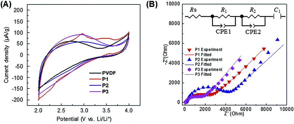 | ||
| Fig. 4 Electrochemical characterization for the PIL binders and PVDF. (A) Cyclic voltammograms, and (B) electrochemical impedance spectra at room temperature. | ||
Considering these results, we can propose an overall mechanism for high electrochemical performance where the PIL binders do not only glue the particles, but actively contribute to the high ion conductivity in a two-phase nano-heterojunction system.36,37 The PIL binders absorb the organic electrolyte in their chain structures, building up a nanometer thick layer with a higher concentration of Li+ at the interface to the active battery material (here LiFePO4) of PIL binder and bulk electrolyte (Fig. 5). It must be underlined that the build-up of an (inhibitive) Maxwell–Wagner polarization sensitively depends on the charge concentrations at the interface. The applied equivalent circuit model for the Li+-cathode containing two semi-circles to fit the experimentally obtained impedance signal (Fig. 4B inset): the first semi-circle is related to Li+ transfer resistance from a bulk liquid electrolyte to the heterophase associated with the desolvation process (R1), and the second semi-circle described the Li+ transfer resistance in the LiFePO4 heterophase (R2).38–40 From a view of chemistry, the data describe an enhanced electrochemical reactions via high ion conductivity and high electrochemical stability of an enriched electrolyte nanophase, as the concentration of Li+ in the PIL-stabilization layer is higher than in the bulk because the PILs are favorably polarized media.
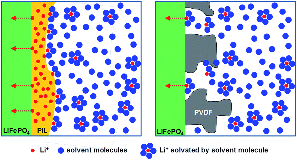 | ||
| Fig. 5 Hypothetic schematic illustration of effect on PIL/electrolyte heterophase for high Li+ conductivity (left). On the other hand, PVDF blocks the Li+ transport (right), therefore, it shows a higher resistance (=low Li+ flux) compared to the cathode composed with the PIL binders. For the simplification, carbon additives are not described in the figure. | ||
In the EIS measurements P3 showed both the lowest R1 and R2 among the three PILs (Fig. 4B and Table S1†). We can only speculate why P3 is most favourable, but it is to be assumed that the 3 solvophilic substituents on the charged imidazolium ring prohibit the known interface packing41 and thereby give the space to embed mobile Li-ions. From this point of view, PVDF is in any case an undesired choice, as it forms an insulation layer, independent of the presence of electrolyte (Fig. 5 and S6†).
Also for interaction with the conductive carbon additive, the formation of interfacial space Li+ charging layer will promote ionic character and conduction. The well-known charge transfer interaction between PILs to carbons making them perfect nanocarbon stabilizers42,43 is not only creating a favourable structural electron pathway due to a strong interaction between carbon and PILs, but at the same time will also increase the number of charge carriers by charge transfer effects.
4. Conclusions
In conclusion, our results, using a LiFePO4-cathode of a LIB as a model electrochemical system, show that already linear PIL binders following specific structure designs can significantly improve the electrochemical performance of even current daily systems. This could be related to improved charge transfer processes between solvent/salt and binder and binder/salt and active material, while the creation of a new inter-phase improves both the ion and electron conductions. To our opinion, the use of such functional binder with adopted mediator function is a new strategy to impact electrochemical heterophase reactions in general, tackling both a slightly higher capacity, but essentially a better rate behavior and longer lifetimes of the resulting overall systems. We believe that different choices of polymer moieties would give more stable binders in high voltage region in order to apply to cathode materials such as LiCoPO4.Acknowledgements
The authors would like to thank the Max-Planck Society (MAXNET Energy program) for the financial support, and M & T Olivine Co., Ltd for providing high-quality LiFePO4.References
- M. Armand and J. M. Tarascon, Nature, 2008, 451, 652–657 CrossRef CAS PubMed.
- J.-M. Tarascon, Philos. Trans. R. Soc., A, 2010, 368, 3227–3241 CrossRef PubMed.
- Y.-C. Lu, B. M. Gallant, D. G. Kwabi, J. R. Harding, R. R. Mitchell, M. S. Whittingham and Y. Shao-Horn, Energy Environ. Sci., 2013, 6, 750 CAS.
- N. Yabuuchi, K. Kubota, M. Dahbi and S. Komaba, Chem. Rev., 2014, 114, 11636 CrossRef CAS PubMed.
- M. Winter and R. J. Brodd, Chem. Rev., 2004, 104, 4245 CrossRef CAS PubMed.
- J. Li, R. B. Lewis and J. R. Dahn, Electrochem. Solid-State Lett., 2007, 10, A17 CrossRef CAS.
- I. Kovalenko, B. Zdyrko, A. Magasinski, B. Hertzberg, Z. Milicev, R. Burtovyy, I. Luzinov and G. Yushin, Science, 2011, 334, 75 CrossRef CAS PubMed.
- S. Komaba, Y. Matsuura, T. Ishikawa, N. Yabuuchi, W. Murata and S. Kuze, Electrochem. Commun., 2012, 21, 65 CrossRef CAS.
- C. V. Amanchukwu, J. R. Harding, Y. Shao-Horn and P. T. Hammond, Chem. Mater., 2014, 27, 550 CrossRef.
- S.-J. Park, H. Zhao, G. Ai, C. Wang, X. Song, N. Yuca, V. S. Battaglia, W. Yang and G. Liu, J. Am. Chem. Soc., 2015, 137, 2565 CrossRef CAS PubMed.
- M. Wu, X. Xiao, N. Vukmirovic, S. Xun, P. K. Das, X. Song, P. Olalde-Velasco, D. Wang, A. Z. Weber, L.-W. Wang, V. S. Battaglia, W. Yang and G. Liu, J. Am. Chem. Soc., 2013, 135, 12048 CrossRef CAS PubMed.
- S. S. Zhang and T. R. Jow, J. Power Sources, 2002, 109, 422–426 CrossRef CAS.
- IEA, World Energy Outlook, IEA, 2014 Search PubMed.
- J. Yuan and M. Antonietti, Polymer, 2011, 52, 1469–1482 CrossRef CAS.
- M. Armand, F. Endres, D. R. MacFarlane, H. Ohno and B. Scrosati, Nat. Mater., 2009, 8, 621 CrossRef CAS PubMed.
- G. Gebresilassie Eshetu, M. Armand, B. Scrosati and S. Passerini, Angew. Chem., Int. Ed., 2014, 53, 13342 CrossRef CAS PubMed.
- K. Sakaushi and M. Antonietti, Bull. Chem. Soc. Jpn., 2015, 88, 386 CrossRef CAS.
- K. Kishimoto, M. Yoshio, T. Mukai, M. Yoshizawa, H. Ohno and T. Kato, J. Am. Chem. Soc., 2003, 125, 3196 CrossRef CAS PubMed.
- J. Ranke, S. Stolte, R. Störmann, J. Arning and B. Jastorff, Chem. Rev., 2007, 107, 2183 CrossRef CAS PubMed.
- A. Fernicola, F. Croce, B. Scrosati, T. Watanabe and H. Ohno, J. Power Sources, 2007, 174, 342 CrossRef CAS.
- K. Sakaushi, T.-P. Fellinger and M. Antonietti, ChemSusChem, 2015, 8, 1156 CrossRef CAS PubMed.
- J. Yuan and M. Antonietti, Macromolecules, 2011, 44, 744–750 CrossRef CAS.
- H. Ohno, Electrochim. Acta, 2001, 46, 1407 CrossRef CAS.
- G. B. Appetecchi, G. T. Kim, M. Montanino, M. Carewska, R. Marcilla, D. Mecerreyes and I. de Meatza, J. Power Sources, 2010, 195, 3668 CrossRef CAS.
- H. Hu, W. Yuan, Z. Jia and G. L. Baker, RSC Adv., 2015, 5, 3135 RSC.
- H. Hu, W. Yuan, L. Lu, H. Zhao, Z. Jia and G. L. Baker, J. Polym. Sci., Part A: Polym. Chem., 2014, 52, 2104 CrossRef CAS.
- Z. Jia, W. Yuan, C. Sheng, H. Zhao, H. Hu and G. L. Baker, J. Polym. Sci., Part A: Polym. Chem., 2015, 53, 1339 CrossRef CAS.
- J. von Zamory, M. Bedu, S. Fantini, S. Passerini and E. Paillard, J. Power Sources, 2013, 240, 745 CrossRef CAS.
- J. Yuan, S. Prescher, K. Sakaushi and M. Antonietti, J. Mater. Chem. A, 2015, 3, 7229 CAS.
- A. K. Padhi, K. S. Nanjundaswamy and J. B. Goodenough, J. Electrochem. Soc., 1997, 144, 1188 CrossRef CAS.
- A. Yamada, S. C. Chung and K. Hinokuma, J. Electrochem. Soc., 2001, 148, A224 CrossRef CAS.
- Y. Wang, Y. Wang, E. Hosono, K. Wang and H. Zhou, Angew. Chem., Int. Ed., 2008, 47, 7461 CrossRef CAS PubMed.
- A. J. Arduengo, H. V. R. Dias, R. L. Harlow and M. Kline, J. Am. Chem. Soc., 1992, 114, 5530 CrossRef CAS.
- H. Sakaebe, H. Matsumoto and K. Tatsumi, J. Power Sources, 2005, 146, 693 CrossRef CAS.
- A. Fernicola, B. Scrosati and H. Ohno, Ionics, 2006, 12, 95 CrossRef CAS.
- J. Maier, Prog. Solid State Chem., 1995, 23, 171 CrossRef CAS.
- J. Maier, Nat. Mater., 2005, 4, 805 CrossRef CAS PubMed.
- P. G. Bruce and M. Y. Saidi, J. Electroanal. Chem., 1992, 332, 93 CrossRef.
- K. Sakaushi, G. Nickerl, F. M. Wisser, D. Nishio-Hamane, E. Hosono, H. S. Zhou, S. Kaskel and J. Eckert, Angew. Chem., Int. Ed., 2012, 51, 7850 CrossRef CAS PubMed.
- K. Sakaushi, E. Hosono, G. Nickerl, T. Gemming, H. S. Zhou, S. Kaskel and J. Eckert, Nat. Commun., 2013, 4, 1485 CrossRef PubMed.
- Y. Zhou and M. Antonietti, Chem. Mater., 2004, 16, 544 CrossRef CAS.
- D. Kuzmicz, S. Prescher, F. Polzer, S. Soll, C. Seitz, M. Antonietti and J. Yuan, Angew. Chem., Int. Ed., 2014, 53, 1062 CrossRef CAS PubMed.
- Y. Men, X.-H. Li, M. Antonietti and J. Yuan, Poly. Chem., 2012, 3, 871–873 RSC.
Footnotes |
| † Electronic supplementary information (ESI) available. See DOI: 10.1039/c5ra16535k |
| ‡ Present address: Chosun University, Department of Bio-chemical and polymer engineering, 309 Pilmun-daero, Dong-gu, Gwangju 501-759, Korea. |
| This journal is © The Royal Society of Chemistry 2015 |