
Direct electrochemical deposition of polyaniline nanowire array on reduced graphene oxide modified graphite electrode for direct electron transfer biocatalysis†
Lin Xia,
Jianfei Xia and
Zonghua Wang*
Collaborative Innovation Center for Marine Biomass Fibers, Materials and Textiles of Shandong Province, Shandong Sino-Japanese Center for Collaborative Research of Carbon Nanomaterials, College of Chemical Science and Engineering, Qingdao University, Qingdao, Shandong 266071, China. E-mail: wangzonghua@qdu.edu.cn
First published on 22nd October 2015
Abstract
A highly ordered polyaniline (PANI) nanowire array is produced via a one-step template-free electrochemical approach on reduced graphene oxide (RGO) modified graphite electrode (GE). Direct electron transfer (DET) between glucose oxidase (GOx) and the electrode is achieved by using the PANI nanowire array with the immobilization of GOx. The DET based biocatalysis application of the as fabricated GOx/PANI/RGO/GE electrode has been demonstrated. The as-fabricated glucose sensor exhibits a very rapid response time (<3 s), a linear response to glucose in the concentration range of 0.1–8.5 mM, a sensitivity of 12.3 μA mM−1 cm−2, a low detection limit of 0.7 μM and good anti-interference ability. The as assembled glucose biofuel cell which uses GOx/PANI/RGO/GE as a bioanode and an electrochemically controlled cathode shows a maximum power output of 115.4 μW cm−2.
Introduction
Since the original work of Clark and Lyons1 in 1962 that developed the first enzyme-based electrochemical oxygen electrode, extensive research has been done on the development of electrochemical glucose sensors.2,3 In addition to diabetes control, glucose sensors also offer great promise to meet the high demand for glucose monitoring, from food analysis to bioprocess control.4 For enzymes employed in glucose sensors, taking glucose oxidase (GOx) as an example, it does not directly transfer electrons to conventional electrodes because of a thick protein layer surrounding its flavin adenine dinucleotide (FAD) redox center, which introduces an intrinsic barrier to direct electron transfer. Generally, artificial (synthetic) electron transfer mediators are employed to shuttle electrons from the redox center of the enzyme to the surface of the electrode. However the presence of the mediator would limit the application of the glucose sensors in areas which require a contaminant-free environment or long-term continuous glucose monitoring. Alternatively, direct electron transfer will not only allow efficient transduction of enzymatic recognition of a target analyte, but also omit the need for a co-substrate to complete the catalytic cycle.5 Accordingly, different innovative strategies have been developed for establishing and tailoring the electrical contact between the redox center of GOx and electrode surfaces.5–7Recent development in nanomaterials has opened great opportunities for achieving direct electron transfer to enzymes for exploring glucose sensing applications.8 Various nanomaterials, such as carbon nanotubes,6 metal nanoparticles,9 metal oxides10 and nanostructured conducting polymers,11 have been utilized to fabricate high performance glucose sensors. Among various nanomaterials, conducting polymers have attracted much attention due to their unique and controllable chemical and electrical properties, bio-compatibility, and moreover a broad range of tunable properties emanating from their structural flexibility.12,13 PANI has been extensively studied due to its interesting electrochemical property,14 simple preparation and low cost.15 Recently, many attempts have been made on the preparation of nanostructured PANI16–18 and the exploration of their sensing application.19–22 From the evaluation of sensing performance achieved by different nanostructures, it is indicated that the surface/volume ratio of nanomaterials plays a key role in achieving better performance. Besides, the orderliness of the nanostructure also has significant influence on the according sensing performance due to their fast ion diffusion pathway. Therefore, vertically aligned PANI nanoarray composed of uniform small diameter PANI nanowires is promising for direct electron transfer based bio-catalysis applications.
Besides performance, low-cost fabrication of biosensors or biofuel cells (BFCs) is also important to their practical usage. Graphite is one of the cheapest supporting electrode materials that used for both biosensors and BFCs construction. The modification of graphite with conducting polymer nanostructures has been achieved by solution based23 or microwave-assisted chemical-vapor-induced24 in situ polymerization. However, compared with direct electrochemical deposition, these chemical methods are generally time-consuming and require additional oxidants. Recently, Cao et al. reported the electrodeposition of PANI nanorods on the surface of patterned RGO substrate for the supercapacitor application.25 Therefore, a facile approach to modify graphite electrodes with conducting polymer nanomaterials for highly efficient electrochemical bio-catalysis is still desirable.
In this work, highly ordered PANI nanowires array is prepared via a one-step template-free electrochemical approach on RGO modified GE (RGO/GE). DET between GOx and the electrode is achieved by using PANI nanowires array. The DET based biocatalysis application of the as fabricated GOx/PANI/RGO-GE electrode has been demonstrated.
Experimental
Reagents
Aniline (Aldrich) was distilled under reduced pressure prior to use. HClO4 (Sinopharm Chemical Reagent Co., China) was used as purchased without any further purification. GOx (E. C. 1.1.3.4, from Biozyme, UK, 265 units per mg), β-D-(+)-glucose (Sigma), ascorbic acid (AA), uric acid (UA) were used as received. All aqueous solutions were prepared in distilled water. Graphite electrode were purchased from XFNANO, China.Instruments
All the electrochemical experiments were performed by VMP3 potentiostat/galvanostat (EG & G, Princeton Applied Research). The morphologies of PANI nanowires array were investigated by Hitachi S-4800 field emission scanning electron microscope (FE-SEM).Preparation of RGO/GE electrode
Firstly, a 0.5 mg mL−1 GO solution was casted on polished graphite electrode and dried to form a thin GO film on the electrode, and then the GO/GE was electrochemically reduced to RGO/GE by applying a −1.0 V potential for 200 seconds.Preparation of PANI/RGO/GE electrode
PANI nanowires array was obtained by a galvanostatic current electrochemical approach modified from a previous reported method for electrochemical deposition of PANI nanowires array on platinum substrate.26 Typically, a RGO/GE (1 × 2 cm) was used as the working electrode, a Pt plate and saturated calomel electrode (SCE) were used as counter and reference electrodes. Electrolyte solution was composed of 0.1 M aniline and 1 M HClO4. Polymerization was carried out at a constant current, 0.01 mA cm−2, for 40 min. After polymerization, the working electrode was taken out from the electrolyte solution, washed with distilled water, ethanol, and ether respectively, and then dried in air for further characterization.Immobilization of enzyme on PANI nanostructures
Before the immobilization of GOx, the as-prepared PANI nanostructure was subjected to a reduction process in a phosphate buffer solution (PBS) (pH = 7.4), at a potential of −0.1 V maintained for 10–15 min, in order to remove the anions and other physically-adsorbed residues. Then the reduced PANI nanostructures was oxidized in PBS (pH = 7.4, containing 3 mg mL−1 of GOx) under a potential of +0.70 V for 15 min. The immobilization of GOx was achieved via electrostatic interaction between the positive-charged (oxidized) PANI nanowires surface and the negative-charged GOx molecules during the oxidation process.Biofuel cell construction
The assembled GOx/PANI/RGO/GE electrodes served as the anode in a single compartment electrochemical cell (10 mL); consisting of nitrogen saturated 0.1 M PBS buffer (pH 6.8) and glucose (30 mM). The cathode was potentiostatically controlled, using three-electrode configuration: graphite plate (6 × 10 mm) as working electrode, platinum wire as counter electrode and Ag/AgCl as a reference electrode (ALS, Tokyo, Japan). The cathode was biased at a potential of +500 mV against Ag/AgCl. The voltage generated from the biofuel cell was measured by a hand held multimeter (DM-97, Sinometer, China). Various external resistances were applied between the anode and cathode by a resistance decade box (RBOX 408, Lutron Electronic Enterprise, Taipei, Taiwan). The generated voltage at each resistance was measured after reaching equilibrium. Measurements were carried out at ambient temperature.Results and discussion
Characteristics of the RGO and PANI nanowires array modified graphite electrode
Fig. 1a displays a typical SEM image of electrochemically reduced GO thin film on GE surface. The thickness of the RGO film is less than 2 μm and composed of multi-layered graphene as shown in the inset of Fig. 1a. This pre-modification of RGO on the graphite electrode is essential to the subsequent electrochemical deposition of PANI nanowires array. RGO is more conductive than GO, while still maintaining oxygen-containing functional groups, which may be favourable for initialling PANI nucleation process for ordered nanowires array growth.27 An evidence of this speculation was show in Fig. 1d. When the electrochemical polymerization of PANI was carried out on the unmodified graphite surface, only PANI films composed of disordered nanowires network can be obtained and the nanowires polymerized here shows larger diameters. Another important factor for PANI nanowires array formation is the controlled current density. The influence of applied current density on the morphology of electrochemical polymerized PANI on RGO/GE was shown in Fig. S1.† With a given monomer aniline concentration, higher current density (from 0.02 to 0.08 mA cm−2) results PANI disordered nanowires network film formation, while a lower current density (0.006 mA cm−2) leads to the formation of thin PANI film with randomly distributed granular micro/nano structures.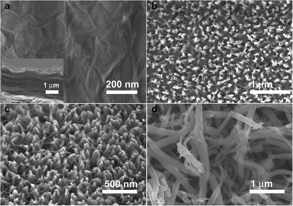 | ||
| Fig. 1 SEM image of (a) RGO modified graphite electrode, inset: cross section of the thin RGO film; (b) top view and (c) tilted view of the highly ordered PANI nanowire array electrochemically polymerized on RGO/GE; (d) disordered PANI nanowire electrochemically polymerized on graphite electrode. | ||
From the direct observation, the as-prepared PANI nanowires array showed a uniform green thin film covered on the RGO-GE electrode. For a detailed view from SEM images, the uniform white spots from the top view (Fig. 1b) were tips of PANI nanowires, which suggest the uniform distribution of nanowires. When the sample was tilted by 30° (Fig. 1c), the well-aligned PANI nanowires were clearly revealed, which were all oriented perpendicular to the substrate. The average diameter of PANI nanowires is about 50 nm, and the average length is about 300 nm measured from SEM images. Such a highly ordered uniform nanowires array is very desirable for sensing application. Firstly, the individual nanowire in this array possess smaller diameters compared with other works of nanostructured conducting polymers based glucose sensors,21,22,28 accordingly it can provide extremely large surface area for enzyme immobilization and analytical reactions. Secondly, it promotes the ion diffusion from a bulky solution to the surface of PANI nanowires. Moreover, as these nanowires are so short, the signal transduction associated with analytical reactions that occur within the nanowires array can be very efficient.
Direct electron transfer between GOx and PANI nanowires array
GOx is a flavoenzyme with a molecular weight of 150–180 kDa comprised of two identical tightly bound FAD cofactors. The electrochemical catalytic processes of GOx at the electrode surface can be depicted as followings:| GOx(FAD) + glucose → GOx(FADH2) + gluconolactone | (1) |
| GOx(FADH2) → GOx(FAD) + 2e− + 2H+ | (2) |
An illustration of the direct electron transfer between the GOx and the PANI nanowires array based electrode was given in Fig. 2a. The PANI nanowires served as the immobilization matrix and electron conductor wires at the same time.
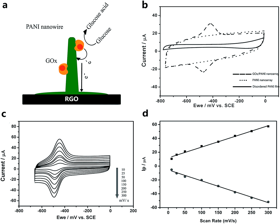 | ||
| Fig. 2 (a) An illustration of direct electron transfer between GOx and PANI nanowire; (b) cyclic voltammograms of PANI nanowires array (dotted line), GOx/PANI film composed of disordered PANI micro/nanowires (solid line), and GOx/PANI nanowires array (dash line) modified RGO/GE in PBS (0.1 M, pH 6.8) in the absence of glucose, scan rate 50 mV s−1. (c) Cyclic voltammograms at various scan rates from 10, 25, 50, 100, 150, 200, and 250 to 300 mV s−1, respectively. (d) Plot of peak current (Ip) vs. scan rate. | ||
The cyclic voltammograms (CV) of the PANI nanowire array with and without GOx, and PANI films composed of disordered PANI micro/nanowires were demonstrated in Fig. 2b, which are obtained in N2-saturated 0.1 M phosphate buffer solution (PBS, pH 6.8) in the absence of glucose. No redox peaks are observed at both the PANI nanowire array and GOx/PANI films on GE electrodes in the working range of glucose sensors (−750 mV to 0 mV). The CV curve of PANI nanowires array indicated that PANI nanowires cannot be oxidized in this potential range. The GOx/PANI/RGO/GE shows a pair of well-defined and nearly symmetrical redox peaks, with the anodic and cathodic peak potentials at −416 mV and −478 mV at 50 mV s−1, respectively.
The value of E0′ is −447 mV (at 50 mV s−1), which is consistent with other studies of direct electron transfer at pH 7.0 by using CNT-based electrodes6,29 or template-produced PANI nanowires modified electrodes.21 The well-defined symmetrical redox peaks suggest that the electrostatically immobilized GOx on the PANI nanowires array displays a quasi-reversible electrochemical reaction despite its complicate molecular structure.
Besides, CVs of GOx/PANI/RGO/GE recorded in nitrogen saturated 0.1 M phosphate buffer (pH 6.8) at a variety of scan rates are shown in Fig. 2c. As shown from the plot of peak current versus the scan rate in Fig. 2d, the peak current increased linearly with scan rate (up to 0.3 V s−1), which indicates that the redox process of GOx on this nanostructured electrode is a reversible and surface-confined process.
Electrochemical sensing of glucose
CV results of the catalytic performance of GOx/PANI/RGO/GE towards glucose oxidation under N2 saturated condition are shown in Fig. 3a. In the presence of 5 mM of glucose, the evolution of anodic bio-electrocatalytic current resulting from the enzymatic oxidation of glucose was clearly visible (curve a) compared to the CVs obtained without glucose (curve b). Fig. 3b shows the amperometric response of the GOx/PANI nanowire array electrode towards the successive addition of glucose under continuously stirring in 0.1 M PBS solution (pH 5.5) at an applied potential of −400 mV (optimized parameters). The anodic current value increased immediately after the addition of glucose and achieved 95% steady-state current within about 3 s. In contrast, the disordered PANI micro/nanowire network film based glucose sensor shows a response time of about 10 s, which is much longer than that of the PANI nanowires array based one. This fast response is firstly due to the direct electron transfer on the well-aligned PANI nanowires. Moreover, short PANI nanowires lead to short signal transport pathway, accordingly the amperometric signal is obviously enhanced compared to the disordered PANI micro/nanowire network film (curve b, at an applied potential of −100 mV, optimized potential). The plot of current density versus glucose concentration (Fig. 3c) depicted a linear relationship over the range from 0.1 to 8.5 mM (R = 0.9959), with a sensitivity of 12.3 μA mM−1 cm−2. The detection limit is tested to be about 0.7 μM, determined at a signal-to-noise ratio of 3. The Michaelis–Menten constant (Kmapp), which is an important parameter to reveal enzyme–substrate reaction kinetic (enzymatic affinity), was calculated to be 1.52 mM according to the Lineweaver–Burk equation.30 This value is much lower than the value of the dissolved GOx, which is 27.0 mM,31 and is in line with that reported in other nanomaterials based glucose sensors, e.g., 2.37 mM;21 4.6 mM;32 8.5 mM;33 7.3 mM (ref. 34) and 1.54 mM.35 The smaller Kmapp indicates that the GOx/PANI/RGO/GE has better enzymatic activity and higher affinity for the glucose substrate.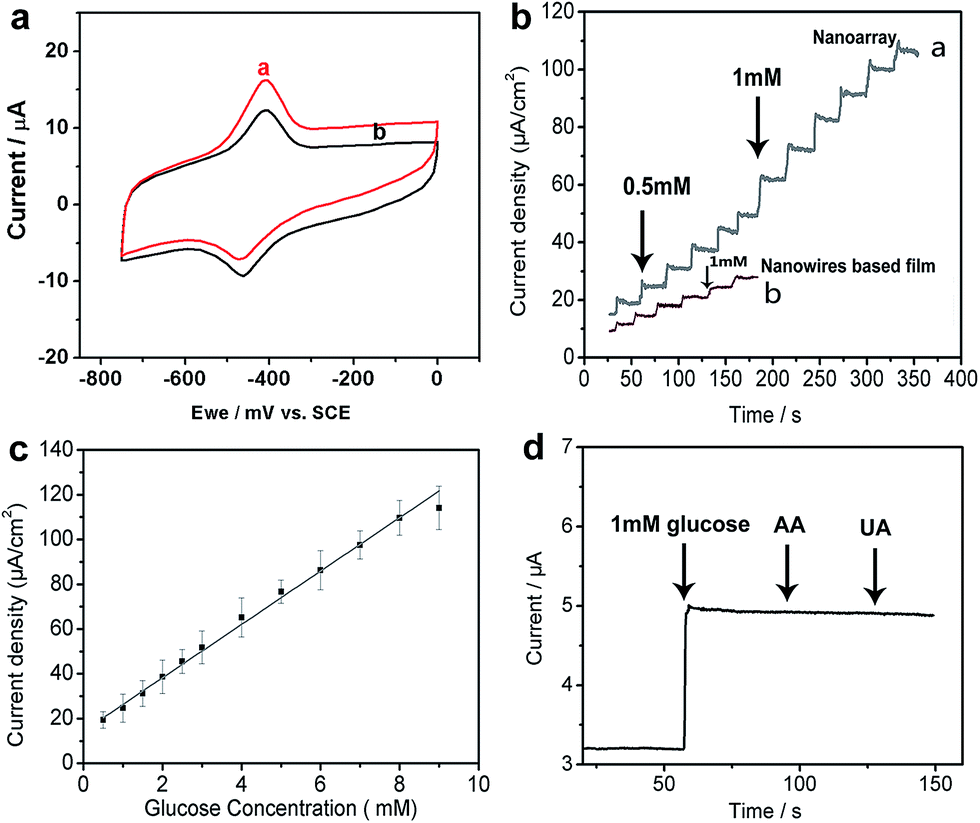 | ||
| Fig. 3 (a) 3 cyclic voltammograms of GOx/PANI/RGO/GE in the presence of 5 mM glucose (curve a) and absence of glucose (curve b), in 0.1 M, pH 6.8 PBS solution under N2 saturated condition, scan rate 10 mV s−1. (b) Amperometric response of the GOx/PANI/RGO/GE to successive addition of glucose in PBS (0.1 M, pH 5.5) at an applied potential of −400 mV, for disordered nanowires based film, the applied potential is −100 mV; (c) calibration curve for glucose obtained at the GOx/PANI/RGO/GE; (d) amperometric responses of the biosensor upon addition of glucose (1 mM), AA (0.2 mM) and UA (0.2 mM) in PBS, under an applied potential of −400 mV. | ||
A further comparison of GOx/PANI/RGO/GE electrode developed in this study with other GOx/nanomaterials based glucose sensor is shown in Table 1.
Interference study
For the potential application in real sample analysis, the anti-interference ability of the as-prepared biosensor is tested and shown in Fig. 3d. Compared with the obvious glucose response signal, signals of physiological level of AA and UA (0.2 mM, respectively) can be neglected. This superior anti-interference ability was attributed to the low operating potential that applied for the direct electron transfer detection of glucose, at which these interference species could not be oxidized.Storage stability of the biosensor
The storage stability of the glucose sensor is also of great importance for its practical usage. The current response of the as-prepared PANI nanowire array sensor towards 5 mM glucose along with time was shown in Fig. S3.† The sensor was stored at 4 °C in PBS buffer when not used. This as-prepared sensor exhibits good stability (about 90% for several repetitions during a week span and about 79% for over 25 days span), under the same detection-condition.Biofuel cell performance
Subsequently, BFCs were assembled based on GOx/PANI/RGO/GE anodes. The cathode was controlled by a potentiostat similarly to the way it was described by Schröder et al.,40 and was biased continuously at +500 mV vs. Ag/AgCl electrode. The fuel at the anode was glucose, and the fuel cell was of one compartment configuration and the PBS solution was bubbled with nitrogen. The performance of the biofuel cell with different anodes is shown in Fig. 4. Fig. 4a shows the power output measured from different modified bioanodes based BFCs. The GOx/PANI/RGO/GE anode based BFC shows a maximum power output of 115.4 μW cm−2 (curve a).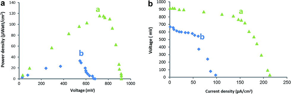 | ||
| Fig. 4 Power outputs (a) and polarization curves (b) of biofuel cells constructed with (a) GOx/PANI/RGO/GE anode, (b) disordered PANI nanowires covered graphite anode. Measurements were performed under N2 saturated PBS solution, in the presence of 30 mM glucose. A potential of +500 mV vs. Ag/AgCl was applied on the cathode. | ||
Because of the poor direct electron transfer ability of the disordered PANI micro/nanowires network films modified GE anode, 1 mM methylene blue was used as mediator when testing fuel cell performance. And a lower power output of 33.1 μW cm−2 (curve b) was measured. From the comparison of polarization curves shown in Fig. 4B, the BFCs with GOx/PANI/RGO/GE anodes demonstrated a polarization curve closer to rectangular shape, which is the ideal voltage–current relationship for an electrochemical generator of electricity. The fill factor (f) of the biofuel cell was ca. 59%, calculated according to eqn (3). Where Pmax is the maximum power output, Isc is the short-circuit current and Voc is the open circuit voltage.
| f = PmaxIsc−1Voc−1 | (3) |
This result indicates that this anode has an effective electrical contact and a reduced loss in mass transport.
Conclusions
In conclusion, we demonstrated a facile and low cost route to prepare ordered PANI nanowires array modified graphite electrodes and its capacity for direct electron transfer biocatalysis. Due to the highly ordered nanostructure of the PANI nanowires array and the achievement of the direct electron transfer from GOx to the electrode, the as fabricated biosensor shows rapid response time, low detection limit, practical linear range and good anti-interference ability. The biofuel cell assembled from the as-prepared anode shows a maximum power output of 115.4 μW cm−2.Acknowledgements
This work was supported by the National Science Foundation of China (21203228, 21275082, 21475071), the National Key Basic Research Development Program of China (973 special preliminary study plan, Grant No. 2012CB722705), the Taishan Scholar Program of Shandong Province.References
- L. C. Clark and C. Lyons, Ann. N. Y. Acad. Sci., 1962, 102, 29–45 CrossRef CAS PubMed.
- J. Wang, Chem. Rev., 2008, 108, 814–825 CrossRef CAS PubMed.
- J. Wang, Electroanalysis, 2001, 13, 983–988 CrossRef CAS.
- A. Heller and B. Feldman, Chem. Rev., 2008, 108, 2482–2505 CrossRef CAS PubMed.
- A. Heller, Acc. Chem. Res., 1990, 23, 128–134 CrossRef CAS.
- J. Q. Liu, A. Chou, W. Rahmat, M. N. Paddon-Row and J. J. Gooding, Electroanalysis, 2005, 17, 38–46 CrossRef CAS.
- M. Zayats, E. Katz and I. Willner, J. Am. Chem. Soc., 2002, 124, 2120–2121 CrossRef CAS PubMed.
- L. Xia, Z. X. Wei and M. X. Wan, J. Colloid Interface Sci., 2010, 341, 1–11 CrossRef CAS PubMed.
- S. Hrapovic, Y. L. Liu, K. B. Male and J. H. T. Luong, Anal. Chem., 2004, 76, 1083–1088 CrossRef CAS PubMed.
- X. W. Liu, Q. Y. Hu, Q. Wu, W. Zhang, Z. Fang and Q. B. Xie, Colloids Surf., B, 2009, 74, 154–158 CrossRef CAS PubMed.
- P. Santhosh, K. M. Manesh, S. Uthayakumar, A. I. Gopalan and K. P. Lee, Biosens. Bioelectron., 2009, 24, 2008–2014 CrossRef CAS PubMed.
- Handbook of Conducting Polymers, ed. T.A. Skotheim, R. L. Elsenbaumer and J. R. Reynolds, Marcel Dekker, 1998 Search PubMed.
- J. C. Chiang and A. G. Macdiarmid, Synth. Met., 1986, 13, 193–205 CrossRef CAS.
- E. T. Kang, K. G. Neoh and K. L. Tan, Prog. Polym. Sci., 1998, 23, 277–324 CrossRef CAS.
- A. Rudge, J. Davey, I. Raistrick, S. Gottesfeld and J. P. Ferraris, J. Power Sources, 1994, 47, 89–107 CrossRef CAS.
- H. Y. Ma, Y. Q. Luo, S. X. Yang, Y. W. Li, F. Cao and J. Gong, J. Phys. Chem. C, 2011, 115, 12048–12053 CAS.
- Y. Yan, R. Wang, X. H. Qiu and Z. X. Wei, J. Am. Chem. Soc., 2010, 132, 12006–12012 CrossRef CAS PubMed.
- N. L. Yang, J. Zhai, M. X. Wan, D. Wang and L. Jiang, Synth. Met., 2010, 160, 1617–1622 CrossRef CAS.
- C. Dhand, M. Das, M. Datta and B. D. Malhotra, Biosens. Bioelectron., 2011, 26, 2811–2821 CrossRef CAS PubMed.
- M. Zhao, X. M. Wu and C. X. Cai, J. Phys. Chem. C, 2009, 113, 4987–4996 CAS.
- Z. Y. Wang, S. N. Liu, P. Wu and C. X. Cai, Anal. Chem., 2009, 81, 1638–1645 CrossRef CAS PubMed.
- Y. Y. Horng, Y. K. Hsu, A. Ganguly, C. C. Chen, L. C. Chen and K. H. Chen, Electrochem. Commun., 2009, 11, 850–853 CrossRef CAS.
- Y. Li, X. Zhao, P. Yu and Q. Zhang, Langmuir, 2013, 29, 493–500 CrossRef CAS PubMed.
- X. Li, L. Yang, Y. Lei, L. Gu and D. Xiao, ACS Appl. Mater. Interfaces, 2014, 6, 19978–19989 CAS.
- M. Xue, F. Li, J. Zhu, H. Song, M. Zhang and T. Cao, Adv. Funct. Mater., 2012, 22, 1284–1290 CrossRef CAS.
- K. Wang, J. Y. Huang and Z. X. Wei, J. Phys. Chem. C, 2010, 114, 8062–8067 CAS.
- N. A. Kumar, H.-J. Choi, Y. R. Shin, D. W. Chang, L. Dai and J.-B. Baek, ACS Nano, 2012, 6, 1715–1723 CrossRef CAS PubMed.
- Y. G. Liu, X. M. Feng, J. M. Shen, J. J. Zhu and W. H. Hou, J. Phys. Chem. B, 2008, 112, 9237–9242 CrossRef CAS PubMed.
- B. C. Janegitz, R. Pauliukaite, M. E. Ghica, C. M. A. Brett and O. Fatibello, Sens. Actuators, B, 2011, 158, 411–417 CrossRef CAS.
- R. A. Kamin and G. S. Wilson, Anal. Chem., 1980, 52, 1198–1205 CrossRef CAS.
- M. J. Rogers and K. G. Brandt, Biochemistry, 1971, 10, 4624–4630 CrossRef CAS PubMed.
- P. Du, B. Zhou and C. Cai, J. Electroanal. Chem., 2008, 614, 149–156 CrossRef CAS.
- X. Liu, L. Shi, W. Niu, H. Li and G. Xu, Biosens. Bioelectron., 2008, 23, 1887–1890 CrossRef CAS PubMed.
- B. A. Gregg and A. Heller, Anal. Chem., 1990, 62, 258–263 CrossRef CAS PubMed.
- P. Si, S. Ding, J. Yuan, X. W. Lou and D.-H. Kim, ACS Nano, 2011, 5, 7617–7626 CrossRef CAS PubMed.
- H. Zhang, Z. Meng, Q. Wang and J. Zheng, Sens. Actuators, B, 2011, 158, 23–27 CrossRef CAS.
- F. Li, J. Song, F. Li, X. Wang, Q. Zhang, D. Han, A. Ivaska and L. Niu, Biosens. Bioelectron., 2009, 25, 883–888 CrossRef CAS PubMed.
- C. Deng, J. Chen, X. Chen, C. Xiao, L. Nie and S. Yao, Biosens. Bioelectron., 2008, 23, 1272–1277 CrossRef CAS PubMed.
- X. Kang, J. Wang, H. Wu, I. A. Aksay, J. Liu and Y. Lin, Biosens. Bioelectron., 2009, 25, 901–905 CrossRef CAS PubMed.
- U. Schröder, J. Nießen and F. Scholz, Angew. Chem., Int. Ed., 2003, 42, 2880–2883 CrossRef PubMed.
Footnote |
| † Electronic supplementary information (ESI) available. See DOI: 10.1039/c5ra16365j |
| This journal is © The Royal Society of Chemistry 2015 |