
 Open Access Article
 This Open Access Article is licensed under a
 Creative Commons Attribution 3.0 Unported Licence
Electrostatic template-assisted deposition of microparticles on electrospun nanofibers: towards microstructured functional biochips for screening applications†
S.
Nedjari
a,
A.
Hébraud
a,
S.
Eap
b,
S.
Siegwald
a,
C.
Mélart
a,
N.
Benkirane-Jessel
b and
G.
Schlatter
*a
aICPEES Institut de Chimie et Procédés pour l'Energie, l'Environnement et la Santé, UMR 7515, CNRS, Université de Strasbourg, 25 Rue Becquerel, 67089 Strasbourg Cedex, France. E-mail: guy.schlatter@unistra.fr
bINSERM Unité 1109, Université de Strasbourg, 11 Rue Humann, F-67085 Strasbourg Cedex, France
First published on 28th September 2015
Abstract
Electrostatic Template-Assisted Deposition (ETAD) of microparticles is described as a new process to control the deposition of microparticles by electrospraying onto a substrate. It relies on the construction of an electrostatic template by electrospinning a thin layer of fibers onto a micropatterned collector. Because the fibers cannot release their charges when they are suspended over cavities of the micropatterned collector, an electrostatic template is formed with repulsive and attractive domains. This electrostatic template is then used to guide precisely the particle deposition during the electrospraying step. Microstructured bi-layer composites with a great variety of micropatterns can thus be elaborated with any kind of materials allowing the use of the ETAD process for a wide range of applications. As a proof of concept, the ETAD process was applied for the production of composite scaffolds with poly(ε-caprolactone) nanofibers covered by a micropatterned layer of hydroxyapatite. This scaffold was then embedded in a biochip containing 21 wells and used for MG-63 cell proliferation and mineralization studies, showing their possible application in the screening of the scaffold structure for tissue engineering.
1. Introduction
One of the main goals in cell biology is to find the optimal in vitro micro-environment to accurately mimic the in vivo one. Indeed, cell behaviors such as proliferation, migration and differentiation deeply depend on their micro-environment, which is defined by different parameters such as the topography, chemistry and stiffness of the substrate and the composition and physiochemical conditions (temperature, pH, O2, CO2) of the cell culture medium.1,2 Among these parameters, the substrate topography is identified as one of the most important impacting the cell fate, especially for stem or bone cells. High throughput screening has been developed in order to test a large number of micro-environment conditions and thus, find the best topography regarding the intended application. Thanks to microfabrication and microfluidics techniques, biochips (i.e. lab on chip devices devoted to biology) have emerged, offering the possibility to test different libraries of molecules or topographies in order to find the best cellular micro-environment.2 Furthermore, the high level of repeatability and rapidity provided by the biochips make them very attractive for biologists.3 Regarding the topography, biochips allow the screening of hundreds different patterns.4–7 However, because most of biochips are fabricated by photolithography, etching, or molding techniques, their topography cannot mimic satisfactorily the in vivo extracellular matrix (ECM), which is a nanofibrous composite. Therefore, screening a large number of fibrous structures should be promising, especially to find the adequate structure of fibrous scaffolds for tissue engineering, depending on the targeted application.A simple fabrication technique for the elaboration of submicronic fibrous scaffolds for tissue engineering is electrospinning. Indeed, electrospun scaffolds have proven to be excellent candidates as substrates for in vivo and in vitro cell growth.8 Moreover, using this technique, fibers can be easily organized in the form of 2D9–11 or 3D12–15 microstructured scaffolds, with tailored pore sizes to allow cell colonization and infiltration.16,17 Finally, it has been demonstrated that the topography of the electrospun scaffold has got an important influence on the cell behavior.18–20
Electrospun membranes have been incorporated in biochips allowing biological experimentations in individual micro-wells having a bottom with non-structured randomly deposited nanofibers.21–23 However, to the best of our knowledge, nobody reported the elaboration of biochips allowing cell culture for a wide range of micropatterned nanofibrous structures. In this work, we developed a new process, the Electrostatic Template-Assisted Deposition (ETAD), which allows the precise spatial deposition of microparticles onto electrospun nanofibers. From this process, we elaborated microstructured biochips to screen the topography of nanofibrous scaffolds for bone tissue engineering. For such application, several groups have shown that the addition of hydroxyapatite, the major mineral component of bone, to the nanofibrous scaffolds enhance the osteophilic environment for the growth and mineralization of osteoblasts.24–26 We thus elaborated a biochip for which the bottom of each well has its own composite fibrous microstructure (bars, hexagons, blocks or mazes) made of a layer of electrospun poly(ε-caprolactone) (PCL) fibers and a layer of electrosprayed hydroxyapatite (HA) microparticles. ETAD process allowed the precise location of the HA particles onto the PCL nanofibrous layer. MG-63 osteoblast-like cells were then cultured followed by immunochemistry and alizarin red staining to evaluate the influence of the micropatterned structures on the mineralization and to demonstrate the potential of application of such biochips.
2. Experimental section
2.1. Electrospinning/electrospraying
A vertical homemade electrospinning set-up was composed by a 18G needle connected to a positive high voltage power supply (Spellmann SL 10) and a rotative collector (rotating in the horizontal plan with a speed of 100 rpm) connected to the ground (high voltage power supply Spellmann SL 10). The polymer solution was pushed through the needle via a silicon feedline connected to a 10 mL syringe installed on a syringe pump.PCL polymer solutions were prepared 24 h before by dissolving poly(ε-caprolactone) (PCL) (Mw = 80 kg mol−1, PDI = 1.1, Perstrop, commercial name: CAPA 6806) into dichloromethane (DCM, Sigma-Aldrich)/N,N-dimethylformamide (DMF, ReagentPlus® ≥99%, Sigma-Aldrich) (60/40 v/v) at a concentration of 15 wt%. A 6 wt% hydroxyapatite (HA, Sigma-Aldrich, nanopowder with particles size ≤200 nm (BET), ≥97% synthetic) suspension was prepared in ethanol (Sigma-Aldrich) 48 h prior to electrospraying and ultrasonicated for 30 min (Branson Sonifier) just before processing.
In a first step, the PCL solution is electrospun during a time te (needle-to-collector distance = 13.5 cm, flow rate = 1 mL h−1, Vneedle = 25 kV). Then, in a second step, the HA suspension is electrosprayed over the layer of PCL nanofibers during 15 min (distance = 13.5 cm, flow rate = 0.62 mL h−1, Vneedle = 18 kV).
2.2. Fabrication of the biochip collector
The biochip micropatterned collectors were elaborated by using photolithographic processes onto silicon wafers, with a photoresist (SU-8 2050, MicroChem) and a mask aligner (MJB4, SUSS MicroTec). Electron beam evaporator Plassys MEB5505 was then used to deposit a conductive layer (Al-160 nm and Au-40 nm) on the collectors to make them conductive.On each biochip collector, 21 wells were fabricated with 21 different structures. Each well had a diameter of 5 mm and they were spaced from each other by 5 mm. 5 different kinds of structures were studied: hexagon, bar, block, maze and random structure. The characteristic sizes Ltop and Lbot are defined and summarized for each structure (see Fig. 2 and Table 1).
| Structure | Name | Controlled electrospraying for te = 90 s | Controlled electrospraying for te = 13 min | Width LHA of HA patterns for te = 13 min (μm) | % of surface area covered by HA for te = 90 s | S HA = % of surface area covered by HA for te = 13 min |
|---|---|---|---|---|---|---|
| Bar | Bar20,20 | Yes | No | — | 50 ± 3 | — |
| Bar80,20 | Yes | No | — | 80 ± 4 | — | |
| Bar20,60 | Yes | Yes | 18 ± 4 | 25 ± 2 | 23 ± 7 | |
| Bar80,60 | Yes | Yes | 18 ± 5 | 57 ± 3 | 23 ± 7 | |
| Bar20,80 | Yes | Yes | 15 ± 3 | 20 ± 2 | 16 ± 5 | |
| Bar80,80 | Yes | No | — | 50 ± 3 | — | |
| Block | Block60,80 | Yes | Yes | 17 ± 3 | 14 ± 2 | 23 ± 7 |
| Block120,80 | Yes | Yes | 17 ± 4 | 28 ± 2 | 16 ± 5 | |
| Block60,40 | Yes | No | — | 28 ± 2 | — | |
| Block120,40 | Yes | Yes | 16 ± 2 | 44 ± 3 | 19 ± 6 | |
| Hexagon | Hex20,240 | Yes | Yes | 19 ± 3 | 17 ± 2 | 16 ± 5 |
| Hex20,120 | Yes | Yes | 18 ± 3 | 30 ± 2 | 27 ± 9 | |
| Hex20,60 | Yes | Yes | 17 ± 3 | 48 ± 3 | 42 ± 12 | |
| Hex60,240 | Yes | Yes | 16 ± 3 | 40 ± 3 | 12 ± 3 | |
| Hex60,120 | Yes | Yes | 17 ± 2 | 60 ± 3 | 20 ± 6 | |
| Hex60,60 | Yes | No | — | 78 ± 4 | — | |
| Hex100,240 | Yes | Yes | 18 ± 2 | 54 ± 3 | 11 ± 3 | |
| Hex100,120 | Yes | Yes | 17 ± 3 | 74 ± 4 | 16 ± 5 | |
| Hex100,60 | Yes | No | — | 88 ± 4 | — | |
| Maze | Maze20,80 | Yes | Yes | 15 ± 3 | 20 ± 2 | 14 ± 5 |
| Flat | Random | Yes, random deposition | Yes | HA covers all the surface | 95 ± 5 | 85 ± 10 |
2.3. Fabrication of the biochip
The biochip was a homemade device (see Fig. 4b). It was composed of different elements:- A 50 × 50 mm PMMA plate drilled with 21 holes to form the wells, corresponding to the 21 different electrospun structures.
- A 50 × 50 mm PDMS seal with a height of 4 mm with 21 holes corresponding to the ones of the PMMA plate.
- A PCL/HA membrane obtained with the biochip collector.
- A 50 × 50 mm PMMA plate with a height of 5 mm.
Before assembling, each element of the biochip was sterilized in ethanol (except the PCL/HA membrane). The four elements were assembled together with four screws (see Fig. 4b). The assembled biochip was then exposed to UV light during 30 minutes to insure good sterilization. The PDMS seal was homemade. A 10/1 (wt/wt) mixture of PDMS-Sylgard Silicone Elastomer and Sylgard Curing Agent 184 (Dow Corning Corp., Seneffe, Belgique) was poured into a Petri dish.
Then, the mixture of PDMS-elastomer and curing agent was cured at 65 °C during 1 hour until the polymer became rigid. After cooling at room temperature, the PDMS seal was carefully peeled from the Petri dish and perforated with a punch to make 21 holes with a diameter of 5 mm.
2.4. SEM characterization
The morphology of the biochips collectors and membranes were observed by scanning electron microscopy (SEM) (VEGA 3 LMV, TESCAN, Czech Republic) with a voltage of 5 kV. Before observation, the samples were sputter-coated with gold using a Q 150RS sputter coater (Quorum Technologies Ltd, United Kingdom).2.5. Raman confocal microspectroscopy
The Raman confocal microscopy mapping were obtained using a Raman spectrometer (LabRam HR by Horiba Jobin-Yvon with a 600 lines per mm grating) coupled to a microscope (Model BX41, Olympus) with xyz mapping stage via optical fibers. The excitation of Raman scattering was operated with a green laser at a wave length of 532 nm. The laser beam was focused using the macro-mapping mode with a laser spot of 8 × 8 μm, steps of 8 μm and with a 10× microscope lens. A confocal pinhole of 200 μm diameter was placed before the entrance slit to reject the Raman signal from out-of-focus planes. For each spot, a Raman spectrum with a good signal-to-noise ratio was recorded with an integration time of 6 s. The peak at 1106–1131 cm−1 was attributed to PCL whereas the peak at 947–988 cm−1 was attributed to HA signal.2.6. Cell culture and seeding
Human osteoblast cells were obtained from the cell line MG-63 coming from human osteosarcosis. MG-63 osteoblasts were cultured in DMEM® (BioWhittaker® Lonza, France) completed with 10% FBS (Gibco® Life Technologies™, France), 50 U mL−1 penicillin, 50 μg mL−1 streptomycin, 2.5 μg mL−1 amphotericin B (BioWhittaker® Lonza, France), 200 mM sodium pyruvate (Gibco® Life technologies™, France), and 200 mM of glutamine (PAA, France) in 75 cm2 flasks. The cells were incubated at 37 °C in a humidified atmosphere of 5% CO2 and fed every 3 days. When cells reached sub-confluence, they were harvested by trypsin–EDTA treatment and viable cells were counted by trypan blue assay. The MG-63 osteoblasts were then seeded into the biochip 21-well plate at a density of 3000 cells per well and cultured with DMEM®. The seeded biochip were incubated at 37 °C in a humidified atmosphere of 5% CO2 and fed every 3 days. Biochips seeded with MG-63 osteoblasts were cultivated for 21 days in Dulbecco's modified eagle medium (D-MEM®, PAA, Austria) supplemented with 10% fetal bovine serum (FBS), 50 U mL−1 penicillin, 50 μg mL−1 streptomycin, 5 μg mL−1 Fungizone and 1% sodium pyruvate.2.7. Immunocytochemistry staining and observation
MG-63 osteoblasts cells were fixed with 4% paraformaldehyde for 1 h at 37 °C, permeabilized and saturated with a solution of 0.1% Triton X-100 and 1% BSA diluted in PBS for 1 h. After washing with PBS, the biochips were then incubated for 30 min with Alexa Fluor 546-conjugated phalloidin (1/200, Molecular Probes) for F-actin labelling and 5 min with 200 nM DAPI (Sigma) for nuclear staining. Bone growth induction and extracellular matrix synthesis were measured by assaying expression of osteocalcin using polyclonal goat anti-osteocalcin (1/200; Santa Cruz Biotechnology) overnight at 4 °C. After washing with PBS three times for 10 min, the seeded biochips were incubated with secondary anti-goat antibodies conjugated to Alexa Fluor 488 (1/200, Invitrogen). The biochips were observed under an epifluorescence microscope (LEICA DM 4000 B). Image treatment was carried out with Image J software. The exposition gain was 3 for the DAPI and osteocalcin images. The exposition time for DAPI was 350 milliseconds and the exposition time for osteocalcin was 920 milliseconds. Osteocalcin expression was observed after 21 days of cell culture in one biochip device.2.8. Observation of the cell morphology by SEM
After 3 days of culture, cells were fixed using 2.5% glutaraldehyde diluted in phosphate buffered saline (PBS) and then 1% osmium tetroxide diluted in PBS. The samples were then washed several times with PBS and dehydrated gradually with increasing concentrations of ethanol (25%, 50%, 75%, 90%, and 100%). Finally, the cells were chemically dehydrated with hexamethyldisilazane (HMDS) and observed by SEM as previously described.2.9. In vitro examination of mineralization using Alizarin red S staining after 21 days of cell culture
Alizarin red S powder was dissolved in distilled water at 2 g for 100 mL. The pH of the Alizarin red S solution was adjusted between 4.1 and 4.3. After washing the scaffolds with PBS twice, the cells were fixed by adding 75% ethanol in each well of the biochips. The biochips were incubated in the Alizarin red solution for 20 min and then thoroughly rinsed with distilled water. The biochips were then observed under an optical microscope. Image treatment was carried out with Image J software. Three biochips were incubated with the Alizarin red solution: two biochips seeded with MG-63 cells and one biochip without cells (as a negative control).3. Results and discussion
3.1. Electrostatic template-assisted deposition (ETAD)
It has been shown that when electrospinning is carried out on a collector having protuberances, the suspended portions of non-conducting fibers (i.e. which are not in contact with the collector) cannot efficiently release their electric charges27 whereas the fiber portions which are in direct contact with the collector can dissipate the charges. Thus, when using a micropatterned collector with walls and cavities, an electrostatic template showing both repulsive and attractive areas is formed (see Fig. 1a–c). Such electrostatic template has been used to control the deposition of the up-coming electrospun jet and produce 2D11,20 or even 3D13,14 patterned scaffolds. Thus, thanks to this electrostatic template effect, it was possible to control very precisely the deposition of electrosprayed hydroxyapatite (HA) microparticles. Indeed bi-layer composite membranes with a layer of PCL electrospun fibers covered by a structured layer of electrosprayed hydroxyapatite (HA) microparticles could be elaborated (see Fig. 1d–f). HA microparticles were selectively deposited on the walls of the patterns (i.e. where the PCL fiber portions were in direct contact with the collector). This highly selective deposition was observed for honeycomb patterns with an internal diameter as low as 40 μm (Fig. 1e). On the contrary, when the patterned collector was not previously covered by a layer of electrospun nanofibers, HA electrosprayed microparticles were deposited both on the pattern walls and in the pattern cavities (see Fig. 1g). This experiment proves without any doubt, that the electrostatic template-assisted deposition (ETAD) of electrosprayed particles is induced by the layer of fibers, which is firstly deposited on the patterned collector. Thus, the ETAD process allows the precise spatial deposition of microparticles onto a thin layer of nanofibers previously electrospun onto a microstructured collector.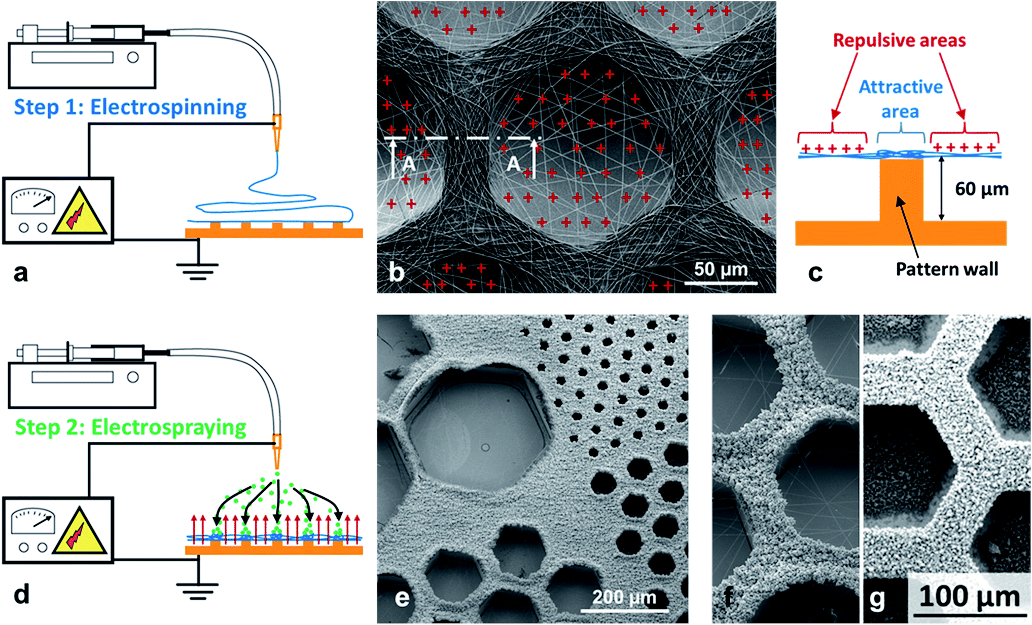 | ||
| Fig. 1 Principle of the electrostatic template-assisted deposition of electrosprayed microparticles on electrospun nanofibers. (a) Step 1 of the process: electrospinning on a micropatterned collector. (b) SEM picture showing electrospun PCL fibers deposited on a honeycomb pattern, the suspended fiber portions are positively charged. (c) Cross-section A–A of a pattern wall showing the repulsive suspended electrospun fibers and the attractive area located above the wall. (d) Step 2 of the process: electrospraying on the electrostatic template formed by the thin layer of fibers. (e) HA electrosprayed particles on a thin layer of PCL fibers obtained after only te = 45 s of electrospinning, a highly selective deposition is observed over honeycomb patterns with a wall width of Ltop = 20 μm an internal diameter ranging from Lbot = 40 to 360 μm (see Fig. 2c for the definition of Ltop and Lbot). (f) Detail of the previous picture for honeycomb patterns of internal diameter of 160 μm. (g) HA electrosprayed particles on a patterned collector without the presence of the layer of electrospun fibers: no selective deposition is observed. | ||
Using the ETAD process, it was possible to produce microstructured composite membranes of a large variety of pattern shapes such as bars, hexagons, blocks or maze (see Fig. 2a–j and Table 1). HA microparticles were precisely deposited on the top of the 21 different patterns of the collector in the case of the presence of a previously deposited thin layer of electrospun PCL fibers obtained for an electrospinning time te = 90 s (Fig. 2f–j). When the time te is increased to 13 min (corresponding to an average thickness of the PCL fibrous layer of roughly 80–150 μm), the controlled deposition is still observed but with some differences compared to shorter time te (see Fig. 2f′–j′). Indeed, by increasing te, the shape of the electrostatic template may change due to fiber aggregation or partial loss of the electric contact between the fibers and the top of the patterns. Thus, a first consequence of the increase of te was that whatever the pattern size Ltop, ranging from 20 to 120 μm (see Fig. 2b–e and Table 1), the corresponding width LHA of the patterns formed by the deposited HA microparticles was almost constant and ranged between 15 and 20 μm (see Table 1). Therefore, the percentage of surface area covered by the HA microparticles (SHA) was reduced when electrospraying after longer electrospinning times. While it was highly dependent on the structures of the patterns at short electrospinning times, ranging from 15 to 90% of the total surface, it became more uniform after longer times and around 15 to 30% for most of the patterns (Table 1). Regarding the bar and hexagonal patterns, HA particles were located exactly on the top of the patterns for the thinnest ones having an Ltop of 20 μm, with a low HA surface coverage of 16–20%, not really depending on te (see Fig. 2f′, 2g′ and 3). However, for patterns with larger width Ltop, the electric contact couldn't be insured over all the top surface of the patterns leading to bad electric charge release and thus the formation of repulsive areas. For such large Ltop, the contact was generally insured at the edges of the patterns leading to HA deposition only on these edges. As an example, in the case of Hex100,120, after te = 13 min of electrospinning, HA was only deposited on the edges of the patterns with SHA = 16 ± 5% (Fig. 2h′) whereas after a shorter electrospinning time, HA covered all the width Ltop of the patterns leading to SHA values as high as 74 ± 4% (see Fig. 2h). In the case of block patterns, whereas well-defined HA islands were formed at short te (SHA = 28 ± 2%, Fig. 2i), HA grids with a pitch corresponding to the distance between the centers of the blocks were observed after the longest electrospinning time te = 13 min (SHA = 16 ± 5%, Fig. 2i′). This phenomenon could be explained by the propensity of the PCL fibers to self-assemble after long times of electrospinning12 leading to the formation of bundles of fibers crossing the block gap. Indeed, such bundles, containing small amount of remaining solvent, allow the electric charges dissipation along their axes favoring thus their coverage by HA electrosprayed microparticles resulting in the formation of HA grids.
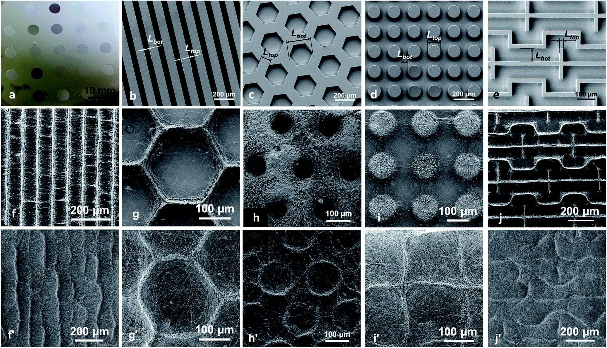 | ||
| Fig. 2 Effect of the thickness of the deposited layer of PCL nanofibers on the final HA deposition. (a) A collector with 21 micropatterned areas elaborated from photolithographic processes and definition of Ltop and Lbot. (b) Bar80,60 structures. (c) Hex100,240 structures. (d) Block120,80 structures. (e) Maze20,80 structures. PCL–HA bi-layers obtained after a time te of PCL electrospinning followed by 15 min of HA electrospraying (f–j) te = 90 s. (f′–j′) te = 13 min. (f and f′) Bar20,80. (g and g′) Hex20,240; (h and h′) Hex100,120. (i and i′) Block120,80. (j and j′) Maze20,80. | ||
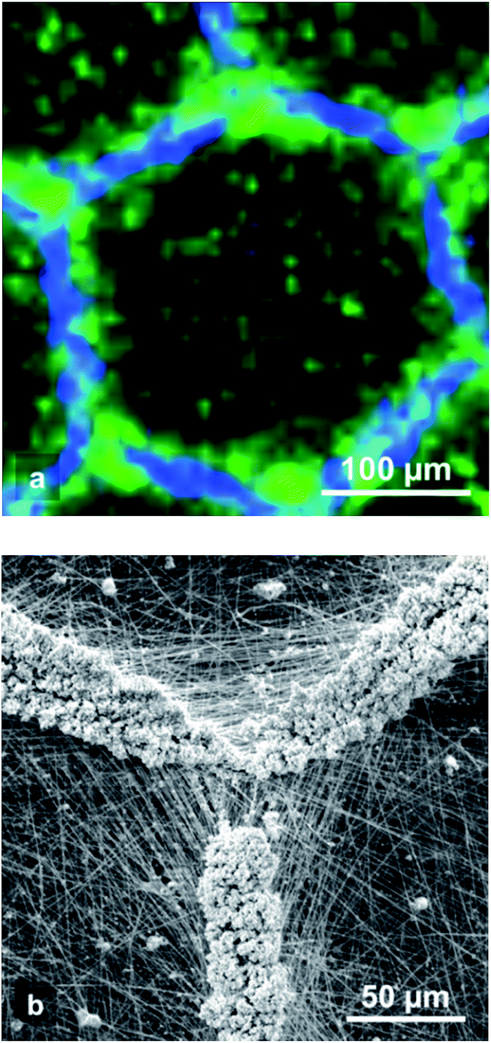 | ||
| Fig. 3 Hex20,240 PCL–HA bi-layer honeycomb patterns obtained after a time te = 13 min of PCL electrospinning followed by 15 min of HA electrospraying. (a) Chemical pattern obtained by Raman confocal microscopy showing HA in blue and PCL fibres in green. (b) Detail showing the HA nanoparticles deposited over the pattern walls at the crossing area of 3 honeycomb patterns. | ||
3.2. Biochips for the screening of composite microstructured materials for bone regeneration
Our goal is to demonstrate that the ETAD process can be applied for the elaboration of microstructured functional membranes, which are then implemented in a biochip to study the influence of the microstructuration on the behavior of MG-63 osteoblast-like cells. Membranes made of a layer of electrospun PCL nanofibers covered by a layer of electrosprayed hydroxyapatite microparticles were fabricated using the collector with 21 different micropatterned areas (Fig. 2a and Table 1). Each area of 5 mm in diameter corresponds to the position of a milli-culture well of the biochip. An electrospinning time te of 13 min was chosen in order to be able to peel off the membrane from the collector and to manipulate it, giving a final bi-layer scaffold with structures similar to the one shown in Fig. 2f′–j′. Moreover it has the advantage to ensure smaller variations in HA surface coverage from one pattern to the other, between 15 and 30%, except for the random scaffold which exhibits 85% of HA surface coverage. After the electrospinning and electrospraying steps, the structured membrane (Fig. 4a) was peeled off from the collector and integrated in the biochip (Fig. 4b) for cell culture and biological characterization. Under these conditions of elaboration, 15 among the 21 wells of the biochip presented a bottom with a well-controlled structuration and were elaborated in a reproducible way (see Table 1 and Fig. 6).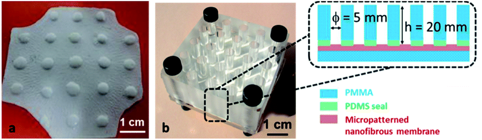 | ||
| Fig. 4 (a) A microstructured composite membrane with the 21 microstructured areas. (b) The membrane integrated in the biochip and its design. | ||
The biochips were used to screen in parallel the effect of the different fibrous architectures on the proliferation and activity of osteoblast-like MG-63 cells. The main role of osteoblasts is to produce and secrete organic and inorganic bone extracellular matrix (ECM), called ostoid.28 The organic bone matrix is constituted of various proteins, such as collagen, osteonectin, osteocalcin, and sialoproteins. The inorganic bone matrix is constituted of calcium–phosphate salts. Osteoconductivity of the various scaffold architectures was investigated by monitoring the proliferation and ECM forming activity of osteoblasts cultured in the biochip wells.
The morphology and spatial organization of the cells were evaluated by SEM observation after 3 days of cell culture. For the largest patterns such as Hex20,240, it is observed that cells preferentially adhered on the pattern walls where HA is located (Fig. 5a). Furthermore, MG63 cells show elongated morphology suggesting a good adhesion with the fibrous substrate (Fig. 5b and c). For the smallest patterns (i.e. when the distance between the HA areas is lower than 100 μm) the cells gathered, covering all the surface of the scaffold and began forming microtissues even after only 3 days of culture (Fig. S4 in ESI†). The proliferation and localization of MG63 osteoblasts on the micropatterned scaffolds was also observed by staining the cells nuclei with DAPI after 21 days of culture (see Fig. 6a–e and S1 in ESI†), showing the good proliferation of the cells into the structured wells of the biochip. As previously shown by SEM, a higher density of cells (i.e. stronger blue intensity) is observed where HA is deposited. For hexagonal patterns (Fig. 6a), this result seems to be in contradiction with our previous study20 for which a preferential location of MG-63 cells inside the nests of the honeycomb was observed. This difference could be explained by the presence of HA microparticles insuring a better affinity with the cells as compared with the hydrophobic surface of the PCL fibers. Indeed HA particles have shown to promote adhesion and growth of MG-63 cells.29
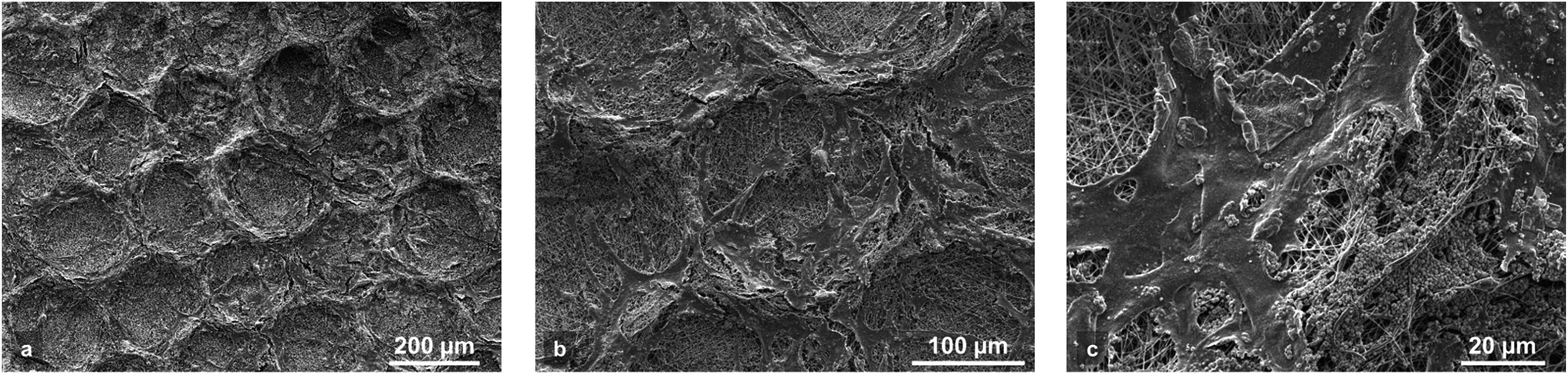 | ||
| Fig. 5 Morphology of MG63 cells observed by SEM after 3 days of culture on PCL–HA Hex20,240 bi-layer honeycomb patterns. (a) This picture shows that cells are mainly located on the honeycomb walls. (b) Detail of (a) showing elongated MG63 cells over a Hex20,240 pattern. (c) Detail of (b) showing cells and HA microparticles on a wall pattern. | ||
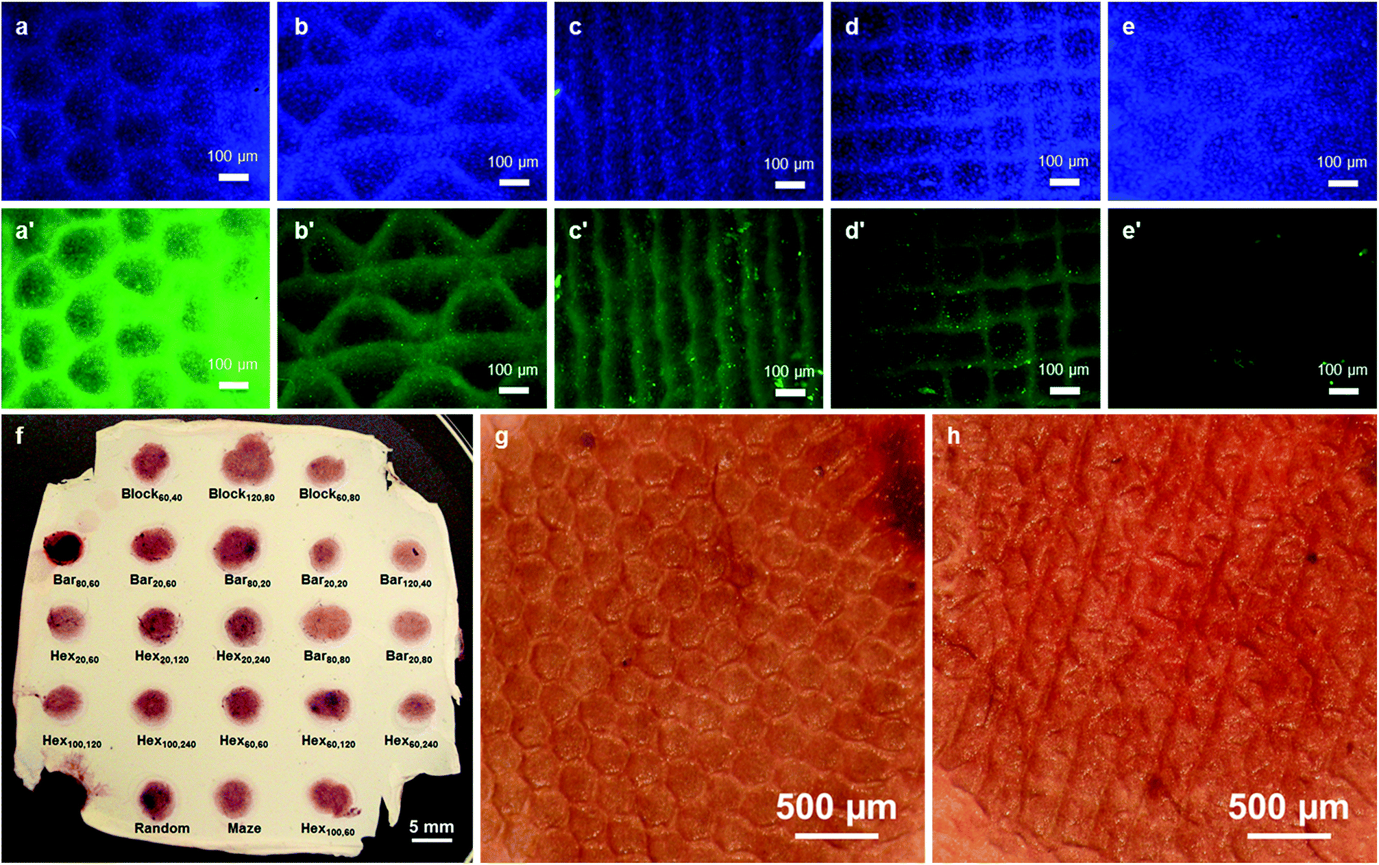 | ||
| Fig. 6 Observation of MG-63 osteoblasts after 21 days of culture in the biochip. (a and e) Observation of cell nuclei stained in blue with DAPI. (a′–e′) Observation of osteocalcin expression (OCN in green). (a and a′) Hex100,120; (b and b′) Maze20,80; (c and c′) Bar20,80; (d and d′) Block60,80; (e and e′) Hex20,240. (f) Characterization of the mineralization with Alizarin red coloration observed on a membrane after its removing from the biochip. (g) Stereomicroscope image of Hex60,240 after Alizarin red coloration. (h) Stereomicroscope image of Maze20,80 after Alizarin red coloration. | ||
The production of ECM by MG-63 cells was estimated by immunofluorescence assays. In contrast with DAPI, important differences are observed in the expression of osteocalcin by the cells as a function of the scaffold microstructure (Fig. 6a′–e′ and S2 in ESI†). It is obvious that some patterns show much higher fluorescence intensity than other types of patterns.
Finally, in order to evaluate the mineralization of the scaffolds by the MG-63 osteoblast-like cells, Alizarin red coloration of the membrane after 21 days of cell culture was performed. In this assay, calcium salts are stained in red and a stronger red intensity indicates the presence of higher amount of calcium salts. Because our membrane already contains a certain amount of hydroxyapatite, a negative control test has been carried out by Alizarin red coloration of a biochip membrane containing hydroxyapatite without cells (Fig. S3 in ESI†).
Fig. 6f shows a membrane after removing from the biochip and coloration by Alizarin red. A significant difference in Alizarin red intensity is observed, between this membrane, after cell culture, and an as-produced membrane, thus showing a good mineralization of the scaffolds. However, no significant differences in Alizarin red intensity could be distinguished between the different kinds of the micropatterned structures.
These results show that our biochip can be used for cell culture and are compatible with different kinds of biological tests. The membrane can be removed from the device after the cell culture and can be very easily manipulated for further observations such as microscopy.
4. Conclusions
In this article we showed a new electrospinning based process, the ETAD process, which allows the precise spatial deposition of microparticles by electrospraying onto a surface thanks to the “electrostatic template” effect obtained by electrospinning of a thin layer of non-conductive fibers onto microstructured collectors. This process can be used to prepare bilayered scaffolds with a wide range of 2D architectures and made of two different materials depending on the intended application.We used this process to elaborate a new kind of biochip, dedicated to the screening of fibrous composite structures for bone regeneration applications. The biochips contain 21 wells with different micropatterned structures such as hexagon, bar, block, and maze in their bottom. Each well structure was made of electrospun PCL fibers covered by a microstructured layer of hydroxyapatite particles. MG-63 osteoblasts-like cells were then successfully cultured into the different wells of the biochip and immunochemistry as well as biochemistry assays were performed as a proof of concept. The biochip can be very easily unbuilt at the end of the cell culture and the scaffold with various microstructures separated from the setup and manipulated for microscope observation or further biological, chemical or mechanical tests.
Acknowledgements
This study was supported by the Agence Nationale de la Recherche, France (project ANR-P2N 2011 NANO 018-01 NeoTissage). We also thank the cleanroom staff of STNANO in Strasbourg (France) for their technical support. We also thank Christophe Sutter and Thierry Djekriff for their help in the electrospinning set-up and Sébastien Gallet for Raman confocal microscopy.Notes and references
- M. Nikkhah, F. Edalat, S. Manoucheri and A. Khademhosseini, Biomaterials, 2012, 33, 5230–5246 CrossRef CAS PubMed.
- S. Ankam, B. K. Teo, M. Kukumberg and E. K. Yim, Organogenesis, 2013, 9, 128–142 CrossRef PubMed.
- K. Gupta, D. H. Kim, D. Ellison, C. Smith, A. Kundu, J. Tuan, K. Y. Suh and A. Levchenko, Lab Chip, 2010, 10, 2019–2031 RSC.
- L. D. A. Markert, J. Lovmand, M. Foss, R. H. Lauridsen, M. Lovmand, E.-M. Füchtbauer, A. Füchtbauer, K. Wertz, F. Besenbacher and F. S. Pedersen, Stem Cells Dev., 2009, 18, 1331–1342 CrossRef PubMed.
- H. V. Unadkat, M. Hulsman, K. Cornelissen, B. J. Papenburg, R. K. Truckenmüller, A. E. Carpenter, M. Wessling, G. F. Post, M. Uetz, M. J. T. Reinders, D. Stamatialis, C. A. van Blitterswijk and J. de Boer, Proc. Natl. Acad. Sci. U. S. A., 2011, 108, 16565–16570 CrossRef CAS PubMed.
- S. Ankam, M. Suryana, L. Y. Chan, A. A. K. Moe, B. K. K. Teo, J. B. K. Law, M. P. Sheetz, H. Y. Low and E. K. F. Yim, Acta Biomater., 2013, 9, 4535–4545 CrossRef CAS PubMed.
- A. A. K. Moe, M. Suryana, G. Marcy, S. K. Lim, S. Ankam, J. Z. W. Goh, J. Jin, B. K. K. Teo, J. B. K. Law, H. Y. Low, E. L. K. Goh, M. P. Sheetz and E. K. F. Yim, Small, 2012, 8, 3050–3061 CrossRef CAS PubMed.
- S. Agarwal, J. H. Wendorff and A. Greiner, Polymer, 2008, 49, 5603–5621 CrossRef CAS.
- D. Li, Y. Wang and Y. Xia, Adv. Mater., 2004, 16, 361–366 CrossRef CAS.
- D. Zhang and J. Chang, Nano Lett., 2008, 8, 3283–3287 CrossRef CAS PubMed.
- N. Lavielle, A. Hébraud, C. Mendoza-Palomares, A. Ferrand, N. Benkirane-Jessel and G. Schlatter, Macromol. Mater. Eng., 2012, 297, 958–968 CrossRef CAS.
- D. Ahirwal, A. Hébraud, R. Kádár, M. Wilhelm and G. Schlatter, Soft Matter, 2013, 9, 3164–3172 RSC.
- C. R. Wittmer, A. Hébraud, S. Nedjari and G. Schlatter, Polymer, 2014, 55, 5781–5787 CrossRef CAS.
- S. Nedjari, G. Schlatter and A. Hébraud, Mater. Lett., 2015, 142, 180–183 CrossRef CAS.
- B. Sun, Y. Z. Long, H. D. Zhang, M. M. Li, J. L. Duvail, X. Y. Jiang and H. L. Yin, Prog. Polym. Sci., 2014, 39, 862–890 CrossRef CAS.
- S. Cai, H. Xu, Q. Jiang and Y. Yang, Langmuir, 2013, 29, 2311–2318 CrossRef CAS PubMed.
- M. Simonet, N. Stingelin, J. G. F. Wismans, C. W. J. Oomens, A. Driessen-Mol and F. P. T. Baaijens, J. Mater. Chem. B, 2014, 2, 305–313 RSC.
- P. K-hasuwan, P. Pavasant and P. Supaphol, Langmuir, 2011, 27, 10938–10946 CrossRef CAS PubMed.
- Y. Liu, L. Zhang, H. Li, S. Yan, J. Yu, J. Weng and X. Li, Langmuir, 2012, 28, 17134–17142 CrossRef CAS PubMed.
- S. Nedjari, S. Eap, A. Hébraud, C. R. Wittmer, N. Benkirane-Jessel and G. Schlatter, Macromol. Biosci., 2014, 14, 1580–1589 CrossRef CAS PubMed.
- D. Gallego-Perez, N. Higuita-Castro, S. Sharma, R. K. Reen, A. F. Palmer, K. J. Gooch, L. J. Lee, J. J. Lannutti and D. J. Hansford, Lab Chip, 2010, 10, 775–782 RSC.
- Y. Lee, H. J. Lee, K. J. Son and W. G. Koh, J. Mater. Chem., 2011, 21, 4476–4483 RSC.
- H. J. Lee, H. S. Kim, H. O. Kim and W. G. Koh, Lab Chip, 2011, 11, 2849–2857 RSC.
- P. Wutticharoenmongkol, N. Sanchavanakit, P. Pavasant and P. Supaphol, Macromol. Biosci., 2006, 6, 70–77 CrossRef CAS PubMed.
- D. Gupta, J. Venugopal, S. Mitra, V. Giri Dev and S. Ramakrishna, Biomaterials, 2009, 30, 2085–2094 CrossRef CAS PubMed.
- I. H. L. Pereira, E. Ayres, L. Averous, G. Schlatter, A. Hebraud, A. C. C. De Paula, P. H. L. Viana, A. M. Goes and R. L. Oréfice, J. Mater. Sci.: Mater. Med., 2014, 25, 1137–1148 CrossRef CAS PubMed.
- D. Li, Y. Wang and Y. Xia, Nano Lett., 2003, 3, 1167–1171 CrossRef CAS.
- J. R. Porter, T. T. Ruckh and K. C. Popat, Biotechnol. Prog., 2009, 25, 1539–1560 CAS.
- S.-J. Heo, S.-E. Kim, J. Wei, Y.-T. Hyun, H.-S. Yun, D.-H. Kim, J. W. Shin and J.-W. Shin, J. Biomed. Mater. Res., Part A, 2008, 89, 108–116 Search PubMed.
Footnote |
| † Electronic supplementary information (ESI) available: ESI includes fluorescent microscopy of MG-63 osteoblasts cell nuclei and osteocalcin expression after 21 days of culture. See DOI: 10.1039/c5ra15931h |
| This journal is © The Royal Society of Chemistry 2015 |