DOI:
10.1039/C5RA15486C
(Paper)
RSC Adv., 2015,
5, 98553-98558
A comparison of centrifugally-spun and electrospun regenerated silk fibroin nanofiber structures and properties
Received
3rd August 2015
, Accepted 9th November 2015
First published on 11th November 2015
Abstract
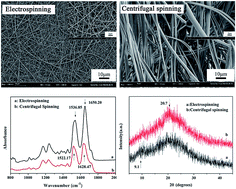
Recently, a newly-developed approach to fabricate nanofibers, centrifugal spinning, has been paid great attention for its wider material choice, higher production rate, and lower cost compared with electrospinning. However, the structure and property differences of nanofibers obtained from these two methods are unclear. In this paper, we will take regenerated silk fibroin (i.e., RSF) nanofibers as an example to reveal the differences. The centrifugally-spun and electrospun RSF nanofibers were spun under the same solution and environment. The morphology, secondary structure, orientation, and thermal properties of the two types of RSF nanofiber aggregation structures were characterized by Field-Emission Scanning Electron Microscopy (FESEM), Fourier Transform Infrared Spectroscopy (FTIR), Far Infrared (FIR), Wide Angle X-ray Diffraction (WXAD), Optical Polarizing Microscopy (OPM), Differential Scanning Calorimetry (DSC), and Thermogravimetric Analysis (TGA), respectively. The conformations of the RSF were transformed from random coil to β-sheet, and at the same time, the crystallinity, orientation, and thermostability were all enhanced through centrifugal spinning. The findings suggest that centrifugal spinning is a more promising approach to fabricate RSF fibers with stable structures and outstanding performances compared with electrospinning.
Introduction
Nanofibers have attracted lots of research attention due to their unique properties and extensive applications in many fields, involving biomaterials,1 energy storage,2 environment,3 etc. Thereupon, a large number of nanofabrication techniques emerge, such as self-assembly, template-directed, phase separation, etc. However, the developments of these techniques are limited. Self-assembly methods build nanofibers via weak interactions such as hydrogen bonding and hydrophobic interaction,4 which are useless in most practical applications. Template-directed approach could control size strictly,5 but the process of removal template with organic solvent would easily destroy the nanostructure. Phase separation only applied to a few polymers.6
Electrospinning can partly overcome the limitations encountered by the above-mentioned methods. It is a flexible and potential method to process nanofibers with uniform in diameter and long in length. The fiber diameter can be easily controlled through varying some technical parameters such as applied voltage, nozzle-collector distance, feeding rate, polymer solution concentration, etc. According to the statistics, more than 50% of the research articles related to nanofibers are based on electrospinning,7 including spinning mechanisms,8 various fiber mats preparations and applications.9 However, there are two critical factors prevent electrospinning from laboratory to industrial production which still in the infancy with slow development. First, electrospinning only fits polar solutions, which results in big limitations on raw material choices. Nonpolar solutions mixed polar molecules can also be spun, but dopants are undesired. Second, low productivity is generally considered as a problem that can't be ignored. The low production rate of a single needle is only 0.1–1.0 g h−1. Some novel measures were used to develop the problem, which are generally focused on the number and shape of needles. However, the interfering electric fields of nearby needles and the troublesome cleaning system limit the application of multi-needles.10 Needleless electrospinning can be used to develop production rate, up to 5.23 g h−1 for PVP,11 while the result is far from satisfying.
When centrifugal spinning spring up for producing polymer nanofibers, many researchers have interest in this method due to the rapid production rate, wide material choice, and low cost.12 The nanofibers are created through centrifugal forces, so both polar and nonpolar solutions can be spun via centrifugal spinning. So far, the reports related to centrifugal spinning almost concentrated upon preparing various kinds of nanofibers with diverse materials and their applications, for example, PVDF,13 ITO,14 PAN,15 etc. In their views, centrifugal spinning was comparable to electrospinning and was a more suitable method to industrial production because of the efficiency and diversity of raw materials. However, up to now, detailed comparisons between centrifugal spinning and electrospinning have been rarely reported, especially two types of nanofibers on structures and properties.
In this paper, we aim to investigate the differences of the two nanofibers obtained from centrifugal spinning and electrospinning. Regenerated silk fibroin (RSF) is treated as an object of study because it can be spun via centrifugal spinning and electrospinning under the same concentration and environment simultaneously. The two types of RSF nanofibers are compared on morphologies, secondary structures, orientations and thermal properties.
Experimental
Materials
Cocoons of Bombyx mori silkworm silk were obtained from TongXiang, ZheJiang Province, China. All chemicals were purchased from Aladdin (Shanghai, China) and were used without further purification.
Preparation of regenerated Bombyx mori silk fibroin spinning solution
Cocoon shells were degummed with 0.5% (w/w) Na2CO3 solution at 95 °C for 30 min and then rinsed thoroughly with deionized water in order to extract sericin from the surface of silk fibers. Usually, this treatment was repeated four times. The degummed cocoon shells were then added to 20 times (v/w) of a ternary solvent system of CaCl2/CH3CH2OH/H2O (1
:
2
:
8 in molar ratio). The mixture was stirred at 70 °C for 0.5 h to form a clear solution. The resulting fibroin solution was dialyzed with a cellulose tubular membrane (molecular weight cut-off 8000–14
000 Da) in running water for two days and then dialyzed in deionized water for two days. After that, the silk fibroin solution was filtered and lyophilized to obtain the regenerated silk fibroin sponges. Then regenerated silk fibroin sponges were dissolved in formic acid (98%) with concentrations of 20 wt%. To prevent solvent evaporating during stirring, the mixture was sealed in a reagent bottle.
Nanofiber preparations
Centrifugal spinning. The centrifugal spinning setup is shown in Fig. 1, including needle, spinneret, annular fiber collector, and motor. The needle (l = 1 cm, d = 0.2 mm) is mounted on the spinneret. The spinneret is fixed on a shaft which is controlled by the motor. In this study, the rotational speed of the spinneret was controlled at 4000 rpm. The distance between the needle tip and the rod collector was 12 cm.
 |
| Fig. 1 Centrifugal spinning system. (a) needle, (b) spinneret, (c) annular fiber collector, (d) motor. | |
Electrospinning. The setup of the electrospinning system is ordinary and the corresponding schematic diagram is shown in Fig. 2, including high voltage power supply, needle (I = 1 cm, d = 0.8 mm), syringe (10 ml), and collector with aluminum foil. The size of needle was determined in practical operation. Thinner needle would be blocked easily, which went against spinning continuously. The tip-to-collector distance was set at 12 cm. Instead of the rotational speed of the spinneret in the centrifugal spinning system, the high voltage provided by the power supply was adjusted at 21 kV.
 |
| Fig. 2 A schematic diagram of electrospinning setup. | |
Nanofiber characterizations
Field-emission scanning electron microscope (FESEM). The gold sputtered centrifugally-spun and electrospun fibers were examined on a ZEISS type-ULTRA55 scanning electron microscope. Image Pro Plus 6.0 was used to measure the diameters of the fibers. The average fiber diameter and distributions were determined from 100 random fibers obtained from each spinning condition.
Fourier transform infrared spectroscopy (FTIR). A Nicolet 5700 FTIR spectrometer was utilized to obtain the spectra of samples mixed with potassium bromide (KBr) and pressed into pellets. The spectra were taken over a range of 800–2000 cm−1 with a resolution of 4 cm−1 using 32 scans.
Far infrared (FIR). A Bruker VERTEX 80v far-infrared spectrometer was used to achieve the spectra of fiber mats at thicknesses of 100 μm. The spectra were gathered in range from 30 to 680 cm−1 with a resolution of 2 cm−1 using 64 scans.
Wide angle X-ray diffraction (WAXD). WAXD diffraction curves were recorded on a Thermo ARL-XTRA X-ray diffractometer equipped with a Cu Kα radiation. The diffraction intensities were measured every 2° from 2θ = 5° to 45° at a rate of 2θ = 2° min−1. The supplied voltage and current were 30 kV and 20 mA, respectively.
Optical polarizing microscopy (OPM). A Leica DM2700 optical polarizing microscopy used to characterize the morphology and birefringence of centrifugally-spun and electrospun fibers. The fibers were directly deposited onto a glass slide for microscopy analysis.
Differential scanning calorimeter (DSC) and thermogravimetric analysis (TGA). The thermographs were acquired using a Mettler Toledo differential scanning calorimeter and a thermogravimetric analysis. The DSC curves were obtained from room temperature to 285 °C at a heating rate of 10 °C min−1 under a nitrogen gas. The TGA curves were acquired from room temperature to 450 °C at a rate of 10 °C min−1 under a nitrogen gas.
Results and discussion
To make sure the comparability, the properties of spinning solution were consistent both in centrifugal spinning and electrospinning. Only spinning methods were different in the experiments. Uniformly centrifugally-spun and electrospun fibers were selected on the basis of a mass of experiments.
Results obtained from experiments indicated that large amounts of centrifugal fibers with few beads were achieved when the concentration at 20 wt%, tip-to-collector distance at 12 cm, and the rotational speed at 4000 rpm. In electrospinning, the spinning solution concentration and tip-to-collector distance remained unchanged. Uniformly electrospun fibers were achieved when voltage at 21 kV.
Surface morphology
The SEM images of candidates are shown in Fig. 3. It was noted that the mean fiber diameter of centrifugal was obviously thicker than that of electrospun. What's more, the centrifugally-spun fiber mats presented a broader fiber diameter distribution and more beads. In electrospinning, a jet was formed from a tapering cone, through a series of successively smaller electrically driven bending coils, and finally solidifying into a continuous thin fiber.16 The free charges came outward the fiber surface and accumulated at the interfaces. The charge–charge repulsion force was in favour of the diminution of jet. Besides, branches observed during electrospinning also help to result in the thinner fibers. In centrifugal spinning, with jet travelling, the centrifugal force decreased and viscous force increased gradually. The jet would break up if the balance of centrifugal force, viscous force and surface force was destroyed.17 However, no forces would be exerted on the break-up jets of centrifugal spinning. Although air friction occurring at the interface of jet and gas layer might promote jet elongation, airflow also accelerated an evaporation rate of solvent, in which case the time of jets dragging would be shorter leading to the thicker fibers. Another difference could be found that the centrifugally-spun fiber mats were loosely packed compared with densely-packed fiber mats prepared by electrospinning under the same amount of spinning solution. In electrospinning, the fibers were intensively deposited on the collector by the electric field force, resulting in a compact structure. Nevertheless, spiral break-up jets in centrifugal spinning freely extend outwards until arrive at the annular collector, where fibers intertwine to fiber mats.
 |
| Fig. 3 FESEM images of electrospun RSF fibers (A) 200×, (B) 1000×, (C) 5000×, and centrifugally-spun fibers (D) 200×, (E) 1000×, (F) 5000×. Diameter distributions of fibers: (G) electrospun fibers and (H) centrifugally-spun. | |
Secondary structure
The secondary structure of Bombyx mori silk fibroin consists of the major conformations including random coils (silk I) and β-sheets (silk II).18 It is commonly believed that β-sheets are stable structures and endow silk fibers with excellent mechanical properties. Amid I and amid II regions have been often applied to study the secondary structure of silk fibroin fibers or films. As shown in Fig. 4, there were significant conformational differences between the two types of fibers. Two distinct bands had nearly been confirmed the contributions from random coil and β-sheet conformations at 1660 cm−1 and 1628 cm−1 in amid I, respectively. The electrospun fibers were characterized by absorption bands at 1650.20 cm−1, whereas centrifugally-spun fibers were at 1628.47 cm−1 in this region. The conformations of electrospun fibers were assigned to random coil, the conclusion of which is the same with that of Rusa et al.19 However, band position of centrifugally-spun fibers in this region suggests a β-sheet conformation, which can be interpreted by more H-bonds between C
O groups in the centrifugal spinning system. A similar observation could be found in amid II. The absorption band of electrospun samples at 1536.85 cm−1, around 1540 cm−1, was usually considered as the random coil conformation. On the other hand, the centrifugally-spun fibers showed an absorption brand at 1522.17 cm−1, attributed to the β-sheet conformation. As shown in Fig. 5, a small segment of centrifugal jet was formed under the influence of centrifugal force (Fcentr), viscous force (Fvisc), and Coriolis force (Fcor).17 However, electrostatic force and repulsive Coulomb forces of charges were exerted on an electrospun jet except molecular interactions (surface tension and viscoelasticity). The different forces in each spinning system maybe the reason why the conformational transformation. Moreover, Andrea et al. reported that different preparation methods may result in extended chain conformation very different.20 Similar results were observed in our repeated experiments. Therefore, we deduce that centrifugal spinning system converts the conformation of SF from random coil to β-sheet more easily.
 |
| Fig. 4 FTIR spectra of RSF fibers: (a) electrospun fibers, and (b) centrifugally-spun fibers. | |
 |
| Fig. 5 Forces on a small segment of centrifugally-spun jet.17 | |
Far infrared is attempted to explore the conformation of the two fibers, as shown in Fig. 6(A). It was noted that some peaks were observed in centrifugally-spun curve at 550 cm−1, 331 cm−1, 239 cm−1, 121 cm−1, corresponding to some similar peaks in electrospun curve at 555 cm−1, 336 cm−1, 241 cm−1, 125 cm−1. Similar results can be obtained in Fig. 6(B). We deem that these peaks may be the characteristic peaks of silk fibroin. However, the spectrograms of the two fibers were greatly different, which indicated the differences on structure. The relative strength of electrospun absorption peaks obviously exceeded that of centrifugal. As shown in Fig. 6(C) and (D), a distinct gap appeared between high and low frequency for electrospun samples, while it is unconspicuous with centrifugally-spun samples. In principle, the functions of covalent bond and hydrogen bond, or the molecular rotations may lead to this consequence.21,22
 |
| Fig. 6 (A) FIR spectra of RSF fibers: (a) electrospun fibers, and (b) centrifugally-spun fibers. (B) A repeated result. The transmission signal of fibers in (A): electrospun sample (C) and centrifugal sample (D). | |
The crystal structure transition in X-ray patterns of centrifugally-spun and electrospun fibers are compared in Fig. 7. There were diffraction peaks for both fibers at 9.1°, suggesting that the presence of β-sheets. The diffraction curves of centrifugally-spun fibers exhibited a poignant peak rather than a broad peak for electrospun fibers centered at 20.7°, indicating that the crystallinity of the former was higher. The break-up jets are in airflow field and electric field, respectively. The force of the spinning solution suffered, centrifugal force or electrostatic force, could easily influence the crystallization of RSF.23 Although the tip-to-collector distance was invariable in these two spinning systems, the traveling time of jets was different when molecular rearrangement and crystallization occurred before depositing on the collector due to different shear forces. The higher crystallinity indicates that an increase in the β-sheet of the centrifugally-spun fibers, which confirms results of FTIR spectroscopy. Therefore, centrifugal spinning develops the crystallinity of fibers.
 |
| Fig. 7 WAXD patterns of RSF fibers: (a) electrospun fibers, and (b) centrifugally-spun fibers. | |
Orientation
To verify the different orientation of the two types of fibers, optical polarizing micrographs are shown in Fig. 8. Birefringence was observed from rotating fibers under cross-polarized optical, indicating the presence of chain orientation and/or crystallization.24 The orientation is positively related to the brightness. It was not difficult to find that the centrifugally-spun fibers were lighter, which indicated higher orientation. The resultant force exerted on centrifugal jets was always parallel to the axis of fibers (Fig. 5), which was in favour of molecular orientation. Conversely, the repulsive Coulomb forces between the adjacent charges in perturbed segments of the electrospun jet were forced perpendicular to fiber axis, which worked against the elongation of molecular in the direction of its axis. Moreover, the directions of Coulomb forces were fluctuant due to first or higher order bending instability in electrospinning.
 |
| Fig. 8 Birefringence of RSF fibers under optical polarizing microscopy: (a) electrospun fibers, and (b) centrifugally-spun fibers. | |
Thermal properties
The DSC thermograms of the two types of fibers are compared in Fig. 9. Both two samples exhibited two endothermic peaks around 80 °C and 280 °C. The former is attributed to the evaporation of absorbed water and the latter is attributed to the thermal decomposition of silk fibroin.25 Another transition is observed in the vicinity of 160 °C followed by an exotherm in both curves, which is attributed to the glass transition of the silk fibroin. It was noted that a small exothermic peak appeared at 230 °C for the electrospun fibers, indicating a crystallization of β-crystallites from the random coil occurred.26 Conversely, no obvious exothermic peak for the centrifugally-spun fibers was observed at 230 °C. The thermo analysis results demonstrate that the content of β-sheet of centrifugally-spun fibers is higher than that of electrospun fibers, which are consistent with the conclusion achieved from FTIR. In addition, an interesting phenomenon that relatively higher decomposition temperature of centrifugally-spun fibers was discovered in several repeated experiments. It is believed that the intermolecular interactions increase with highly ordered crystal structures of centrifugally-spun RSF fibers, which make it difficult to decompose.
 |
| Fig. 9 DSC curves of RSF fibers: (a) electrospun fibers, and (b) centrifugally-spun fibers. | |
Thermogravimetric curves of the RSF fibers are shown in Fig. 10. There were three zones of weight loss for electrospun fibers but only two observed in centrifugally-spun fibers. The initial weight loss of the both fibers below 100 °C is due to loss of moisture. Moreover, another weight loss of the both fibers occur around 275 °C, which indicating the fibers begin to decompose. However, about 5% weight loss only happened in electrospun fibers at the temperature in the range of 190 to 260 °C. It obviously confirms that the thermostability of centrifugally-spun fibers is better. The conclusion also states structures of centrifugally-spun fibers are more orderly and regular, which is consistent with the result of DSC (Fig. 9).
 |
| Fig. 10 Thermogravimetric curves of RSF fibers: (a) electrospun fibers, and (b) centrifugally-spun fibers. | |
Conclusions
The differences of two RSF nanofibers obtained from centrifugal spinning and electrospinning on the structures and properties had been discussed in this paper. More random coils of centrifugally-spun RSF nanofibers can be transformed into β-sheet than that of electrospun, leading to enhanced structural stabilities and thermostabilities of centrifugally-spun RSF nanofibers. The shear stress and spiral path of centrifugal spinning led the macromolecule movements were along the axis of fibers of RSF macromolecule, whereas the bending instabilities worked against that in electrospinning. Consequently, centrifugal spinning is a promising method to fabricate regenerated silk fibroin fibers with superior performances, which will help to improve the application areas of RSF nanofibers.
Acknowledgements
This work was supported by Zhejiang Top Priority Discipline of Textile Science and Engineering (2014KF02) and Zhejiang Leading Team of Science and Technology innovation (2011R50004).
References
- A. J. Meinel, K. E. Kubow, E. Klotzsch, M. Garcia-Fuentes, M. L. Smith, V. Vogel, H. P. Merkle and L. Meinel, Biomaterials, 2009, 30, 3058–3067 CrossRef CAS PubMed.
- L. W. Ji and X. W. Zhang, Carbon, 2009, 47, 3219–3226 CrossRef CAS.
- V. Thavasi, G. Singh and S. Ramakrishna, Energy Environ. Sci., 2008, 1, 205–221 CAS.
- Z. M. Yang and B. Xu, J. Mater. Chem., 2007, 17, 2385 RSC.
- C. R. Martin, Science, 1994, 266, 1961–1966 CAS.
- P. X. Ma and R. Y. Zhang, J. Biomed. Mater. Res., Part A, 1999, 46, 60–72 CrossRef CAS.
- K. Sarkar, C. Gomez, S. Zambrano, M. Ramirez, E. de Hoyos, H. Vasquez and K. Lozano, Mater. Today, 2010, 13, 12–14 CrossRef CAS.
- D. H. Reneker and A. L. Yarin, Polymer, 2008, 49, 2387–2425 CrossRef CAS.
- B. Marelli, A. Alessandrino, S. Fare, G. Freddi, D. Mantovani and M. C. Tanzi, Acta Biomater., 2010, 6, 4019–4026 CrossRef CAS PubMed.
- S. A. Theron, A. L. Yarin, E. Zussman and E. Kroll, Polymer, 2005, 46, 2889–2899 CrossRef CAS.
- J. Holopainen, T. Penttinen, E. Santala and M. Ritala, Nanotechnology, 2015, 26, 025301 CrossRef CAS PubMed.
- X. W. Zhang and Y. Lu, Polym. Rev., 2014, 54, 677–701 CrossRef CAS.
- T. P. Lei, X. M. Cai, X. Wang, L. K. Yu, X. W. Hu, G. F. Zheng, W. L. Lv, L. Y. Wang, D. Z. Wu, D. H. Sun and L. W. Lin, RSC Adv., 2013, 3, 24952 RSC.
- A. Altecor, Y. Mao and K. Lozano, Funct. Mater. Lett., 2012, 05, 1250020 CrossRef.
- Y. Lu, Y. Li, S. Zhang, G. J. Xu, K. Fu, H. Lee and X. W. Zhang, Eur. Polym. J., 2013, 49, 3834–3845 CrossRef CAS.
- D. H. Reneker and A. L. Yarin, Polymer, 2008, 49, 2387–2425 CrossRef CAS.
- H. Z. Xu, H. H. Chen, X. L. Li, C. Liu and B. Yang, J. Polym. Sci., Part B: Polym. Phys., 2014, 52, 1547–1559 CrossRef CAS.
- J. Ayutsede, M. Gandhi, S. Sukigara, M. Micklus, H.-E. Chen and F. Ko, Polymer, 2005, 46, 1625–1634 CrossRef CAS.
- C. C. Rusa, C. Bridges, S.-W. Ha and A. E. Tonelli, Macromolecules, 2005, 38, 5640–5646 CrossRef CAS.
- A. Camposeo, I. Greenfeld, F. Tantussi, S. Pagliara, M. Moffa, F. Fuso, M. Allegrini, E. Zussman and D. Pisignano, Nano Lett., 2013, 13, 5056–5062 CrossRef PubMed.
- A. Matei, N. Drichko, B. Gompf and M. Dressel, Chem. Phys., 2005, 316, 61–71 CrossRef CAS.
- A. Paciaroni, V. Conti Nibali, A. Orecchini, C. Petrillo, M. Haertlein, M. Moulin, M. Tarek, G. D'Angelo and F. Sacchetti, Chem. Phys., 2013, 424, 80–83 CrossRef CAS.
- H. S. KIm, Y. S. Nam, T. S. Lee and W. H. Park, Polym. J., 2003, 35, 185–190 CrossRef.
- C. Li, C. Vepari, H. J. Jin, H. J. Kim and D. L. Kaplan, Biomaterials, 2006, 27, 3115–3124 CrossRef CAS PubMed.
- N. Agarwal, D. A. Hoagland and R. J. Farris, J. Appl. Polym. Sci., 1997, 63, 401–410 CrossRef CAS.
- C. Chen, C. B. Cao, X. L. Ma, Y. Tang and H. S. Zhu, Polymer, 2006, 47, 6322–6327 CrossRef CAS.
|
This journal is © The Royal Society of Chemistry 2015 |
Click here to see how this site uses Cookies. View our privacy policy here.