Sediment microbial fuel cells as a new source of renewable and sustainable energy: present status and future prospects
Atieh Zabihallahpoor
a,
Mostafa Rahimnejad
*ab and
Farid Talebnia
ab
aBiofuel & Renewable Energy Research Center, Faculty of Chemical Engineering, Babol Noshirvani University of Technology, Babol, Iran. E-mail: Rahimnejad_mostafa@yahoo.com; rahimnejad@nit.ac.ir; Fax: +98 1132334204; Tel: +98 1132334204
bAdvanced Membrane & Biotechnology Research Center, Faculty of Chemical Engineering, Babol Noshirvani University of Technology, Babol, Iran
First published on 28th September 2015
Abstract
Active biocatalysts such as microorganisms or enzymes liberate electrons while electron donors are consumed in biological fuel cells. Biological fuel cells are a novel technology producing bio-electrochemical power using various materials such as complex organic waste or natural organic matter under anaerobic anode conditions. Recently, great attention has been paid to biological fuel cells due to their mild operating conditions and use of a variety of biodegradable substrates as fuel. Sediment microbial fuel cells (SMFCs) are a kind of microbial fuel cell (MFC) that can produce electrical current from the organic matter content of sediment using bacterial metabolism. SMFCs have been developed in the past decade to provide a renewable power source and organic matter removal. SMFCs differ from other MFCs due to their essentially complete anoxic conditions at the anode and their membrane-less structure. To further improve SMFC technology, this paper focuses on the limitations and challenges of SMFCs and collects the latest surveys in this field.
1. Introduction
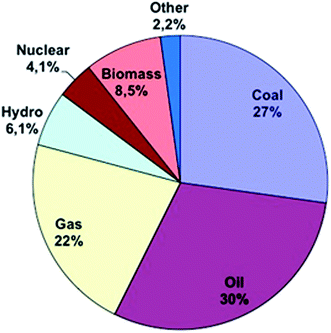
Energy is needed to preserve life. Different kinds of energy are formed and used in different countries. This energy is dissipated into the atmosphere and disrupts normal atmospheric circulation patterns, which cause changes in the Earth’s atmosphere, temperature, greenhouse effect etc.1 Fossil fuel energy is the basic engine for growth in many economies. Energy consumption is related to economic growth.2 So in recent years, energy consumption has grown exponentially in developing economies.3 As can be seen in Fig. 1, most of the energy consumed in the world in 2012 was non-renewable energy. For example according to the U.S. Energy Information Administration, only 8% of energy consumption in 2010 in the USA came from renewable energy sources versus 9% from nuclear energy and others from non-renewable energy sources. Although energy sources have shifted from fossil fuels to renewable energy sources, oil and gas are still the major primary energy sources powering the world’s industries. So the demand for new renewable energy sources still remains.Energy needs are increasing around the world and traditional sources of energy such as fossil fuels have several disadvantages. Alternative sources of energy are required. Most of the energy sources used around the world are non-renewable energy sources. This kind of energy sources is running out and their utilization causes problems like emission of greenhouse pollutants, including SOx, COx, NOx, CxHy, soot, ash, droplets of tar, and other organic compounds, which are released into the atmosphere as a result of their combustion. Also, fossil fuels are inefficient sources for preparing energy requirements due to pollution and finite supplies.3–5 So, the researchers round the world are working to find new energy platforms to provide sufficient energy without CO2 emission and greenhouse gas problems.5,6 Many countries all over the world have made an effort to solve the energy crisis by turning their attention to renewable energy sources such as solar energy or energy derived from wind or water. One renewable alternative energy source is the fuel cell, which has attracted lots of attention for generating energy. Fuel cells have several advantages such as no emission of environment polluting gases (such as SOx, NOx, CO2, CO), higher efficiency, no mobile parts and, as a result, and a lack of sonic pollution, etc.7,8 In contrast, high costs as well as mass generation are the only disadvantages of these new energy sources.7,9 There are several kinds of fuel cells. One of the most interesting fuel cells is the microbial fuel cell (MFC). MFCs were discovered by Potter. In 1911, Potter observed electrical current generated by bacteria. Until the early 1990s, few studies were made in this field.10 Over the last 20 years and especially in this last decade, we have observed a rapid development in MFC technologies.11,12
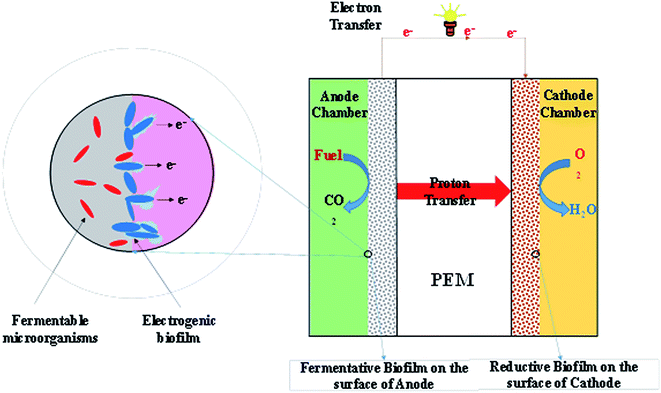
MFC technologies represent a novel energy harvesting technology and energy transducer and comprise an anaerobic anode, an aerobic cathode and typically a cation exchange membrane. The two electrodes are connected via a conductive wire.11,13–15 Fig. 2 shows the essential concept of an MFC. Microorganisms or active biocatalysts break down organic matter in their surrounding environment.6,16,17 Some MFCs need artificial electron mediators for transfer of electrons produced by biocatalysts from the substrate to the anode electrode.17–20 H+ or other cations pass through the anodic chamber to the cathode chamber by a proton exchange membrane. The resultant electrons from the organic matter degradation are transferred through the cathode via an external circuit and reduce oxygen according to reaction (1):11,13,16,21
| O2 + 4e− + 4H+ → 2H2O | (1) |
MFCs are able to harvest electricity from different substrates.6,19,22,23 In addition to liquid phase substrates, solid phase substrates such as sediments, sludge and contaminated soil can be fuel for solid state microbial fuel cells.24
Sediments in aquatic environments are a potentially long-term source of water contamination. Soil and sediments are derived from plant and animal detritus, settlement of dead bacteria and plankton, fecal matter and anthropogenic organic materials.25 Sediments’ organic carbon content generally ranges from 0.4 to 2.2 wt%.26 Thus, sediments’ organic carbon content may be seen as a sufficient energy resource in some locations. Many high cost and energy consumption physicochemical methods have been practised for sediment remediation.27 But this organic carbon content can be consumed by exoelectrogens directly transporting electrons outside of the cell. Sediment bioremediation by sediment microbial fuel cells (SMFCs) was recently developed due to its cost-effectiveness and environmental benignity.27 An SMFC is a simple configuration of an MFC, which generates electricity from the aquatic environment.
SMFCs are a bioelectricity production technique for low-power applications. SMFCs enhance organic matter removal (oxidation) from submerged soil at the anode along with energy production. In fact, SMFCs are membrane-free MFCs and their unique property of removing organic compounds from sediment has attracted significant attention recently.
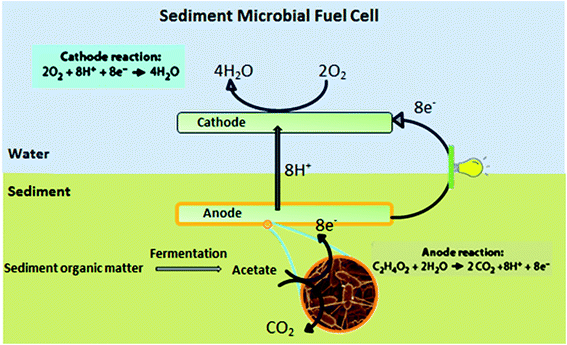
SMFCs consist of an anode electrode embedded in an anaerobic sediment connected through an electrical circuit to a cathode electrode suspended in overlying water28,29 (Fig. 3). Unlike conventional MFCs, SMFCs do not require protons to be transferred via a dissolved oxygen gradient along the water depth or a membrane.30–32 SMFCs differ from other MFCs in that the anode is essentially under completely anoxic conditions.10 Inspired by the experiments of Reimers and Tender, the first functional SMFCs were created about 10 years ago.25,33,34
Marine environments, rivers, fresh water, rice paddies and other aquatic sediments rich in organic matter have been used in various surveys.35,36 Marine microbial fuel cells (MMFCs) and benthic microbial fuel cell (BMFCs) are also known as SMFCs.
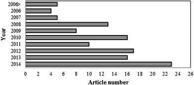
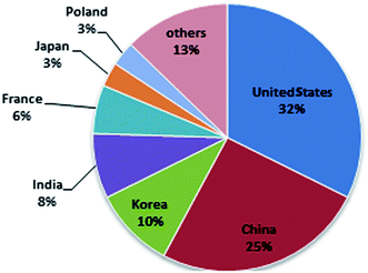
SMFCs are a special kind of MFC that generate bioelectricity by using an active microorganism from the sediment. Although the electrical current produced by bacteria was observed by Potter in 1911,37 limited feasible results were obtained in this subject in the next 50 years.38 At the beginning of the year 1990, the attraction of fuel cells became stronger and the field of MFCs and SMFCs began to improve.39 The steep slope of MFC progress began in 1999 when it was discovered that a mediator was not a required component.40,41 But interest in SMFCs has increased in recent years. Until now, limited research has been done on SMFC scale-up. In general, the most significant investigations on sediment microbial fuel cells have been conducted by Tian-Shun Song,24,29,42–44 Chun-Chong Fu45–48 and Seok Won Hong.25,49–51 Recently, there has been a rise in the number of published articles on this subject with the United States of America being the major source of such publications. The number of articles in the field of SMFCs from 2006 to 2014 is presented in Fig. 4 having used the key words “sediment microbial fuel cell” in a Scopus search.
Fig. 5 presents the different countries that are working on SMFCs. From Fig. 5, you can understand that all areas in the world have an interest in working in this renewable research area.
2. Mechanism
Microorganisms and substrates play important roles in SMFC performance. Fig. 6, illustrates the role of microorganisms in SMFCs with a number of main reactions which are determined to occur at the anode and cathode. The anode biofilm is enriched by two types of sedimentary microorganisms: the Geobacteracea family (most similar to Desulfuromonas acetoxidans) and the Desulfobulbus or Desulfucapsa genera. Geobacteracea oxidizes acetate in the sediment directly reducing the anode, while the Desulfobulbus or Desulfucapsa genera oxidize anode generated S0 to SO42−.52–54 Acetate is provided by organic matter fermentation by other anaerobic microorganisms in sediment (e.g., Clostridium). Another reaction occurring at the anode is the oxidation of S2− to S0. When organic matter is oxidized, O2, MnO2, Fe2O3 and SO42− reduce in order between the sediment surface layer and anode. With increasing sediment depth, each layer accumulates more and more potent reductants.52–55 So, as illustrated in Fig. 6, electrons produced by an active biocatalyst can be delivered to the anode from (1) microbes enriched on the anode surface, or (2) from the dissolved and solid-phase forms of reduced ions contained in the sediment (e.g., sulfides in marine sediment).50 Some MFCs need electron mediators to transfer the produced electrons to the anode surface17,18,20,56 and also a proton exchange membrane to transfer generated protons to the cathode chamber.57,58 But SMFCs do not need proton exchange membranes nor electron mediators.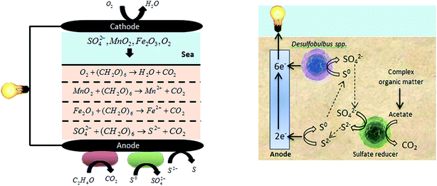 | ||
| Fig. 6 Microorganism roles and main reactions in SMFCs.59,60 | ||
3. Advantages
SMFCs have a number of functional advantages compared to other energy sources. These include direct conversion of organic matter into current at a high efficiency, working under a wide range of environmental conditions including low operating temperatures,34,35 low cost,61 less frequent maintenance requirements (e.g. periodic replacement),53 simple construction, wide varieties of and cheap fuel sources,34 and they can be easily placed in remote locations62 and have no generation of toxic components.63 On the other hand, SMFCs have some limitations such as nonlinear scaling up, low operating voltages, low cell potentials53,62,64 and a failure to provide continuous power.654. Applications
Two broad applications are discussed for sediment microbial fuel cells within the literature: (1) providing renewable power sources for instruments deployed in marine environments, rivers, lakes, freshwater, oceans etc. for long-term monitoring; and (2) removal of organic matter from sediments. In the following, each of these applications is explained separately.4.1. Renewable power sources
One of the main applications of SMFCs is to provide a power source for wireless equipment used for environmental monitoring, oceanographic studies, and military tactical surveillance where real-time data acquisition from remote locations is required35,65 (Table 1). These instruments have no cable connection with the surface, such that they need a kind of power supply such as a battery. However, batteries are associated with limited calendar lifetimes due to their requiring high cost periodic replacement, especially in deep water.34 These challenges can be overcome by applying SMFCs as a power source. SMFCs can empower various wireless sensors including those identifying temperature, salinity, tidal patterns, the presence of algae and other life forms, migration patterns of fish and other marine wildlife, organic contamination from oil production, metallic compounds from other industrial processes,55 pH, humidity, aquatic life, invasive species,30 and also biological oxygen demand (BOD) biosensors, and dissolved oxygen (DO) sensors.664.2. Organic matter removal
Organic-rich sediments, as an important component of aquatic environments, can be considered as an abundant potential source of renewable energy. But drainage of industrial wastewater and municipal sewage has infected the surface layer of sediments with pollutants such as organic matter, nitrogen, and phosphors,29 resulting in water-quality issues and even methane emission. Furthermore, these compounds are toxic for organisms due to their carcinogenic and mutagenic potential.69 One way to remove these compounds is to reduce them as a fuel in SMFCs. There is a linear relationship between the generated current and the removal efficiency of organic matter from sediments.43,51 A comparison of the removal efficiency of organic matter and power density of SMFCs for different types of carbon sources is shown in Table 2.| Type of fuel | Removal efficiency (%) | Power density (mW m−2) | References | |
|---|---|---|---|---|
| Aquaculture water | Max COD (g m−2 d−1) | 3.99 | 4.52 | 70 |
| Max TN (g m−2 d−1) | 0.21 | |||
| Fresh water sediments | Phenanthrene | 99.47 ± 0.15 | — | 69 |
| Pyrene | 94.79 ± 0.63 | |||
| Waterlogged soil | Phenol | 90.01 | 29.45 | 71 |
| Tidal river sludge | Carbon removal | 9.6 ± 1.1 | 7.5 ± 0.3 | 72 |
| Fresh water sediment | Carbon removal | 29 ± 1 | — | 25 |
| Hydrocarbon contaminated sediments | Carbon removal | 24 ± 4 | 6.3 ± 0.2 | 73 |
| Aquaculture pond water | COD | 84.4 | 0.241 | 74 |
| Lake sediment | Nitrate | 62 | 42 | 75 |
| Nitrite | 77 | |||
| Fresh water lake | COD | 95.5 | 86.7 | 76 |
| Lake sediment | COD | 76.2 | 72 | 76 |
| River sediment | Organic matter remove | 29 | 1000 | 36 |
| Fresh water sediment | COD | 28.3 ± 1.9 | 3.15 ± 0.07 | 43 |
5. Evaluation of SMFC operation
The operation of electrical sources can be evaluated by their provided current, voltage, power density and current density. The current can be calculated using Ohm’s law (I = V/Rext), where I represents the current in amperes, V represents the potential difference between two electrodes in volts, and R represents the external resistance measured in ohms.10 Voltage can be calculated using the open circulate voltage (OCV) and the internal resistance (Rint, thus V = OCV − IRint). Internal resistance is associated with ohmic losses (Ro), activation losses (Ra), and mass transfer losses (Rmt); giving eqn (2):77| Rint = R0 + Ra + Rmt | (2) |
Power generation is our other major purpose for SMFCs. The power output is calculated via:
 | (3) |
It is common to normalize power production by the surface area of the anode, A, or total reactor volume, v, so that the normalized power density produced is:10
 | (4) |
 | (5) |
6. Challenges in SMFCs
A significant portion of investigations performed on SMFCs has been concerned with improving their electricity generation capacity over a longer timeframe. As shown in Table 3, the investigations mostly focused on the anode, cathode, sediments, overlying water, equipment configuration and operational conditions, each of which is discussed in the following.| Overall classification | Partial classification |
|---|---|
| Anode | Material |
| Geometry | |
| Surface modification | |
| Cathode | Material |
| Geometry | |
| Bio-cathode | |
| Sediment | Sediment Organic Matter (SOM) availability |
| Pre-treatment | |
| Conductivity | |
| pH | |
| Mass transfer | |
| Conductivity | |
| TDS | |
| Overlying water | Dissolved Oxygen (DO) |
| pH | |
| Flow pattern | |
| Temperature | |
| Nature | |
| Substrate | |
| Equipment configuration | Electrode spacing |
| Electrode surface area ratio | |
| Water depth | |
| Anode chamber | |
| Depth of embedded anode | |
| Electrode configuration | |
| External resistance | |
| Parallel SMFCs | |
| Operational condition | Temperature |
Moreover, SMFCs produce bioelectricity and remediate contaminated sediments simultaneously. In spite of low electricity generation from SMFCs, it has been demonstrated that this system can be used successfully to power low-power electronic devices in an aquatic ecosystem. Nevertheless, SMFC technology is facing many challenges to become a reliable renewable energy source and research in this field of fuel cells must be continued to improve SMFC performances.
6.1. Anode
Microorganisms metabolize available organic matter in sediments and release electrons (e−) through electron acceptors known as anodes.78 Anode reduction is done by microorganisms colonized on the anode surface.52 The anode material, geometry and surface modifications are the key parameters in optimizing electricity harvesting from sediments. These parameters affect microbial adhesion to the anode surface, electron transfer and substrate oxidation.36The anode material requires high conductivity, environmental stability and good redox reversibility.48 Current and power densities for different anode materials and geometries are shown in Table 4. Graphite, stainless steel and carbon are common materials used in SMFCs. The maximum power and current densities for the graphite tank are 100 mW m−2 and 3500 mA m−2, respectively.74
| Anode material | Anode geometry | Current density (mA m−2) | Power density (mW m−2) | References |
|---|---|---|---|---|
| Graphite | Plate | 3 | — | 51 |
| Felt | 10 | — | 51 | |
| Felt | 33.5 ± 1.5 | 42 | ||
| Felt | — | 45 | 80 | |
| Tank | 3500 | 100 | 81 | |
| Rode | 23.72 | 19.57 ± 0.35 | 35 | |
| Disk | 5.39 | 8.72 ± 1.39 | 35 | |
| Stainless steel | Grid | 8200 | — | 50 |
| — | 100 | 10 | 81 | |
| Plate | 140 | 23 | 82 | |
| Activated carbon | Fiber felt | 10.6 | 42 | |
| Carbon | Sponge | 100 | 55 | 55 |
| Cloth | 50 | 19–27.5 | 55 | |
| Fiber | 5.0 | 4.5 | 55 | |
| Reticulated vitreous (RVC) | 0.8 | 0.2 | 55 |
Surface modification alters the surface contact angle and wettability of the anode by introducing several hydrophilic groups onto the electrode surface,42which results in higher and better adhesion of bacteria.46,79 Several investigated anode modifications are shown in Table 5. As can be observed, the power density is significantly increased with Fe/ferric oxide in some cases such as electrolytic deposition of graphite.
| Material | Modification | Power density (mW m−2) | References |
|---|---|---|---|
| Graphite | Anthraquinone-1,6-disulfonic acid (AQDS) | 98 | 52 |
| 1,4-Naphthoquinone (NQ) | — | 52 | |
| Hydroxyl and carboxyl groups | 358.1 | 83 | |
| Electrolytic deposition with Fe/ferric oxide | 740 | 46 | |
| Sulfide oxidizing Sb(V) | — | 59 | |
| Oxidize | — | 59 | |
| Ceramic–graphite composite | Mn2+ and Ni2+ | 105 | 52 |
| Graphite paste | Fe3O4 and Ni2+ | — | 52 |
| Fe3O4 | — | 52 | |
| Sulfonated polyaniline powder with a PTFE solution | 129.1 | 48 | |
| Sulfonated polyaniline/vanadate composite powder with a PTFE solution | 187.1 | 48 | |
| Glassy carbon | Anthraquinone-1,6-disulfonic acid (AQDS) | — | 59 |
| Sulfide oxidizing Sb(V) | — | 59 | |
| Oxidize | — | 59 |
6.2. Cathode
In SMFCs, electrons (e−) harvested from sediments flow from anode to cathode through an external circuit, reducing oxygen in the overlying water. Similar to the anode, the cathode material and geometry are important factors in SMFC operation. Electron transfer efficiency and oxygen reduction rate of the cathode material are important factors.84 Current and power densities for different cathode materials and geometries are shown in Table 6 where maximum power and current density are obtained from polyaniline graphene nano-sheets.| Cathode material | Cathode geometry | Current density (mA m−2) | Power density (mW m−2) | References |
|---|---|---|---|---|
| a Algae-assisted cathode.b Tetramethoxyphenyl porphyrin.c Polyaniline graphene nanosheets. | ||||
| Graphite | Felt | — | 23.6 | 42 |
| Disk | 7 | 85 | ||
| Thick felt (porous) | 45.4 | 2.00 ± 0.11 | 49 | |
| Thin felt (porous) | 37.6 | 2.00 ± 0.11 | 49 | |
| Plate (non-porous) | 13.9 | 1.25 ± 0.15 | 49 | |
| Stainless steel | Plate | 140 | 23 | 82 |
| Round | — | 1.0 | 44 | |
| Activated carbon | Granule | — | 3.5 | 44 |
| Carbon | Cloth | 80 | 55 | 85 |
| Paper | 0.2 | 85 | ||
| Reticulated vitreous (RVC) | 12 | 85 | ||
| Sponge | 38 | 85 | ||
| Nanotubea | 38 | 86 | ||
| Co-TMPPb | — | 32 | 85 | |
| Fe–Co TMPP | — | 160 | 62 | 85 |
| Platinised carbon (Pt/C) | — | 8 | 85 | |
| PANI–GNSc | Nano sheet | 479.8 | 99 | 84 |
Microorganisms can catalyze the reduction of oxygen at the cathode by growing a biofilm on that electrode. Biological oxygen reducing cathodes are called bio-cathodes. The advantages of this system are its low cost, self-replenishment, better sustainability and having no mediator involved.11,36,87 Mixed culture microorganisms,87 oxygenic phototrophs11 and iron oxidizing bacteria88 are several biofilms used as bio-cathodes.
6.3. Sediment
As mentioned before, the electrons in SMFCs are provided by bacterial degradation of organic matter, so SMFC power output can be improved by using a higher organic matter content.26 In this regard, several researchers have increased sediment organic matter (SOM) by addition of substrates such as glucose, cellulose, chitin,26,44,89 acetate,35,90 biomass,24 and milk.81Plant microbial fuel cells (PMFCs) (first reported in 2008) can also provide organic matter.91 In PMFCs, plants grow within sediments, producing carbohydrates via the photosynthetic process (Fig. 7-B). Some percentage of the produced carbohydrates is absorbed by the root structure.92 Microorganisms in the rhizosphere break down these carbohydrates and produce electrons. A scheme of the plant-MFC is shown in Fig. 7-B. Growing plants in sediments can also solve the mass transfer limitations for electron donors to reach the anode in SMFCs.44 Several plants used in PMFCs are presented in Table 7.
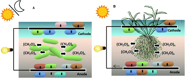 | ||
| Fig. 7 (A) Sediment-type photo-MFC; (B) plant microbial fuel cell.97 | ||
| Plant used | Power density (mW m−2) | Current density (mA m−2) | References |
|---|---|---|---|
| Rice paddy field | 6 | — | 93 |
| Spartina anglica at roof top | 88 | — | 91 |
| Duckweed (Lemna minuta) | 380 ± 19 | 1620 ± 100 | 94 |
| Duckweed (Lemna valdiviana) | — | 226 ± 11 | 92 |
| Rice paddy rhizosphere | 1.3 | — | 88 |
| Glyceria maxima | 12 | — | 95 |
| Grass species Spartina anglica | 679 | 2080 | 87 |
| Spartina anglica | 21 | 31 | 96 |
| Arundinella anomala | 10 | 39 | 96 |
| Arundo donax | No stable electricity production | — | 96 |
Microalgae and some bacteria such as Cyanobacteria90 contribute to increased SOM via photosynthesis97 (Fig. 7-A). This technology is called sediment-type photoMFCs, where electricity generation exhibits an inverse relationship with illumination, because of the negative effect of the oxygen accumulation via photosynthesis.97,98 This problem can be overcome by using color filters or increasing the thickness of the sediment.98
Sediment bed conductivity is the other important factor affecting the efficiency of power generation in SMFCs. Adding conductive materials to sediment may improve the conductivity of the sediment by serving as electron conduits between the bacterial cells and anodes.32,99 Graphite flakes32 and colloidal iron oxyhydroxide99 are such conductive materials that can be used for enhancing the performance of SMFCs.
The operating pH in the sediment bed70 and different pretreatment methods for sediments29 also affect the efficiency of power generation.
6.4. Overlying water
The nature, origin, flow conditions, characteristics, functional activities, total dissolved solids, pH and temperature of water bodies play crucial roles in power generation.51,78 For example stagnant water bodies have shown higher power generation compared with running water bodies.78 But dissolved oxygen (DO) is the most significant factor. Oxygen is utilized as an electron acceptor.63 Therefore DO is another important factor for SMFCs.50,86 Researchers’ findings indicate that different methods can be used for increasing DO in water. These methods are summarized in Table 8.| DO increasing method | References |
|---|---|
| Rotating cathode | 31 and 100 |
| Floating cathode | 36 and 61 |
| Air cathode | 66, 73, 101 and 102 |
| Cold seep sediments | 54 and 103 |
| Algae assisted cathode | 86 |
| Plant rhizosphere | 88 |
| Bio cathode | 8 and 104 |
In rotating cathode technology, rotation of the cathode disks also increases the dissolved oxygen in the overlying water (Fig. 8-C). No external energy input is required when disk drives are rotated by natural water currents.31 In a floating SMFC (Fig. 8-B), the cathode is floated on the water surface, so that a part of its surface is exposed to air. This technology overlaps with the air–cathode method in which the cathode is placed at the air–water interface (Fig. 8-A). On the other hand, algae such as Chlorella vulgarisis fix CO2 during photosynthesis, releasing oxygen as a byproduct86 and saturating water with oxygen.
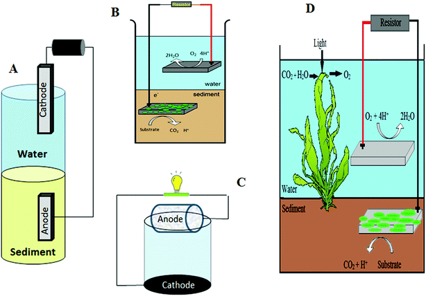 | ||
| Fig. 8 Schematic of (A) an air-cathode; (B) a floating cathode; (C) a rotating cathode technology; and (D) a biocathode. | ||
Part of the produced oxygen in plant-MFCs is released into the rhizosphere by the roots. Hence rhizospheres can act as an oxygen source provided that one cathode is placed in the sediment part of the SMFC.88
DO is also a function of temperature such that it increases with decreasing temperature, leading to an increased power generation efficiency in the cold seep ocean.
6.5. Equipment configuration
Power generation is affected by several additional factors related to SMFC configuration. These factors include electrode spacing, water depth, depth of the embedded anode, the anode chamber, cathode arrangement etc.When the electrode spacing is increased, ohmic losses increase, decreasing the amount of current generated from the SMFC.50 To minimize these ohmic losses, a new type of floating SMFC with a constant inter-electrode spacing can be used.51 Increasing the water and embedded anode depths also contributes to an increase in the electrode spacing,105,106 while increasing the anode depth enhances the internal resistances of SMFCs.107 On the other hand, at different depths of sediment, certain substrates and microorganisms are active, enhancing anode performance at greater depths.107 Therefore, anode embedded depth should be determined locally.
A major challenge in SMFCs is anode passivation.77 Passivation is the inhibition of the dissolution reaction caused by the formation of non-dissolving films. Anode passivation results in lost production capacity, increased power costs, and decreased cathode quality. In 2007, Guzman et al. avoided this problem by using a chambered SMFC design in which the anode is placed in a semi-enclosed chamber that rests securely on the seafloor (Fig. 8).16 By using a one-way check valve, water solely outflows from the underlying sediment into the chamber and not in the opposite direction. This water is nutrient-rich and depleted of oxygen due to oxygen consumption by microbes present within the sediment.16
According to Ohm’s law, an increase in current generation should be observed as decreasing external resistance.78 External resistance may also affect power density, such that the power density increases with external resistance. Therefore, the highest power density and produced current may not be achieved at the same external resistance; so, our ultimate goal is to determine an optimum value of external resistance.
The effects of electrode surface area ratio50 and various electrode arrangements30,44,78,108 have also been investigated in the literature.
7. Scale-up
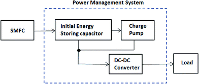
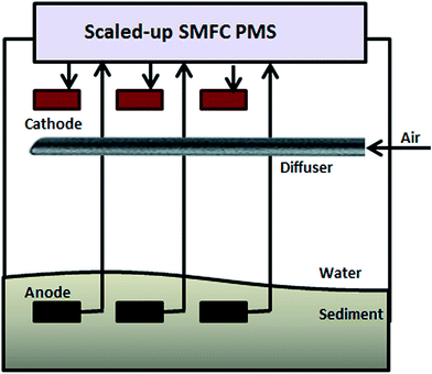
Until now, apart from storing the energy and using it intermittently, there has been no MFC (including SMFCs) capable of producing Watt-level power.109 Power management systems (PMSs) can be used to overcome low power generation issues by cyclic charging and discharging of a capacitor that converts a low potential into a high one.64 A major component of a PMS is shown in Fig. 9. In the recent literature, different PMSs have been developed for SMFCs.30,62,64,65,67,109It is obvious that a scalable technology SMFC that enables Watt-level power generation will be more useful. Two approaches to scale SMFCs up are: (1) connecting multiple MFCs in series; and (2) increasing the surface area of the electrodes equivalent to connecting multiple MFCs in parallel.110–112 The first alternative is impossible because all the electrodes are immersed in the same solution. On the other hand, it is impossible to scale an SMFC up by increasing the surface area of the electrodes due to the resultant sharp decline in current density.109 Indeed, the surface area needs to be increased by almost 100-fold to merely double the power output; this is clearly problematic.110 In 2014, Ewing et al. made it possible to scale-up SMFCs by using smaller-sized individually operated SMFCs connected to a power management system. In this system, the electrodes were electrically isolated (Fig. 10).
8. Summary and future development
In this article, sediment type microbial fuel cells were overviewed including issues such as new materials for use in anodes and cathodes, sediment and overlying water properties, types of equipment configuration etc.It seems that fossil fuels may not supply the increasing energy demand of the future, so it is essential to find sustainable and renewable sources of energy. The results of recent studies suggest that SMFCs will be of practical use in bioenergy production and waste removal from sediments in the future. SMFCs need to provide a higher power output at a lower cost to be considered practically and commercially affordable. In this respect, nano-materials are examples of current research lines. However, to move this technology from laboratory trials to field applications all the challenges discussed in this review need to be further considered before wide application of SMFCs can be realized. In order to further develop SMFC technology, it is suggested to evaluate energy collecting methods, develop PMS and scale-up technologies, and to use cost-effective materials, process monitoring and control, etc.
Until recently, most developed SMFCs were not designed for sediment remediation. For remediation applications, power output is not the major goal. For this issue, simulating sediment bioremediation, in situ bioremediation processes, and environmental, ecological and social considerations require further attention and using a moderate input of external energy (from renewable energy sources) to improve bioremediation must be studied in future. Also, most recent studies have been done on non-complex materials in sediment/soil. So, bioremediation of complex materials in sediments should be considered in the future.
Further, to date most studies have been carried out using laboratory-scale SMFCs. In the near future, investigators will face the new challenge of transitioning SMFCs from the laboratory to aquatic environments; for example, SMFC setup installation in aquatic sediments, passivation of electrode materials by electrochemical deposition, the corrosion of electrode materials and connections, SMFC setup destruction by current flow and fish grazing etc. On the other hand, electrode materials (such as nanomaterials which are used increasingly) and electrochemical reaction effects on the surrounding environment and ecological system must be considered. Challenges in SMFCs will be overcome by the cooperation of different disciplines.
References
- G. Akhmat, K. Zaman, T. Shukui and F. Sajjad, Renewable Sustainable Energy Rev., 2014, 36, 123–134 CrossRef.
- A. Tardast, M. Rahimnejad, G. Najafpour, A. Ghoreyshi, G. C. Premier, G. Bakeri and S.-E. Oh, Fuel, 2014, 117, 697–703 CrossRef CAS.
- M. Rahimnejad, A. A. Ghoreyshi, G. Najafpour and T. Jafary, Appl. Energy, 2011, 88, 3999–4004 CrossRef CAS.
- A. E. Franks and K. P. Nevin, Energies, 2010, 3, 899–919 CrossRef CAS.
- W. R. W. Daud, G. Najafpour and M. Rahimnejad, Iran. J. Energy Environ., 2011, 2, 262–273 Search PubMed.
- M. Rahimnejad, M. Ghasemi, G. D. Najafpour, M. Ismail, A. W. Mohammad, A. A. Ghoreyshi and S. H. A. Hassan, Electrochim. Acta, 2012, 85, 700–706 CrossRef CAS.
- S. Peighambardoust, S. Rowshanzamir and M. Amjadi, Int. J. Hydrogen Energy, 2010, 35, 9349–9384 CrossRef CAS.
- P. Izadi, M. Rahimnejad and A. Ghoreyshi, Biotechnol. Appl. Biochem., 2015, 62, 483–488 CrossRef CAS PubMed.
- M. Rahimnejad, A. Ghoreyshi, G. Najafpour, H. Younesi and M. Shakeri, Int. J. Hydrogen Energy, 2012, 37(7), 5992–6000 CrossRef CAS.
- B. E. Logan, Microbial fuel cell, Wiley, 2008 Search PubMed.
- X. A. Walter, J. Greenman and I. A. Ieropoulos, Algal Res., 2013, 2, 183–187 CrossRef.
- S. Fatemi, A. Ghoreyshi, G. Najafpour and M. Rahimnejad, Iran. J. Energy Environ., 2012, 3, 2079–2115 Search PubMed.
- Y. Yang, G. Sun and M. Xu, J. Chem. Technol. Biotechnol., 2011, 86, 625–632 CrossRef CAS.
- A. Tardast, M. Rahimnejad, G. Najafpour, A. Ghoreyshi, G. C. Premier, G. Bakeri and S.-E. Oh, Fuel, 2014, 117, 697–703 CrossRef CAS.
- M. Ghasemi, W. R. W. Daud, M. Rahimnejad, M. Rezayi, A. Fatemi, Y. Jafari, M. Somalu and A. Manzour, Int. J. Hydrogen Energy, 2013, 38, 9533–9540 CrossRef CAS.
- J. J. Guzman, K. G. Cooke, M. O. Gay, S. E. Radachowsky, P. R. Girguis and M. A. Chiu, Proc. SPIE, 2010, 7666, 68–73 CrossRef.
- N. Mokhtarian, W. Wan Ramli, M. Rahimnejad and G. Najafpour, World Appl. Sci. J., 2012, 18, 559–567 CAS.
- M. Rahimnejad, G. Najafpour, A. Ghoreyshi, M. Shakeri and H. Zare, Int. J. Hydrogen Energy, 2011, 36, 13335–13341 CrossRef CAS.
- M. Rahimnejad, G. Bakeri, G. Najafpour, M. Ghasemi and S.-E. Oh, Biofuel Res. J., 2014, 1, 34–38 CrossRef.
- M. Rahimnejad, G. D. Najafpour, A. A. Ghoreyshi, F. Talebnia, G. C. Premier, G. Bakeri, J. R. Kim and S.-E. Oh, J. Microbiol., 2012, 50, 575–580 CrossRef CAS PubMed.
- M. Rahimnejad, T. Jafary, F. Haghparast, G. D. Najafpour and A. A. Ghoreyshi, Turk. J. Eng. Environ. Sci., 2011, 34, 289–292 Search PubMed.
- M. Rahimnejad, A. Adhami, S. Darvari, A. Zirepour and S.-E. Oh, Alexandria Eng. J., 2015, 54, 745–756 CrossRef.
- M. Rahimnejad, M. Ghasemi, G. Najafpour, A. Ghoreyshi, G. Bakeri, S. K. Hassani Nejad and F. Talebnia, Am. J. Biochem. Biotechnol., 2012, 8, 304–310 CrossRef CAS.
- T.-S. Song, D.-B. Wang, S. Han, X.-y. Wu and C. C. Zhou, Int. J. Hydrogen Energy, 2014, 39, 1056–1062 CrossRef CAS.
- S. W. Hong, H. S. Kim and T. H. Chung, Environ. Pollut., 2010, 158, 185–191 CrossRef CAS PubMed.
- F. Rezaei, T. L. Richard, R. A. Brennan and B. E. Logan, Environ. Sci. Technol., 2007, 41, 4053–4058 CrossRef CAS PubMed.
- W.-W. Li and H.-Q. Yu, Biotechnol. Adv., 2015, 33, 1–12 CrossRef CAS PubMed.
- S.-E. Oh, J. Y. Yoon, A. Gurung and D.-J. Kim, Bioresour. Technol., 2014, 165, 21–26 CrossRef CAS PubMed.
- T.-S. Song and H.-L. Jiang, Bioresour. Technol., 2011, 102, 10465–10470 CrossRef CAS PubMed.
- F. Zhang, L. Tian and Z. He, J. Power Sources, 2011, 196, 9568–9573 CrossRef CAS.
- Z. He, H. Shao and L. T. Angenent, Biosens. Bioelectron., 2007, 22, 3252–3255 CrossRef CAS PubMed.
- M. Lenin Babu and S. Venkata Mohan, Bioresour. Technol., 2012, 110, 206–213 CrossRef CAS PubMed.
- C. E. Reimers, L. M. Tender, S. Fertig and W. Wang, Environ. Sci. Technol., 2000, 35, 192–195 CrossRef.
- Y. Gong, S. E. Radachowsky, M. Wolf, M. E. Nielsen, P. R. Girguis and C. E. Reimers, Environ. Sci. Technol., 2011, 45, 5047–5053 CrossRef CAS PubMed.
- N. J. Sacco, E. L. M. Figuerola, G. Pataccini, M. C. Bonetto, L. Erijman and E. Cortón, Bioresour. Technol., 2012, 126, 328–335 CrossRef CAS PubMed.
- A. Wang, H. Cheng, N. Ren, D. Cui, N. Lin and W. Wu, Front. Environ. Sci. Eng., 2012, 6, 569–574 CrossRef CAS.
- M. C. Potter, Proc. R. Soc. London, Ser. B, 1911, 84, 260–276 CrossRef.
- K. Lewis, Bacteriol. Rev., 1966, 30, 101 CAS.
- R. M. Allen and H. P. Bennetto, Appl. Biochem. Biotechnol., 1993, 39, 27–40 CrossRef.
- B. H. Kim, D. H. Park, P. K. Shin, I. S. Chang and H. J. Kim, U.S. Pat. 5976719, 1999.
- H. Kim, M. Hyun, I. Chang and B. H. Kim, J. Microbiol. Biotechnol., 1999, 9, 365–367 CAS.
- T.-S. Song, W.-M. Tan, X.-Y. Wu and C. C. Zhou, J. Chem. Technol. Biotechnol., 2012, 87, 1436–1440 CrossRef CAS.
- T.-S. Song, Z.-S. Yan, Z.-W. Zhao and H.-L. Jiang, J. Chem. Technol. Biotechnol., 2010, 85, 1489–1493 CAS.
- T.-S. Song, Z.-S. Yan, Z.-W. Zhao and H.-L. Jiang, Bioprocess Biosyst. Eng., 2011, 34, 621–627 CrossRef CAS PubMed.
- C.-C. Fu, T.-C. Hung, W.-T. Wu, T.-C. Wen and C.-H. Su, Biochem. Eng. J., 2010, 52, 175–180 CrossRef CAS.
- Y. Fu, Q. Xu, X. Zai, Y. Liu and Z. Lu, Appl. Surf. Sci., 2014, 289, 472–477 CrossRef CAS.
- Y. Fu, J. Yu, Y. Zhang and Y. Meng, Appl. Surf. Sci., 2014, 317, 84–89 CrossRef CAS.
- Y. Fu, Z. Zhao, J. Liu, K. Li, Q. Xu and S. Zhang, Sci. China: Chem., 2011, 54, 844–849 CrossRef CAS.
- S. Hong, I. Chang, Y. Choi, B. Kim and T. Chung, Bioprocess Biosyst. Eng., 2009, 32, 389–395 CrossRef CAS PubMed.
- S. W. Hong, I. S. Chang, Y. S. Choi and T. H. Chung, Bioresour. Technol., 2009, 100, 3029–3035 CrossRef CAS PubMed.
- S.-W. Hong, H.-J. Kim, Y.-S. Choi and T.-H. Chung, Bull. Korean Chem. Soc., 2008, 29, 2189–2194 CrossRef CAS.
- D. A. Lowy, L. M. Tender, J. G. Zeikus, D. H. Park and D. R. Lovley, Biosens. Bioelectron., 2006, 21, 2058–2063 CrossRef CAS PubMed.
- L. M. Tender, S. A. Gray, E. Groveman, D. A. Lowy, P. Kauffman, J. Melhado, R. C. Tyce, D. Flynn, R. Petrecca and J. Dobarro, J. Power Sources, 2008, 179, 571–575 CrossRef CAS.
- M. E. Nielsen, C. E. Reimers, H. K. White, S. Sharma and P. R. Girguis, Energy Environ. Sci., 2008, 1, 584–593 CAS.
- K. Scott, I. Cotlarciuc, D. Hall, J. B. Lakeman and D. Browning, J. Appl. Electrochem., 2008, 38, 1313–1319 CrossRef CAS.
- M. Rahimnejad, N. Mokhtarian, G. Najafpour, A. Ghoreyshi and W. Dahud, World Appl. Sci. J., 2009, 6, 1585–1588 CAS.
- M. Ghasemi, W. R. W. Daud, S. H. Hassan, S.-E. Oh, M. Ismail, M. Rahimnejad and J. M. Jahim, J. Alloys Compd., 2013, 580, 245–255 CrossRef CAS.
- G. Najafpour, M. Rahimnejad, N. Mokhtarian, W. R. W. Daud and A. Ghoreyshi, World Appl. Sci. J., 2010, 8, 1–5 CAS.
- D. A. Lowy and L. M. Tender, J. Power Sources, 2008, 185, 70–75 CrossRef CAS.
- D. R. Lovley, Nat. Rev. Microbiol., 2006, 4, 497–508 CrossRef CAS PubMed.
- Y. Huang, Z. He, J. Kan, A. K. Manohar, K. H. Nealson and F. Mansfeld, Bioresour. Technol., 2012, 114, 308–313 CrossRef CAS PubMed.
- Y. R. J. Thomas, M. Picot, A. Carer, O. Berder, O. Sentieys and F. Barrière, J. Power Sources, 2013, 241, 703–708 CrossRef CAS.
- R. Renslow, C. Donovan, M. Shim, J. Babauta, S. Nannapaneni, J. Schenk and H. Beyenal, Phys. Chem. Chem. Phys., 2011, 13, 21573–21584 RSC.
- C. Donovan, A. Dewan, D. Heo, Z. Lewandowski and H. Beyenal, J. Power Sources, 2013, 233, 79–85 CrossRef CAS.
- C. Donovan, A. Dewan, D. Heo and H. Beyenal, Environ. Sci. Technol., 2008, 42, 8591–8596 CrossRef CAS PubMed.
- D. Majumder, J. P. Maity, C.-Y. Chen, C.-C. Chen, T.-C. Yang, Y.-F. Chang, D.-W. Hsu and H.-R. Chen, Int. J. Hydrogen Energy, 2014, 39, 21215–21222 CrossRef CAS.
- C. Donovan, A. Dewan, H. Peng, D. Heo and H. Beyenal, J. Power Sources, 2011, 196, 1171–1177 CrossRef CAS.
- M. E. Nielsen, Doctoral, Oregon state university, 2008.
- Z. Yan, N. Song, H. Cai, J.-H. Tay and H. Jiang, J. Hazard. Mater., 2012, 199, 217–225 CrossRef PubMed.
- T. K. Sajana, M. M. Ghangrekar and A. Mitra, Aquacultural Engineering, 2014, 61, 17–26 CrossRef.
- D.-Y. Huang, S.-G. Zhou, Q. Chen, B. Zhao, Y. Yuan and L. Zhuang, Chem. Eng. J., 2011, 172, 647–653 CrossRef CAS.
- N. Touch, T. Hibino, Y. Nagatsu and K. Tachiuchi, Bioresour. Technol., 2014, 158, 225–230 CrossRef CAS PubMed.
- J. M. Morris and S. Jin, J. Hazard. Mater., 2012, 213–214, 474–477 CrossRef CAS PubMed.
- T. K. Sajana, M. M. Ghangrekar and A. Mitra, Aquacultural Engineering, 2013, 57, 101–107 CrossRef.
- Y. Zhang and I. Angelidaki, Water Res., 2012, 46, 6445–6453 CrossRef CAS PubMed.
- T.-S. Song, H.-Y. Cai, Z.-S. Yan, Z.-W. Zhao and H.-L. Jiang, Bioresour. Technol., 2012, 108, 68–75 CrossRef CAS PubMed.
- M. E. Nielsen, C. E. Reimers and H. A. Stecher, Environ. Sci. Technol., 2007, 41, 7895–7900 CrossRef CAS PubMed.
- S. V. Mohan, S. Srikanth, S. V. Raghuvulu, G. Mohanakrishna, A. K. Kumar and P. N. Sarma, Bioresour. Technol., 2009, 100, 2240–2246 CrossRef CAS PubMed.
- F. Y.-B. L. Zhi-Kai, X. Qian, L. Yuan-Yuan and Z. Ye-Long, J. Inorg. Mater., 2013, 28, 278–282 CrossRef.
- L. D. Schamphelaire, P. Boeckx and W. Verstraete, Appl. Microbiol. Biotechnol., 2010, 87, 1675–1687 CrossRef PubMed.
- C. Dumas, A. Mollica, D. Féron, R. Basseguy, L. Etcheverry and A. Bergel, Bioresour. Technol., 2008, 99, 8887–8894 CrossRef CAS PubMed.
- C. Dumas, A. Mollica, D. Féron, R. Basséguy, L. Etcheverry and A. Bergel, Electrochim. Acta, 2007, 53, 468–473 CrossRef CAS.
- L. Zhi-Kai, F. Yu-Bin, X. Qian, L. Yuan-Yuan and Z. Ye-Long, J. Inorg. Mater., 2013, 28, 278–282 CrossRef.
- Y. Ren, D. Pan, X. Li, F. Fu, Y. Zhao and X. Wang, J. Chem. Technol. Biotechnol., 2013, 88, 1946–1950 CrossRef CAS.
- K. Scott, I. Cotlarciuc, I. Head, K. P. Katuri, D. Hall, J. B. Lakeman and D. Browning, J. Chem. Technol. Biotechnol., 2008, 83, 1244–1254 CrossRef CAS.
- D.-B. Wang, T.-S. Song, T. Guo, Q. Zeng and J. Xie, Int. J. Hydrogen Energy, 2014, 39, 13224–13230 CrossRef CAS.
- K. Wetser, E. Sudirjo, C. J. N. Buisman and D. P. B. T. B. Strik, Appl. Energy, 2015, 137, 151–157 CrossRef CAS.
- Z. Chen, Y.-C. Huang, J.-H. Liang, F. Zhao and Y.-G. Zhu, Bioresour. Technol., 2012, 108, 55–59 CrossRef CAS PubMed.
- T. K. Sajana, M. M. Ghangrekar and A. Mitra, Bioresour. Technol., 2014, 155, 84–90 CrossRef CAS PubMed.
- J. Zhao, X.-F. Li, Y.-P. Ren, X.-H. Wang and C. Jian, J. Chem. Technol. Biotechnol., 2012, 87, 1567–1573 CrossRef CAS.
- M. Helder, D. P. B. T. B. Strik, R. A. Timmers, S. M. T. Raes, H. V. M. Hamelers and C. J. N. Buisman, Biomass Bioenergy, 2013, 51, 1–7 CrossRef CAS.
- Y. Hubenova and M. Mitov, Bioelectrochemistry, 2015, 106, 226–231 CrossRef CAS PubMed.
- N. Kaku, N. Yonezawa, Y. Kodama and K. Watanabe, Appl. Microbiol. Biotechnol., 2008, 79, 43–49 CrossRef CAS PubMed.
- Y. Hubenova and M. Mitov, Bioelectrochemistry, 2012, 87, 185–191 CrossRef CAS PubMed.
- R. A. Timmers, D. P. B. T. B. Strik, H. V. M. Hamelers and C. J. N. Buisman, Biomass Bioenergy, 2013, 51, 60–67 CrossRef CAS.
- M. Helder, D. P. B. T. B. Strik, H. V. M. Hamelers, A. J. Kuhn, C. Blok and C. J. N. Buisman, Bioresour. Technol., 2010, 101, 3541–3547 CrossRef CAS PubMed.
- M. Rosenbaum, Z. He and L. T. Angenent, Curr. Opin. Biotechnol., 2010, 21, 259–264 CrossRef CAS PubMed.
- Z. He, J. Kan, F. Mansfeld, L. T. Angenent and K. H. Nealson, Environ. Sci. Technol., 2009, 43, 1648–1654 CrossRef CAS PubMed.
- Y.-L. Zhou, Y. Yang, M. Chen, Z.-W. Zhao and H.-L. Jiang, Bioresour. Technol., 2014, 159, 232–239 CrossRef CAS PubMed.
- D. Suor, J. Ma, Z. Wang, Y. Li, J. Tang and Z. Wu, Chem. Eng. J., 2014, 248, 415–421 CrossRef CAS.
- Z. Chen, Y.-C. Huang, J.-H. Liang, F. Zhao and Y.-G. Zhu, Bioresour. Technol., 2012, 108, 55–59 CrossRef CAS PubMed.
- Y. Yuan, S. Zhou and L. Zhuang, J. Soils Sediments, 2010, 10, 1427–1433 CrossRef CAS.
- C. E. Reimers, P. Girguis, H. A. Stecher, L. M. Tender, N. Ryckelynck and P. Whaling, Geobiology, 2006, 4, 123–136 CrossRef CAS.
- J. M. Pisciotta, Z. Zaybak, D. F. Call, J.-Y. Nam and B. E. Logan, Appl. Environ. Microbiol., 2012, 78, 5212–5219 CrossRef CAS PubMed.
- H. Deng, Y. C. Wu, F. Zhang, Z. C. Huang, Z. Chen, H. J. Xu and F. Zhao, Pedosphere, 2014, 24, 330–338 CrossRef CAS.
- B. Erable, R. Lacroix, L. Etcheverry, D. Féron, M. L. Delia and A. Bergel, Bioresour. Technol., 2013, 142, 510–516 CrossRef CAS PubMed.
- J. An, B. Kim, J. Nam, H. Y. Ng and I. S. Chang, Bioresour. Technol., 2013, 127, 138–142 CrossRef CAS PubMed.
- U. Karra, G. Huang, R. Umaz, C. Tenaglier, L. Wang and B. Li, Bioresour. Technol., 2013, 144, 477–484 CrossRef CAS PubMed.
- T. Ewing, P. T. Ha, J. T. Babauta, N. T. Tang, D. Heo and H. Beyenal, J. Power Sources, 2014, 272, 311–319 CrossRef CAS.
- A. Dewan, H. Beyenal and Z. Lewandowski, Environ. Sci. Technol., 2008, 42, 7643–7648 CrossRef CAS PubMed.
- M. Rahimnejad, G. Nnajafpour and Z. Najafgholi, Journal of RenewableEnergy and Environment, 2015, 2, 49–55 Search PubMed.
- M. Rahimnejad and Z. Najafgholi, Korean J. Chem. Eng., DOI:10.1007/s11814-015-0123-x.
| This journal is © The Royal Society of Chemistry 2015 |


