DOI:
10.1039/C5RA15235F
(Paper)
RSC Adv., 2015,
5, 89771-89776
Conversion of straw to nitrogen doped carbon for efficient oxygen reduction catalysts in microbial fuel cells†
Received
31st July 2015
, Accepted 16th October 2015
First published on 16th October 2015
Abstract
The exploration of highly-efficient and low-cost oxygen reduction reaction (ORR) catalysts was still a major task for microbial fuel cells (MFCs). Herein, we report the conversion of cheap and widely available biomass to nitrogen-doped carbon (NC) for highly-efficient ORR catalysts in air-cathode MFCs. The NC was prepared from rice straw through a three-step process, including hydrothermal carbonization, freeze drying and heat-treatment in NH3. The NC had a high nitrogen content of 5.57 at% and showed outstanding catalytic activity for ORR. The MFC based on the NC generated a high maximum power density of 2300 mW m−2, which was much higher than that of the Pt/C.
1. Introduction
A microbial fuel cell (MFC) is a novel technology that uses electroactive bacteria to convert chemical energy into electric energy. It could use wastewater as fuel, thus it was a “green” energy resource and showed great potential in wastewater treatment.1,2 The cost and performance of electrode materials was still one of the obstacles that restricted the practical application of the MFCs. Oxygen was one of the most sustainable electron acceptor for cathode of MFC due to its abundance. Owing to the inherently poor efficiency of the ORR, catalyst was usually required. Currently, platinum and its alloys were still the most efficient catalysts for ORR,3 however, their practical applications were greatly restricted due to their scarcity. Therefore, tremendous efforts have been made to explore alternatives to Pt. As new contenders, transition metal compounds such as transition metal macrocyclic compounds4–6 and transition metal oxides,7–9 have been proved to be high efficient ORR catalysts for MFCs. However, these metal-based catalysts still remained disadvantages, such as pollution caused by metal residues.10–12 Since Gong and coworkers found that metal-free nitrogen-doped carbon nanotube array was a high electrocatalytic activity ORR catalyst,13 the NCs were also introduced to the cathode of MFC and had been demonstrated outstanding catalytic activity.14,15 But, these catalysts were based on the carbon nanomaterials and not available readily, which weighted against for the scale-up of MFC. Activated carbons (ACs) were also widely used as ORR catalyst in the cathode of MFCs16,17 due to the characteristics of cost-effective, long term stability and efficiency.18–21 However, the catalytic activity of the pristine AC was too low and modification was usually needed. Great efforts had been devoted to improve the performance of AC through nitrogen doping22,23 but it was still undesirable. One of the main reason was the nitrogen content was too low (below 2%).24 Therefore, the exploration of low-cost NC with appropriate nitrogen content for ORR catalysts in MFCs remains a great challenge.
Recently, the conversion of waste biomass to “green” carbon through hydrothermal carbonization process have attracted tremendous attention, because biomass was highly available25 and hydrothermal carbonization process had intrinsic advantages such as benign environment and economic cost.26,27 Rice straw was one of the most abundant biomass in the world. It was reported that the production of straw was about 731 million tons each year all over the world.28 Due to the lack of effective utilization, most of them were discarded or burnt in open environment, which leaded to a great extent of resource waste. Therefore, it would be of great significance if the waste straw could be used as raw material to prepare low-cost and high efficient NC for the “green” MFC.
In this paper, NC was prepared from rice straw through a three-step process, including hydrothermal carbonization, freeze drying then heat-treatment in NH3, and used as a low-cost and high performance ORR catalyst for MFC. The NC had high nitrogen content of 5.57 at% and exhibited outstanding electrocatalytic activity. The MFC based on the NC generated maximum power density of 2300 mW m−2, which was much higher than that of MFC using Pt/C.
2. Methods
2.1. Catalyst preparation
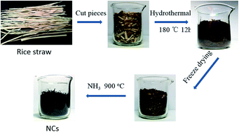
The preparation process of the NCs was illustrated in Scheme 1, which was a slightly modified process following previous report.29 The rice straw (obtained from Qingshan, Nanchang) was cut into small pieces and washed by distilled water to remove the impurities and then dried at 80 °C. Typically, 3.0 g straw and 25 mL distilled water were poured into a 50 ml Teflon vessel. Then the autoclave was sealed and heated at 180 °C for 12 h, and then allowed to cool down naturally. The black carbonaceous hydrogel was filtered and washed with distilled water for several times and freeze dried for 24 h. Subsequently, the freeze-dried carbonaceous hydrogel was heated in a quartz tube at 900 °C for 2 h with a heating rate of 5 °C min−1 under NH3 atmosphere. After carbonization, the catalysts were leached with 1 M HCl and 20% HF, respectively, to remove the impurities. Then they were centrifuged and washed with distilled water for several times, and dried overnight. The resulted products were denoted as H–NC-T (T represents the thermal treatment temperature). Samples of H–NC-800, H–NC-900 and H–NC-1000 were prepared respectively. For comparison, H–C-900 without nitrogen doping was prepared at 900 °C under the same condition except for the argon atmosphere.
 |
| Scheme 1 Fabrication process of the NCs from rice straw. | |
2.2. Electrode preparation and electrochemical test
Cyclic voltammetry (CV) measurement was used to evaluate the electrocatalytic activity of the ORR catalysts. In a typical procedure, a glassy carbon (GC, ∅ = 3 mm) electrode was firstly polished on a chamois leather with 1 μm and then 0.05 μm alumina powder, then ultrasonic treated with ethanol and deionized water for 5 min and dried. Catalysts (1 mg), Nafion (25 μL) were dispersed in deionized water (250 μL) to form a homogeneous ink in the assistance of ultrasonic. Then 5 μL catalyst ink was pipetted onto the electrode surface, and dried naturally at room temperature.
Rotating ring disk electrode (RRDE, disk ∅ = 5.61 mm, ring inner ∅ = 6.25 mm, and ring outer ∅ = 7.92 mm) was used for linear scanning voltammetry (LSV) test to verify the electrocatalytic pathways of the ORR. The loading of catalyst onto the RRDE was similar to GC, except that 15 μL catalyst ink was used. The RRDE measurement was carried out by a potentiostat (Bio-logic, VMP3) equipped with a rotating controller (Pine Research Instrumentation) in O2-saturated 50 mM PBS solution (pH = 7.0) at room temperature. Pt wire and Ag/AgCl (saturated KCl) were used as counter and reference electrodes, respectively. The scan rate was 10 mV s−1. The polarization potential of the Pt ring electrode was 0.5 V versus Ag/AgCl. The H2O2 yield and electron transfer numbers (n) were calculated according to the following equations:
|
 | (1) |
|
 | (2) |
where
ID is the disk current,
IR is the ring current.
N refers to the collection efficiency of Pt ring, and 0.4 is determined by the reduction of K
3Fe[CN]
6.
2.3. Characterization
The morphologies of the NCs were observed by scanning electron microscope (SEM, TESCAN Vega3) and transmission electron microscope (TEM, JSM-2100). The element analysis was conducted with X-ray photoelectron spectroscopy (XPS, PHI Quantera SXM™). The nitrogen adsorption–desorption isotherms were measured at −197 °C using a Micromeritics ASAP 2020 apparatus. The Raman spectra were recorded on a LabRAM Aramis (Horiba Jobin Yvon S.A.S) with a 633 nm wavelength laser.
2.4. MFCs construction and operation
Single-chamber air-cathode MFC architecture was used to measure the performance of the ORR catalyst in the MFC.30 Anodes were heating treated (450 °C for 30 min) graphite fiber brushes. The air-cathodes were fabricated by rolling method following previous report31 using polyfluortetraethylene (PTFE) as binder. The mass ratio of NC/PTFE was controlled to be about 4/1, the loading of catalyst was controlled to be about 20 mg cm−2. For comparison, the air-cathode with Pt/C catalyst was also prepared by the rolling method with the Pt loading of 0.5 mg cm−2.
LSV measurements of the air-cathode were carried out in a conventional three-electrode system equipped with a graphite plate counter electrode and an Ag/AgCl reference electrode. This system was controlled by CHI660D workstation (CH Instruments) at a scan rate of 1 mV s−1 with a voltage range from +0.3 to −0.3 V. All the LSV measurements were conducted in 50 mM PBS solution (pH = 7.0) at 35 °C.
To protect the air-cathode from bio-fouling, a layer of poly vinyl alcohol (PVA) hydrogel was coated onto the catalytic layer of the air-cathode. The PVA hydrogel was prepared by direct freezing/thawing of a 10 wt% PVA aqueous solution, following one of our previous work.32 All MFCs were inoculated with effluent from another MFC (initially inoculated with wastewater from local wastewater treatment plant) operated for over 6 months. Each reactor was operated at 35 °C and fed with a medium containing acetate (1.0 g L−1), vitamin solution (12.5 mL L−1), trace element solution (12.5 mL L−1) in 50 mM phosphate buffer solution (PBS pH 7.0; 10.9233 g L−1 Na2HPO4·12H2O, 3.042 g L−1 NaH2PO4·2H2O, 0.31 g L−1 NH4Cl, 0.13 g L−1 KCl). The date collection system (HIOKI LR8431-30) was used to monitor the cell voltage every minute. Polarization and power density curves were obtained by varying external circuit resistance with each resistor used for a full batch cycle. The power density and current density were normalized to the projected area of the air-cathode (7 cm2). Each result was repeated at least three measurements.
3. Results and discussion
3.1. Preparation and characterization of NCs
A kind of sustainable and widely available biomass, rice straw, was used as precursor to prepare the NCs through a three-step process, including hydrothermal carbonization, freezing-drying and doping of nitrogen under NH3 atmosphere, as shown in Scheme 1. The hydrothermal carbonization was one of popularly used method to prepare porous carbon materials from biomass.25 The hydrothermal process could greatly improve the yield of the NC catalyst. As illustrated in Table 1, the final catalyst yield of the H–NC-900 with hydrothermal process was about 6.7%. While direct carbonization of the rice straw in NH3 without hydrothermal step, no carbon materials were obtained. It had been reported that the hydrothermal carbonization is an exothermal process that lowers both the oxygen and hydrogen content of the feed mainly by dehydration and decarboxylation, and facilitate the formation of carbon microcrystals which was not easy to be etched by the NH3 in the following N doping process.33 Therefore, the hydrothermal carbonization was an essential process for the large-scale preparation of NCs from biomass.
Table 1 Catalysts characteristics and textural parameters
Samples |
Catalyst yield (%) |
Elemental analysis (at%) |
SBET (m2 g−1) |
C |
N |
O |
H–NC-800 |
10.34 |
87.14 |
7.65 |
5.21 |
494.1 |
H–NC-900 |
6.7 |
88.5 |
5.57 |
5.93 |
349.6 |
H–C-900 |
17.21 |
93.46 |
1.12 |
5.42 |
98.9 |
H–NC-1000 |
4.82 |
92.55 |
3.32 |
4.13 |
269.6 |
The heat-treatment of the hydrothermal carbon in NH3 atmosphere at higher temperature was an effective method to dope N element to the carbon materials. As shown in Fig. 1A and Table 1, the XPS analysis results showed that the carbons derived from the rice straw contained C, O and N. The content of N in the H–C-900 prepared without doping of N element was only 1.12 at%, which was mainly from the nutrient element in the rice straw precursor. After the post treatment in NH3, the content of N in the NCs increased greatly, e.g. the H–NC-900 contained a much higher N element of 5.57 at%. The content of N decreased with increasing of treatment temperature, which in accordance to the previous reports.34,35 As shown in Fig. 1B, the N1s high resolution spectrum of H–NC-900 could be fitted into four main peaks located at 398.4, 399.8, 400.9 and 402.5 eV, corresponding to the pyridinic, pyrrolic, graphitic and oxidized pyridinic N, respectively.36,37 The high-resolution N1s spectra of other samples were also presented (Fig. S1†). It had been reported that the introduction of N broke the electroneutralitic sp2-hybridized carbon atoms, creating charged sites that favored O2 adsorption.38
 |
| Fig. 1 (A) Survey XPS spectra of NCs and (B) high-resolution N1s spectra of H–NC-900. | |
The heat treatment of hydrothermal carbon in NH3 not only brought higher content of N to the NCs, but also resulted in higher specific surface area due to the etching of carbon by the NH3. The adsorption–desorption analysis in Fig. S2† revealed that the H–NC-900 and the H–C-900 exhibited a micro- and mesoporous characteristics. The high resolution TEM images in Fig. S3† confirmed the micro- and mesoporous characteristics of the H–NC-900. Moreover, the TEM image and Raman spectroscopy (Fig. S4†) revealed that the H–NC-900 catalyst consisted of perturbed graphitic layers and disordered carbon. The H–NC-900 possessed a high specific surface area of 349.6 m2 g−1 (Table 1), which was much higher than that of the H–C-900 (<100 m2 g−1). During the process of post-treatment in NH3 (temperature ≥ 800 °C), there exists two carbon phases: graphitic crystallite and amorphous carbon. The amorphous carbon would be etched preferentially and lead to internal micro- and mesoporous network simultaneously.39–41 As shown in Fig. S2B and D,† the pore volume in the H–NC-900 was much higher than that in the H–C-900, thus resulted in a high specific surface area. It was said that the micro- and mesopores were very essential for the formation of active sites, and thus would bring superior ORR performance.39
3.2. Electrocatalytic activity of NCs
The RRDE measurement curves of H–NC-800, H–NC-900, H–NC-1000, 20 wt% Pt/C and H–C-900 were shown in Fig. 2A. The H–NC-900 showed an onset potential of about +0.22 V, which extremely approached the 20 wt% Pt/C and also more positive than most of the reported ORR catalysts summarized in Table S1.† By contrast, the H–NC-800 and H–NC-1000 displayed lower disc current density and onset potential. The ring current was also monitored accurately to measure the yield of peroxide species (H2O2).42 As shown in Fig. 2B, the H–NC-900 had a low H2O2 yield of below 7%. The electron transfer number (n) in the H–NC-900 was 3.86, suggesting that it favored a 4-electron process which similar to 20 wt% Pt/C (n = 3.97) and also higher than most of the catalysts in Table S1.† However, the H2O2 yield of the H–C-900 reached up to 34%, corresponding to an electron transfer number of 3.30, suggesting hybrid path of 4-electron and 2-electron.
 |
| Fig. 2 (A) LSV curves of 20 wt% Pt/C, H–NC-900, H–NC-800, H–NC-1000 and H–C-900 loaded on RRDE at 1600 rpm in O2-saturated 50 mM PBS. The scan rate was 10 mV s−1. (B) Percentage of peroxide (solid line) and the electron transfer number (n) (dotted line) of 20 wt% Pt/C, H–NC-900 and H–C-900 at various potentials. | |
Compared to other NCs, the H–NC-900 exhibited the best catalytic activity. It was well-known that the temperature is to balance the nitrogen content, specific surface area and graphitic structure in the NCs, which was essential for the density of catalytic sites and electron transfer rate. Though the H–NC-800 prepared at lower temperature had higher nitrogen content and specific area, it contained low degree of graphitic carbon and thus led to low rate of electron transfer rate. Higher temperature would led to the low nitrogen content and specific surface area, thus resulted in low density of active sites in the H–NC-1000. The reasons for the excellent catalytic activity of the H–NC-900 are that, in one aspect, the H–NC-900 had a reasonable nitrogen content of 5.57 at%. Moreover, most of the N was dominated by the pyridinic and pyrrolic states which contributed to the ORR catalytic activity;43–45 meanwhile, it has high specific surface area of 349.6 m2 g−1, which was caused by the large amount of micro- and mesopores, thus resulted a high density of active nitrogen doping sites exposure to the catalytic reaction. In another aspect, based on the TEM and Raman spectroscopy results, the H–NC-900 contained a high degree of graphitic carbon structure which ensured a high rate electron transfer during catalytic reaction.
3.3. MFCs performance
To assess the practical performance of the NC catalysts in MFCs, air-cathodes were prepared by rolling method. As shown in Fig. 3A, all the air-cathodes with NC catalyst displayed higher current response than that of carbon H–C-900. Among these air-cathodes with NC ORR catalysts, the H–NC-900 displayed the highest current density, which even higher than the air-cathode of Pt/C (0.5 mg cm−2). These results indicated that the H–NC-900 showed outstanding performance when using as ORR catalyst in the air-cathode of MFCs. As shown in Fig. 3B, the air-cathode with H–NC-900 catalyst presented a stable voltage of 0.653 V when loading an external resistance of 1000 Ω, which was much higher than that of the air-cathode with H–C-900 catalyst (0.475 V). It was also observed that the air-cathode with Pt/C generated a voltage of 0.603 V under the premise of comparable. The performance of the air-cathodes of H–NC-800 and H–NC-1000 were also tested, they generated a steady output of 0.631 V and 0.582 V for more than 180 h, respectively (Fig. 3B), demonstrating a good electrocatalytic stability.
 |
| Fig. 3 (A) LSV curves of air-cathode with different ORR catalysts in 50 mM PBS with the scan rate of 1 mV s−1. (B) V–t curves of air-cathode with different ORR catalysts at 1000 Ω. | |
According to Fig. 4A, the power density arranged in this order: H–C-900 (992 mW m−2) < H–NC-1000 (1200 mW m−2) < Pt/C (1634 mW m−2) < H–NC-800 (2000 mW m−2) < H–NC-900 (2300 mW m−2). The air-cathode with H–NC-900 presented the best MFC performance. It should be noted that the air-cathode with Pt/C (0.5 mg cm−2) generated a power density of 1634 mW m−2, which was almost the same as the previous report.46 As shown in Fig. 4B, the anode potentials were almost the same, indicating that the differences of power density were caused by the catalytic efficiency of the ORR catalyst in the air-cathode. Fig. 4C showed air-cathode of H–NC-900 with an open circuit voltage of 0.782 V, which was also higher than that of air-cathode with Pt (0.728 V). These results further confirmed that the H–NC-900 was a high-efficient ORR catalyst for MFC.
 |
| Fig. 4 (A) Power density curves of MFCs, (B) anode and cathode potential of the MFCs and (C) polarization curves of MFCs based on the air-cathodes with different catalysts. | |
4. Conclusions
NCs were successfully synthesized from rice straw through a three-step process, including hydrothermal carbonization, freeze drying and doping of nitrogen in NH3, and exhibited outstanding electrochemical activity for ORR in the air-cathode of MFCs. The hydrothermal treatment was a crucial process which greatly increased the catalyst yield and promoted the N-doping in the NCs. The air-cathode using the NC catalyst generated a high power density of 2300 mW m−2, which was higher than that of Pt/C. The excellent performance of the NCs could be attributed to the efficient N-doping and the large surface area. This paper provided a simple, feasible and scalable method to convert the waste biomass to the efficient ORR catalyst.
Acknowledgements
This research was supported by the National Natural Science Foundation of China (51202096, 21464008), the Science and Technology Foundation (20121BBE50024), the Natural Science Foundation of Jiangxi Province (20143ACB21015) and innovation funds of postgraduate (YJS2014055).
References
- B. E. Logan and K. Rabaey, Science, 2012, 337, 686–690 CrossRef CAS PubMed.
- B. E. Logan, B. Hamelers, R. Rozendal, U. Schröder, J. Keller, S. Freguia, P. Aelterman, W. Verstraete and K. Rabaey, Environ. Sci. Technol., 2006, 40, 5181–5192 CrossRef CAS.
- Z. Wei, S. Zhang, Z. Tang and H. Guo, J. Appl. Electrochem., 2000, 30, 723–725 CrossRef CAS.
- S. Cheng, H. Liu and B. E. Logan, Environ. Sci. Technol., 2006, 40, 364–369 CrossRef CAS.
- F. Zhao, F. Harnisch, U. Schröder, F. Scholz, P. Bogdanoff and I. Herrmann, Electrochem. Commun., 2005, 7, 1405–1410 CrossRef CAS PubMed.
- L. Deng, M. Zhou, C. Liu, L. Liu, C. Liu and S. Dong, Talanta, 2010, 81, 444–448 CrossRef CAS PubMed.
- I. Roche, K. Katuri and K. Scott, J. Appl. Electrochem., 2010, 40, 13–21 CrossRef CAS.
- X. W. Liu, X. F. Sun, Y. X. Huang, G. P. Sheng, K. Zhou, R. J. Zeng, F. Dong, S. G. Wang, A. W. Xu and Z. H. Tong, Water Res., 2010, 44, 5298–5305 CrossRef CAS PubMed.
- E. Martin, B. Tartakovsky and O. Savadogo, Electrochim. Acta, 2011, 58, 58–66 CrossRef CAS PubMed.
- Y. Liang, Y. Li, H. Wang, J. Zhou, J. Wang, T. Regier and H. Dai, Nat. Mater., 2011, 10, 780–786 CrossRef CAS PubMed.
- D. Yu, E. Nagelli, F. Du and L. Dai, J. Phys. Chem. Lett., 2010, 1, 2165–2173 CrossRef CAS.
- H. Tang, H. Yin, J. Wang, N. Yang, D. Wang and Z. Tang, Angew. Chem., Int. Ed., 2013, 125, 5695–5699 CrossRef PubMed.
- K. Gong, F. Du, Z. Xia, M. Durstock and L. Dai, Science, 2009, 323, 760–764 CrossRef CAS PubMed.
- L. Feng, Y. Yan, Y. Chen and L. Wang, Energy Environ. Sci., 2011, 4, 1892–1899 CAS.
- S. Li, Y. Hu, Q. Xu, J. Sun, B. Hou and Y. Zhang, J. Power Sources, 2012, 213, 265–269 CrossRef CAS PubMed.
- F. Zhang, S. Cheng, D. Pant, G. V. Bogaert and B. E. Logan, Electrochem. Commun., 2009, 11, 2177–2179 CrossRef CAS PubMed.
- H. Dong, H. Yu, X. Wang, Q. Zhou and J. Feng, Water Res., 2012, 46, 5777–5787 CrossRef CAS PubMed.
- B. Wei, J. C. Tokash, G. Chen, M. A. Hickner and B. E. Logan, RSC Adv., 2012, 2, 12751–12758 RSC.
- H. R. Luckarift, S. R. Sizemore, K. E. Farrington, J. Roy, C. Lau, P. B. Atanassov and G. R. Johnson, ACS Appl. Mater. Interfaces, 2012, 4, 2082–2087 CAS.
- G. Chen, B. Wei, Y. Luo, B. E. Logan and M. A. Hickner, ACS Appl. Mater. Interfaces, 2012, 4, 6454–6457 CAS.
- X. Xia, F. Zhang, X. Zhang, P. Liang, X. Huang and B. E. Logan, ACS Appl. Mater. Interfaces, 2013, 5, 7862–7866 CAS.
- X. Shi, Y. Feng, X. Wang, H. Lee, J. Liu, Y. Qu, W. He, S. S. Kumar and N. Ren, Bioresour. Technol., 2012, 108, 89–93 CrossRef CAS PubMed.
- V. J. Watson, C. N. Delgado and B. E. Logan, J. Power Sources, 2013, 242, 756–761 CrossRef CAS PubMed.
- B. Zhang, Z. Wen, S. Ci, S. Mao, J. Chen and Z. He, ACS Appl. Mater. Interfaces, 2014, 6, 7464–7470 CAS.
- M. M. Titirici and M. Antonietti, Chem. Soc. Rev., 2010, 39, 103–116 RSC.
- D. R. Dodds and R. A. Gross, Science, 2007, 318, 1250–1251 CrossRef CAS PubMed.
- A. A. Peterson, F. Vogel, R. P. Lachance, M. Fröling, M. J. Antal Jr and J. W. Tester, Energy Environ. Sci., 2008, 1, 32–65 CAS.
- P. Binod, R. Sindhu, R. R. Singhania, S. Vikram, L. Devi, S. Nagalakshmi, N. Kurien, R. K. Sukumaran and A. Pandey, Bioresour. Technol., 2010, 101, 4767–4774 CrossRef CAS PubMed.
- P. Chen, L. K. Wang, G. Wang, M. R. Gao, J. Ge, W. J. Yuan, Y. H. Shen, A. J. Xie and S. H. Yu, Energy Environ. Sci., 2014, 7, 4095–4103 CAS.
- B. Logan, S. Cheng, V. Watson and G. Estadt, Environ. Sci. Technol., 2007, 41, 3341–3346 CrossRef CAS.
- H. Dong, H. Yu and X. Wang, Environ. Sci. Technol., 2012, 46, 13009–13015 CrossRef CAS PubMed.
- S. Chen, F. Yang, C. Li, S. Zheng, H. Zhang, M. Li, H. Yao, F. Zhao and H. Hou, J. Mater. Chem. B, 2015, 3, 4641–4646 RSC.
- A. Funke and F. Ziegler, Biofuels, Bioprod. Biorefin., 2010, 4, 160–177 CrossRef CAS PubMed.
- H. Chen, Y. Yang, Z. Hu, K. Huo, Y. Ma, Y. Chen, X. Wang and Y. Lu, J. Mater. Chem. B, 2006, 110, 16422–16427 CAS.
- J. Zhao, G. Zhu, W. Huang, Z. He, X. Feng, Y. Ma, X. Dong, Q. Fan, L. Wang and Z. Hu, J. Mater. Chem., 2012, 22, 19679–19683 RSC.
- P. Chen, J. J. Yang, S. S. Li, Z. Wang, T. Y. Xiao, Y. H. Qian and S. H. Yu, Nano Energy, 2013, 2, 249–256 CrossRef CAS PubMed.
- R. Arrigo, M. Hävecker, S. Wrabetz, R. Blume, M. Lerch, J. McGregor, E. P. Parrott, J. A. Zeitler, L. F. Gladden and A. Knop-Gericke, J. Am. Chem. Soc., 2010, 132, 9616–9630 CrossRef CAS PubMed.
- Y. Zhao, L. Yang, S. Chen, X. Wang, Y. Ma, Q. Wu, Y. Jiang, W. Qian and Z. Hu, J. Am. Chem. Soc., 2013, 135, 1201–1204 CrossRef CAS PubMed.
- F. Jaouen, M. Lefèvre, J. P. Dodelet and M. Cai, J. Mater. Chem. B, 2006, 110, 5553–5558 CAS.
- F. Jaouen and J. P. Dodelet, J. Phys. Chem. C, 2007, 111, 5963–5970 CAS.
- F. Jaouen, A. M. Serventi, M. Lefèvre, J. P. Dodelet and P. Bertrand, J. Phys. Chem. C, 2007, 111, 5971–5976 CAS.
- U. Paulus, T. Schmidt, H. Gasteiger and R. Behm, J. Electroanal. Chem., 2001, 495, 134–145 CrossRef CAS.
- S. Wang, L. Zhang, Z. Xia, A. Roy, D. W. Chang, J. B. Baek and L. Dai, Angew. Chem., Int. Ed., 2012, 51, 4209–4212 CrossRef CAS PubMed.
- Y. Liang, Y. Li, H. Wang, J. Zhou, J. Wang, T. Regier and H. Dai, Nat. Mater., 2011, 10, 780–786 CrossRef CAS PubMed.
- D. Yu, Q. Zhang and L. Dai, J. Am. Chem. Soc., 2010, 132, 15127–15129 CrossRef CAS PubMed.
- Q. Liu, Y. Zhou, S. Chen, Z. Wang, H. Hou and F. Zhao, J. Power Sources, 2015, 273, 1189–1193 CrossRef CAS PubMed.
Footnote |
† Electronic supplementary information (ESI) available. See DOI: 10.1039/c5ra15235f |
|
This journal is © The Royal Society of Chemistry 2015 |
Click here to see how this site uses Cookies. View our privacy policy here.