DOI:
10.1039/C5RA14732H
(Paper)
RSC Adv., 2015,
5, 76516-76525
Tribology and high-temperature oxidation behaviors of NiCrBSiFe composite coatings on Ti6Al4V alloy by laser cladding
Received
25th July 2015
, Accepted 1st September 2015
First published on 1st September 2015
Abstract
In order to improve the high-temperature wear and oxidation resistance of Ti6Al4V alloys simultaneously, NiCrBSiFe composite coatings were deposited on a Ti6Al4V alloy by laser cladding. The microstructure, tribological properties and high-temperature oxidation resistance of the composite coatings were examined by X-ray diffraction (XRD), scanning electron microscopy (SEM) and an energy dispersive spectrometer (EDS). The results indicate that the combination between cladding zone and substrate is metallurgical bonding, and the coatings have few pores, and are crack free and homogeneous structures. In situ synthetic TiC, TiB2 and CrB particulates-reinforced γ-(Ni, Cr, Fe) matrix composite coatings are formed. The average micro-hardness of the composite coating is 950 HV0.5, and it is almost three times that of the substrate. The laser clad coatings possess better tribology properties than Ti6Al4V alloys at all test temperatures (RT, 600 °C) and the formation of dense oxide layers played an important role in improving the high temperature oxidation resistance of Ti6Al4V alloys.
1. Introduction
Due to its superior strength-to-weight ratio and good corrosion resistance, Ti6Al4V alloys are widely applied in transportation, chemical and aerospace sectors. However, the poor sliding wear resistance and insufficient high-temperature oxidation have limited them from use as key high temperature moving components.1–4 Laser cladding is an effective technique to improve wear and oxidation resistance of Ti6Al4V alloys. It has been widely applied to the surface modification of conventional metals and alloys due to its short processing time, flexibility and precision in operation without affecting their bulk properties.5–7 Fe-, Ni- and Co-based alloy powders either their own or combined with other reinforcement particles are commonly used for laser cladding because of their excellent “self-fluxing” and wettability. Chun et al.8 reported that CO2 laser was used to clad Fe-based alloy powders on the surface of pure Ti substrate. The Fe-based coating is metallurgical bonded to the substrate. In the coating zone, in situ synthesized Fe2Ti, Fe2B, Fe3Si and Ti2Ni hard phases have improved wear resistance of Fe-based coating. Mehrizi et al.6 studied the high-temperature oxidation properties of CoWSi/WSi2 composite coatings by laser cladding. The results show that the coating effectively prevented the oxidation of nickel at 1100 °C in air up to 40 h. However, Fe-based coatings have poor high temperature oxidation resistance. Co-based alloys aren't good choice because of its higher cost. Due to Ni-based alloy powders have both outstanding wear and corrosion resistance at high temperatures and relatively low cost, they have been widely used in laser cladding.9–11 WC particle reinforced Ni matrix composite coating had been applied to improve the room temperature wear resistance of titanium alloy.12,13 However, few papers had reported about high temperature tribology behavior of Ni-based composite coating. One reason is that during high temperature exposure process, WC phase decomposes easily to react with oxygen and produce the porous and volatile WO3 oxides.14,15
In this paper, the results of research on the surface behavior of NiCrBSiFe composite coatings and Ti6Al4V alloys have been described. The tribology and high-temperature oxidation behaviors of the composite coatings on Ti6Al4V alloy by laser cladding have been studied. The aim is to lay the foundation of materials and coatings technology for broadening the commercial application of titanium alloys.
2. Experimental procedures
The experiment samples of Ti6Al4V alloy plate with size of 40 mm × 20 mm × 8 mm were used as the substrates. NiCrBSiFe alloy powder (FK-Ni60B, grit average size of 90 μm; Beijing General Research Institute of Mining and Metallurgy), with the chemical composition shown in Table 1 were used as the precursor mixed powders. Prior to laser cladding, the working surface of the Ti6Al4V alloy was polished with silicon carbide abrasive paper and cleaned by alcohol in order to remove the specimen's surface oxidation layer and increase the adhesion of the powder with Ti6Al4V alloy. The NiCrBSiFe alloy powders were preplaced on the surface of the Ti6Al4V alloy samples (40 mm × 20 mm in size) and the thickness was about 1.5 mm. The composite powders were pasted onto the surface of substrate (size 40 mm × 20 mm) and dried in an oven at 120 °C for 2 h. 3 kW continuous wave diode laser (DLS-980.10-3000C, λ = 1.064 μm) were performed for laser cladding experiments. After optimization of experiments, the optimized processing parameters were chosen and illustrated in Table 2. The microstructure and phase constitutions of the laser clad coating samples were cut by electric discharge wire cutting machine. The microstructure was examined by scanning electron microscope (SEM) (Model Hitachi S-4700, Japan). The chemical compositions and phase constituents of laser coatings were analyzed by energy dispersive spectrometer (EDS) and X-ray diffraction (XRD) (the radiation source was Cu Kα, operated at 40 kV and 40 mA). The cross-sectional micro-hardness of the laser clad zone was evaluated by an MH-5 type Vickers micro-hardness tester loaded at 500 g and loading dwell time of 15 s. In order to reduce accidental error, at least 3 indentation measurements points were examined.
Table 1 Composition of the Ti6Al4V substrate and the preplaced powder materials (wt%)
| Ti6Al4V |
Ti |
Al |
V |
Others |
| ≧ 88.96 |
6.3 |
4.2 |
≦ 0.54 |
| NiCrBSiFe |
Ni |
Cr |
B |
Si |
Fe |
C |
| 67 |
16 |
3.5 |
4.5 |
8 |
1 |
Table 2 Laser cladding processing parameters
| Output power (kW) |
Scanning speed (mm s−1) |
Size of laser beam (mm) |
Preplaced thickness (mm) |
Energy density (J mm−2) |
| 1.2 |
4 |
4 × 3 |
1.5 |
93.75 |
The friction and wear tests of the coating and Ti–6Al–4V alloy substrate were carried out with a ball-on-disk tribo-meter (HT-1000 tester, Lanzhou Zhongkekaihua science and technology Co., Ltd, China) at ambient (25 °C) and 600 °C, respectively. Since the high-temperature wear experiment is studied at 600 °C, the sliding wear test counterpart must have good high-temperature stability. Due to its high hardness and good high-temperature stability of Si3N4 ceramic balls, it is chosen for high temperature wear test experiment. Si3N4 ceramic ball with hardness of 16 GPa, 4 mm in diameter, was used as the counterpart material under a load of 6.5 N. The experiment parameters of wear tests were listed in Table 3. The working surface of the Ti6Al4V alloy and laser clad coatings were polished with grit 400 abrasive papers and cleaned by alcohol before wear tests. The friction coefficient and wear volume were continuously recorded by the computer test system. After wear tests, the morphologies of the worn surfaces and debris of the experiment samples were studied and analyzed by scanning electron microscopy and energy dispersive (SEM/EDS). The wear rate (K) is calculated following the Archard Model:16
| |
 | (1) |
where
V is wear volume (mm
3);
F is load (N);
D is the total sliding distance (m).
Table 3 Experimental parameters of wear test
| Load/N |
Temperature/°C |
Wear time/min |
Rotation radius/mm |
Linear velocity/(m min−1) |
| 6.5 |
25, 600 |
40 |
1.5 |
16.89 |
The high-temperature isothermal oxidation behaviors of the composite coatings and substrate were evaluated in a chamber furnace (HMF 1400-50) at 800 °C for 32 h. The specimens weight were measured using an electronic balance (AUX320) with an accuracy of ±10−4 g before and after high temperature oxidation for 32 h, the relative oxidation resistance is calculated as following:17
| |
 | (2) |
where
ε is relative oxidation resistance; Δ
Wa is the weight increase of Ti6Al4V alloy;
Sa is the area of Ti6Al4V alloy; Δ
Wb is the weight increase of laser clad coating;
Sb is the area of laser clad coating. The oxidation surface of coated and uncoated were examined by XRD, the cross-section of the laser clad zone were studied by scanning electron microscopy and energy dispersive (SEM/EDS).
3. Results and discussion
3.1 Microstructure
Fig. 1(a) shows the cross sectional morphologies of the NiCrBSiFe composite coating under the optimized processing parameters at low magnification. It can be observed that the coating is free of cracks and few pores due to the rapid cooling of laser clad layer. The magnified morphology of bonding zone and heat-affected zone are shown in Fig. 1(b), the composite coating shows good metallurgical bonding to Ti6Al4V alloy substrate. Acicular martensite has appeared in the heat-affected zone. Fig. 1(c) displays the magnified morphology of the composite coating at intermediate region in Fig. 1(a). It can be noted that the intermediate region of composite coating are composed of the grey continuous matrix (A), dendrite crystal (B), block like crystal (C), lath like crystal (D) and cellular crystal (E). The X-ray diffraction results of laser clad coating is shown in Fig. 2, the results indicated that the main phases of the coating are composed of γ-(Ni, Cr, Fe) solid solution, TiC, TiB2, Ni3B and CrB. EDS analysis results of element (wt%) of laser clad composite coating can be shown in Table 4. In combination with the relevant XRD patterns, it can be reasonably deduced that the regions A, B, C, D and E are γ-(Ni, Cr, Fe) solid solution, TiC, TiB2, CrB and Ni3B, respectively.
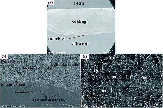 |
| | Fig. 1 Cross-section SEM micrographs of the laser clad coating: (a) overview, (b) bonding zone and heat-affected zone and (c) typical microstructure of the NiCrBSiFe composite coating at intermediate region. | |
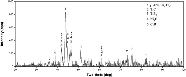 |
| | Fig. 2 X-ray diffraction results of laser clad NiCrBSiFe composite coating. | |
Table 4 EDS analysis of element composition (wt%) of laser clad composite coating
| Area |
Ni |
Cr |
B |
Si |
Fe |
C |
Ti |
Al |
V |
| A |
72.62 |
4.43 |
— |
2.17 |
3.71 |
6.86 |
9.27 |
0.94 |
— |
| B |
26.79 |
11.91 |
— |
— |
— |
12.20 |
47.05 |
2.32 |
— |
| C |
31.88 |
3.13 |
15.34 |
— |
— |
— |
48.00 |
1.65 |
— |
| D |
— |
86.32 |
6.40 |
— |
— |
2.37 |
4.90 |
— |
— |
| E |
30.94 |
2.97 |
3.99 |
0.82 |
2.33 |
7.97 |
49.11 |
2.20 |
0.37 |
3.2 Micro-hardness
The micro-hardness of laser clad NiCrBSiFe composite coatings from coating surface to substrate is plotted in Fig. 3. It includes three regions corresponding to the coating, heat-affected zone (HAZ) and substrate. It can be observed that the average micro-hardness of the composite coating is 950 HV0.5, which is almost three times that of the substrate (360 HV0.5). It is because that large amount of hard ceramic phase, such as TiC (2859–3200 HV),18 TiB2 (3400 HV)19 and CrB (21.1 GPa),20 are in situ synthesized within the γ-(Ni, Cr, Fe) matrix solid solution of the composite coating. Due to the rapid cooling of high energy laser source, the depth of heat-affected zone is about 80 μm, as shown in Fig. 3.
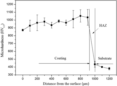 |
| | Fig. 3 Cross sectional micro-hardness profiles of laser clad NiCrBSiFe composite coatings. | |
3.3 Sliding friction and wear properties
Friction coefficients of composite coatings and Ti6Al4V alloys tested at temperatures of RT, 600 °C are shown in Fig. 4(a) and (b), respectively. All the friction coefficient of laser clad coatings and the Ti6Al4V alloys tend to be stabilized when the wear test time reach about 5 minutes. Fig. 4(c) shows the average friction coefficients of laser clad coatings and the Ti6Al4V alloys at different temperatures. It can be noticed that the NiCrBSiFe composite coatings possess the lower friction coefficients than Ti6Al4V alloys at room temperature test conditions, moreover, the friction coefficients of the Ti6Al4V alloys dramatically reduced from room-temperature (25 °C) to high-temperature (600 °C) test condition, while laser clad coatings have different tendency. The friction coefficient of the Ti6Al4V alloys and laser clad coatings are decreased from 0.52 to 0.41 and increased from 0.35 to 0.4, respectively. Lower tensile and shear strengths of Ti6Al4V alloy allow a high coefficient of friction in adhesive wear, lower hardness allow relatively easy material transfer to surface of counterpart.21 It can be observed that the friction coefficient of Ti6Al4V alloy displays fierce fluctuation. The surface of the Ti6Al4V alloy firstly adheres to the surface of the counterpart and then smeared off because of its relatively low hardness.22 Due to laser clad coating exhibits high micro-hardness, the composite coatings can decrease contact area with the counterpart that it can obviously improve the adhesive wear resistance.
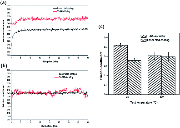 |
| | Fig. 4 Friction coefficients of the Ti6Al4V alloy and composite coatings at different temperatures. (a) 25 °C, (b) 600 °C, (c) average of 25 °C and 600 °C. | |
The wear tracks of Ti6Al4V alloy and the composite coatings at room-temperature (25 °C) and high-temperature (600 °C) test condition are shown in Fig. 5(a) and (b), respectively. It can be noticed that Ti6Al4V alloy exhibits larger width and depth of wear tracks at RT test condition, however, the composite coatings exhibit low wear volume loss. It is clear that the wear volume of Ti6Al4V alloy has reduced at high-temperature (600 °C) test condition, on the contrary, the wear volume of the composite coatings has increased. The experiment results of Mao et al.23 indicated that the surface of Ti6Al4V alloy had been protected by the tribo-layers at high-temperature wear test condition, which is in agreement with our results.
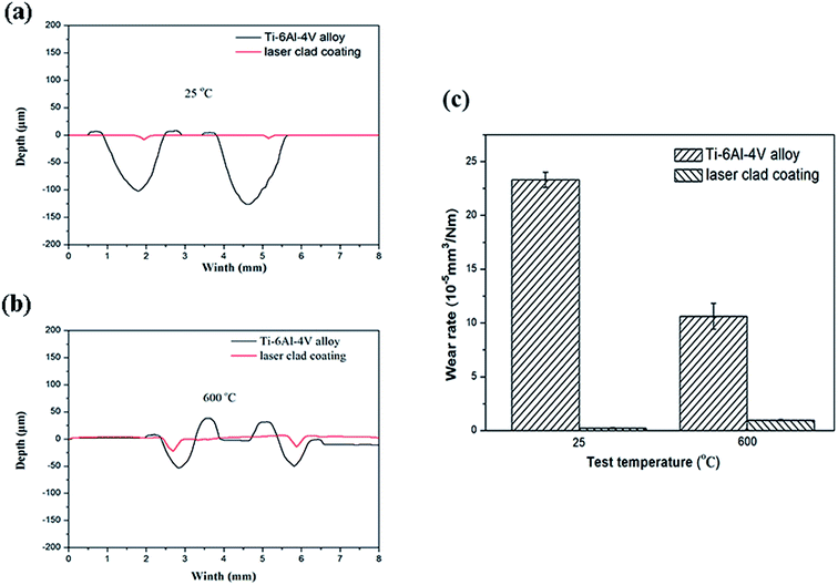 |
| | Fig. 5 Cross-sectional wear tracks at (a) room-temperature (25 °C) and (b) high-temperature (600 °C) test conditions and (c) wear rates of Ti6Al4V alloys and the composite coatings at different temperatures. | |
Fig. 6 is SEM micrographs of worn surfaces of Ti6Al4V alloy and the composite coating at room-temperature. It can be observed that the wear track width of Ti6Al4V alloy (1.7 mm) is 4 factors that of the laser clad coating (0.38 mm), the worn surface of Ti6Al4V alloy is very rough. The characterization of some wear debris, deep plowing grooves and serious plastic deformation could be obviously noticed in Fig. 6(c). The wear mechanism of the Ti6Al4V alloy specimen is severe abrasive and adhesive wear. On the contrary, the worn surface of laser clad coating is relatively smooth. It is obviously noticed that slight adhesive transferred layer peeled off from the laser clad coating, and it can be inferred that the wear mechanism of the composite coating is slight adhesive wear. Wear debris at room-temperature is shown in Fig. 7, it can be seen that the wear debris of Ti6Al4V alloy are lager plate-like and irregularly shaped particles. EDS analysis indicated that these wear debris are rich in Ti element, as shown in Fig. 7(c). It can be inferred that the wear debris are manly detached from Ti6Al4V alloy. However, the wear debris of laser clad coating is small irregular and blocky shape of transferred fragments, EDS analytic results show that wear debris has high mass percent of oxygen element, which is shown in Fig. 7(d). It can be inferred that the wear debris of laser clad coating is metal oxides, which can play solid lubrication role in the wear tests. The oxidation of the debris and the accumulation of the reaction products in the spalling pits lead to the formation of surface film, which can reduce the friction coefficient of the composite coating.24 It can corroborate the conclusion of the wear mechanism analyses of Ti6Al4V alloy and the composite coating at room-temperature.
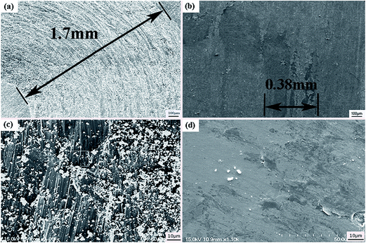 |
| | Fig. 6 SEM micrographs of worn surfaces at room-temperature (a) Ti6Al4V alloy; (b) the composite coating; (c) magnification of (a); (d) magnification of (b). | |
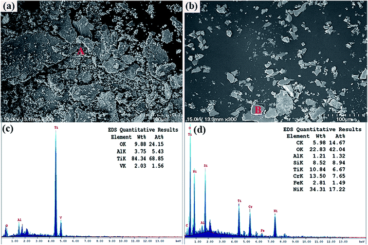 |
| | Fig. 7 SEM micrographs of wear debris at room-temperature (a) Ti6Al4V alloy and (b) the composite coating; (c) and (d) EDS pattern and quantitative results of area A in (a) and area B in (b), respectively. | |
Fig. 8 is SEM micrographs of worn surfaces of Ti6Al4V alloy and the composite coating at high temperature (600 °C). It can be noticed that the wear track width of laser clad coating (0.52 mm) is lower than Ti6Al4V alloy (1.1 mm). The covered or smeared layers occurred on the worn surfaces of Ti6Al4V alloy are shown in Fig. 8(c). SEM micrographs and EDS analysis results of element of wear debris are shown in Fig. 9. The formation of loose particles is occurred both on worn surfaces of Ti6Al4V alloy and laser clad coating. The results of Dutta Majumdar et al.25 indicated that the low friction event may have arisen due to partial lubrication offered by the three-body wear condition involving the worn-out debris. The EDS analysis results indicated that the oxygen contents of wear debris of Ti6Al4V alloy and laser clad coating are very enriched. Wear debris have been oxidized at high temperature test condition. The friction coefficients and wear rate of Ti6Al4V alloy have reduced from room-temperature (25 °C) to high-temperature (600 °C) test condition because smeared oxides surface layers present on the contact surface, preventing the contacting surface from direct metallic contact and reduce the adhesive wear. The wear mechanism of Ti6Al4V alloy is oxidative wear at high temperature text condition.26 Due to the decreasing hardness of the γ-(Ni, Cr, Fe) matrix solid solution with increasing test temperature, it can be observed that some wear debris, plowing grooves occurred on the worn surfaces of laser clad coating, the wear mechanism of laser clad coating is slight plastic deformation, abrasive wear and oxidative wear.
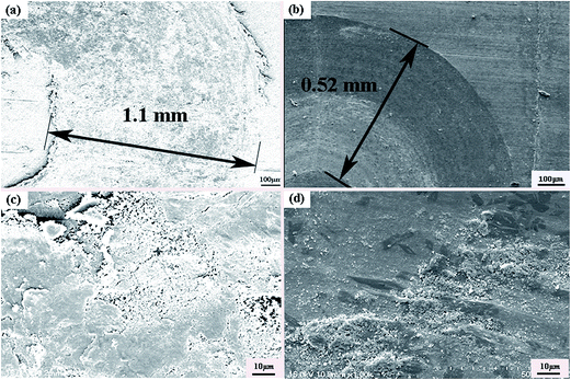 |
| | Fig. 8 SEM micrographs of worn surfaces at 600 °C (a) Ti6Al4V alloy; (b) composite coating; (c) magnification of (a); (d) magnification of (b). | |
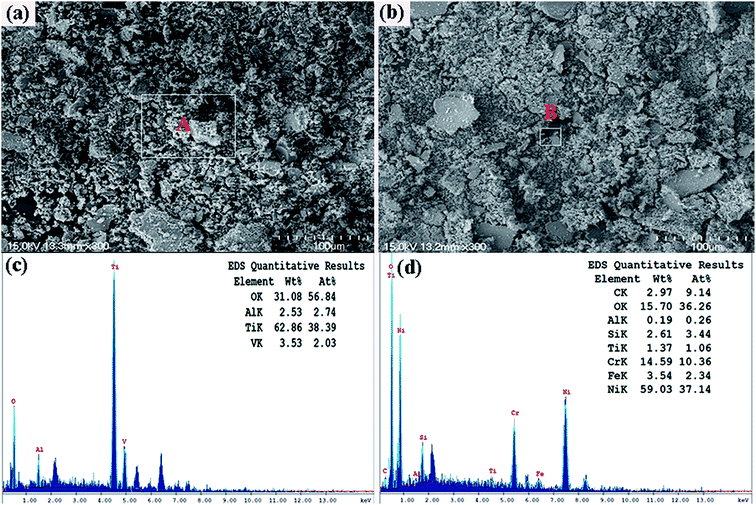 |
| | Fig. 9 SEM micrographs of wear debris at 600 °C (a) Ti6Al4V alloy and (b) the composite coating; (c) and (d) EDS pattern and quantitative results of area A in (a) and area B in (b), respectively. | |
3.4 High-temperature oxidation resistance
As for the high-temperature structural materials, the laser clad coating also needs excellent high temperature oxidation resistance. Fig. 10 is the results of the high-temperature (800 °C) oxidation tests, the results showed that the high temperature oxidation resistance of Ti6Al4V alloy has been improved by laser cladding. The X-ray diffraction results of the oxidation surface of Ti6Al4V alloy and the laser clad coating after isothermal oxidation at 800 °C for 32 h are shown in Fig. 11. It can be noticed that the diffraction peaks of TiO2 is stronger than Al2O3 in the oxidation surface of Ti6Al4V alloy. Diffraction peaks of NiO, Cr2O3, TiO2 and FeO have been found in the oxidation surface of laser clad coating. Cross-sectional SEM micrographs after oxidation at 800 °C for 32 h are shown in Fig. 12. Because TiO2 is brittle and porous materials at high temperature, it is easy to peel off and oxidized. It can be observed that the oxidation layer is very thick and cracks occurred between oxidation layer and the Ti6Al4V alloy substrate. However, the oxidation layer of the coating is very thin that can only clearly be seen by high magnification of SEM micrograph. The composite coating has excellent high temperature (800 °C) oxidation resistance due to the dense oxide scales, which can prevent the diffusion of oxygen.
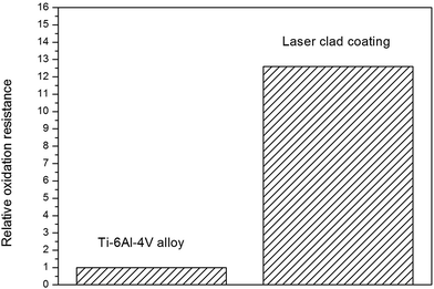 |
| | Fig. 10 Relative oxidation resistance of the laser clad coating with reference to Ti6Al4V alloy at 800 °C for 32 h. | |
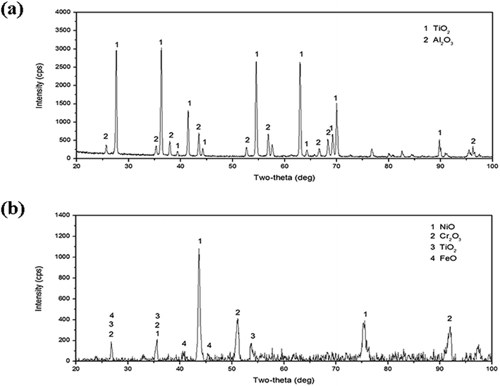 |
| | Fig. 11 X-ray diffraction results of the oxidized surface of (a) Ti6Al4V alloy and (b) the composite coating. | |
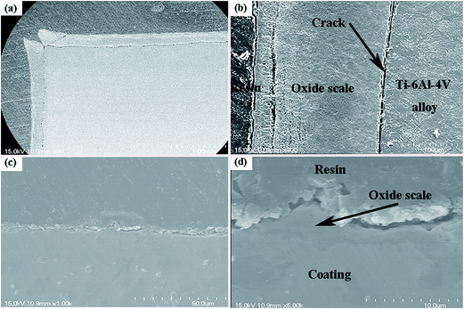 |
| | Fig. 12 Cross-sectional SEM micrographs after oxidation at 800 °C for 32 h (a) Ti6Al4V alloy; (b) composite coating; (c) magnification of (a); (d) magnification of (b). | |
4. Conclusions
In this paper, NiCrBSiFe composite coatings were successfully fabricated on Ti6Al4V alloy by laser cladding. The coatings have the γ-(Ni, Cr, Fe) as a relatively tough matrix and the in situ synthetic TiC, TiB2 CrB hard phases as reinforcements. The results are summarized as following:
(1) the composite coating has good metallurgical bonding to Ti6Al4V alloy substrate, the average micro-hardness of the composite coating is 950 HV0.5, which is almost three times that of the substrate (360 HV0.5).
(2) At room-temperature, the wear mechanism of the Ti6Al4V alloy specimen is severe abrasive wear, adhesive wear and fatigue wear, while the composite coating is slight adhesive wear. At 600 °C, the delamination and oxidation phenomena occurred on the worn surfaces of Ti6Al4V alloy, the wear mechanism of Ti6Al4V alloy is oxidative wear, while the loose wear debris occurred on the worn surfaces of laser clad coating and the wear mechanism of laser clad coating is slight plastic deformation, abrasive wear and oxidative wear.
(3) The composite coating has excellent high temperature (800 °C) oxidation resistance due to the formation of dense oxide scales, which can prevent the diffusion of oxygen.
Acknowledgements
The authors acknowledge the financial support from the Natural Science Foundation of Jiangsu Province (Grant Nos BK20141194 and BK20131155), the Opening Foundation of Jiangsu Province Key Laboratory of High-end Structural Materials (Grant No. hsm1401). One of the authors (G. X. Zhu) is also grateful for the financial support from the National Natural Science Foundation of China (Grant No. 51405319).
References
- Md. Ohidul Alam and A. S. M. A. Haseeb, Tribol. Int., 2002, 35, 357 CrossRef.
- Y. S. Tian, Q. Y. Zhang and D. Y. Wang, J. Mater. Process. Technol., 2009, 209, 2887 CrossRef CAS PubMed.
- C. Huang, Y. Z. Zhang, R. Vilar and J. Y. Shen, Mater. Des., 2012, 41, 338 CrossRef CAS PubMed.
- H. Guleryuz and H. Cimenoglu, J. Alloys Compd., 2009, 472, 241 CrossRef CAS PubMed.
- R. Cottam, V. Luzin, Q. Liu, E. Mayes, Y. C. Wong, J. Wang and M. Brandt, et al., Mater. Sci. Eng., A, 2014, 601, 65 CrossRef CAS PubMed.
- M. Zarezadeh Mehrizi, M. Shamanian, A. Saidi and R. ShojaRazavi, Ceram. Int., 2014, 40, 13447 CrossRef CAS PubMed.
- S. D. Sun, Q. C. Liu, M. Brandt, V. Luzin, R. Cottam, M. Janardhana and G. Clark, Mater. Sci. Eng., A, 2014, 606, 46 CrossRef CAS PubMed.
- J. M. Chen, C. Guo and J. S. Zhou, Trans. Nonferrous Met. Soc. China, 2012, 22, 2171 CrossRef CAS.
- X. M. He, X. B. Liu, M. D. Wang, M. S. Yang, S. H. Shi, G. Y. Fu and S. F. Chen, Appl. Surf. Sci., 2011, 258, 535 CrossRef CAS PubMed.
- Q. Li, G. M. Song, Y. Z. Zhang, T. C. Lei and W. Z. Chen, Wear, 2003, 254, 222 CrossRef CAS.
- A. Zikin, M. Antonov, I. Hussainova, L. Katona and A. Gavrilović, Tribol. Int., 2013, 68, 45 CrossRef CAS PubMed.
- R. Fernández, A. García, J. M. Cuetos, R. González, A. Noriega and M. Cadenas, Wear, 2015, 324–325, 80 CrossRef PubMed.
- X. Luo, J. Li and G. J. Li, J. Alloys Compd., 2015, 626, 102 CrossRef CAS PubMed.
- M. Aristizabal, L. C. Ardila and F. Veiga, Wear, 2012, 280–281, 15 CrossRef CAS PubMed.
- X. Q. Li, M. N. Zhang, D. H. Zheng, T. Cao, J. Chen and S. G. Qu, J. Alloys Compd., 2015, 629, 148 CrossRef CAS PubMed.
- O. Belahssen, A. Chala, H. B. Temam and S. Benramache, RSC Adv., 2014, 4, 52951 RSC.
- X. B. Liu and H. M. Wang, Chin. J. Lasers, 2005, 32, 1143 CAS . (In Chinese).
- Y. Cui, Z. X. Guo, H. Y. Wang and J. D. Hu, J. Mater. Process. Technol., 2007, 183, 380 CrossRef PubMed.
- B. S. Du, Z. D. Zou, X. H. Wang and S. Y. Qu, Mater. Lett., 2008, 62, 689 CrossRef CAS PubMed.
- S. Okada, K. Kudou, K. Iizumi, K. Kudaka, I. Higashi and T. Lundström, J. Cryst. Growth, 1996, 166, 429 CrossRef CAS.
- S. Taktaka and H. Akbulut, Tribol. Int., 2007, 40, 423 CrossRef PubMed.
- Y. Wu, A. H. Wang, Z. Zhang, H. B. Xia and Y. N. Wang, Surf. Coat. Technol., 2014, 258, 711 CrossRef CAS PubMed.
- S. Mao, L. Wang, K. M. Chen, S. Q. Wang and X. H. Cui, Wear, 2013, 297, 1032 CrossRef PubMed.
- W. Chen, Y. M. Gao, C. Chen and J. D. Xing, Wear, 2010, 269, 241 CrossRef CAS PubMed.
- J. Dutta Majumdar, B. L. Mordike and I. Manna, Wear, 2000, 242, 18 CrossRef.
- Y. Xue and H. M. Wang, Appl. Surf. Sci., 2005, 243, 278 CrossRef CAS PubMed.
|
| This journal is © The Royal Society of Chemistry 2015 |
Click here to see how this site uses Cookies. View our privacy policy here. 


