DOI:
10.1039/C5RA14590B
(Paper)
RSC Adv., 2015,
5, 94933-94948
Conducting poly(o-anisidine-co-o-phenyldiammine) nanorod dispersed epoxy composite coatings: synthesis, characterization and corrosion protective performance†
Received
23rd July 2015
, Accepted 2nd October 2015
First published on 7th October 2015
Abstract
Conducting polymers (CPs) have been significantly contributing to the development of high performance new-generation anti-corrosive coatings. CP nanofiller dispersed insulating polymer coatings effectively prevent the transport of corrosive ions (H+, O2−, Cl−, OH− etc.) at the coating–metal interface, via a barrier or redox mechanism. In view of this, for the first time, we report the synthesis of poly(o-anisidine-co-o-phenyldiammine) P(oA-co-oPDA) copolymer conducting nanorods. Poly(o-anisidine) (PoA) conducting nanoparticles were also synthesized laterally. The formulations of these nanofiller dispersed epoxy-polyamide (PA) nanocomposite coating systems have also been reported. The structural elucidation was performed by FT-IR, UV-Vis, and 1H NMR spectroscopy. The crystallinity, surface area and morphology of the fillers were analysed by XRD, BET, SEM and TEM techniques. The thermal stability and hydrophobic behaviour were investigated using TGA, DSC and contact angle measurements. The physico-mechanical properties and corrosion protective performance of these coatings were evaluated using standard methods. The salt spray test, potentiodynamic polarization (PDP) and electron impedance spectroscopy studies (EIS) were conducted in 5 wt% NaCl and 5 wt% HCl media. The physico-mechanical properties, corrosion protection performance and Raman studies revealed that the P(oA-co-oPDA)-epoxy-PA nanocomposite coating exhibited superior performance when compared to PoA-epoxy-PA, epoxy-PA and other such nanocomposite coatings.
1. Introduction
Corrosion of structural materials is considered to be a serious problem for industries and it impacts the economy of the country. Generally, three approaches are being used to reduce such an undesirable natural process, causing huge losses to metallic materials, and they are: (i) cathodic protection1 (ii) anodic protection (passivation)2 and (iii) application of barrier coatings.3 Further significant progress has been made in the designing of nano CP coatings. Thus, the focus of scientific research has shifted towards the development of a new generation of smart CP based protective coating materials, possessing high wear and corrosion resistance ability.3
Conducting polymers such as PANI, PPy and PTh seem to be interesting materials that find applications in fundamental engineering and technology research fields.4 Among them PANI and its derivatives are considered to be the most promising materials because of their ease of synthesis, non-toxicity, high electrical conductivity, chemical stability, redox reversibility and low cost. These polymers, due to their excellent anti-corrosive ability and environmental stability, have attracted considerable attention in the corrosion inhibition and protective coating field. However, their poor solubility and certain difficulties in their processing,5 limits their application in the paints and coatings field. To overcome all such issues, several steps have been taken such as formulation of their composite materials through the addition of CP fillers, dispersion and their copolymerization using chemical and electrochemical techniques, which synergistically enhances their performance. Among the PANI derivatives, poly(o-anisidine) is one of the most significant members owing to its ease of synthesis, availability and low cost.5 o-Phenyldiammine is considered as one of the prominent derivatives of PANI.6 The aromatic diammine based polymers are found to be more significant since they possess novel functionality of conjugation and terminal free amino groups in the repeating unit of their polymer chains. Furthermore, the copolymerization of o-phenyldiammine has remarkably improved some properties like stability, conductivity and solubility.7 In the literature there are many reports3,8,9 available, on PANI, PPY, PTh, and their derivatives and copolymers, which have been shown to be promising anti-corrosive coating materials, e.g., Jadhav et al. synthesized PoA via emulsion polymerization and reported its dispersion in alkyd to develop a coating on mild steel, which exhibited corrosion protection ability (Icorr for PoA/alkyd: 0.48 μA cm−2 and PANI/alkyd: 0.4 μA cm−2 in 5% HCl).10 Chaudhari et al. have electrochemically synthesized polyethoxyaniline and studied its protective behaviour on carbon steel in 3% NaCl solution using EIS and potentiodynamic studies.11 Yao et al. have synthesized aniline-p-phenyldiammine copolymers and reported their corrosion protection performance using electrochemical measurements,12 their Icorr value in 5% NaCl medium was found to be 0.06 μA cm−2. Similarly, Ping et al. have demonstrated the synthesis and the formulation of aniline-p-phenyldiammine copolymers using TX-8 emulsifier as the surfactant. They found that the composite coatings based on an epoxy matrix possessed good corrosion resistance properties.13 Liu et al. prepared PANI by conventional oxidative polymerization with a leaf like morphology and when it was used as a coating material it was found that the coating exhibited high Ecorr and low Icorr values.14 All of these works have encouraged us to develop a copolymer of o-anisidine and oPDA which possesses excellent anti-corrosive properties analogous to those of the homopolymers, which has not been reported in the literature till now. Thus, the aim of the present work is to investigate the synthesis and characterize the physico-mechanical and anti-corrosive properties of PoA and P(oA-co-o-PDA) copolymer nanocomposite coatings using epoxy-PA as a matrix. These studies revealed that the P(oA-co-oPDA)-epoxy-PA nanocomposite coatings exhibited excellent anti-corrosion performance when compared to those of epoxy-PA, PoA-epoxy-PA and other such reported coating systems.10,12,15–17
2. Experimental
2.1 Materials
ortho-Anisidine monomer (C6H9NO, MW 123.16 g mol−1 and density 1.0923 g cm−3), Merck, Germany, o-phenyldiammine (1,2 benzenediammine, C6H8N2, MW-108.14, mp 101–103 °C) ethyl methyl ketone, hydrochloric acid (HCl), S.D fine chem., Mumbai, epoxy (DGEBA, D.E.R 332, epoxy equivalent 180–185, sp.gr. 1.2306, refractive index 1.5685, viscosity about 10
000 CP), DOW Chemicals, ammonium peroxydisulphate (APS), Tergitol (NP-9), Sigma-Aldrich, USA, polyamide (PA) as a curing agent (Aradur HY 840-1 EN, CAS no. 112-24-3, amine number 500-580), Shankar dyes, New Delhi, India were used as received. All chemicals were of analytical grade and used as received.
2.2 Synthesis of PoA nanoparticles and P(oA-co-oPDA) copolymer nanorods
2.0 g of o-anisidine was taken in a three necked flat bottom flask containing 100 ml of 0.1 M HCl along with a magnetic bar and kept on a magnetic stirrer. A 30 ml solution of APS in 1 M HCl was added dropwise to the above reaction mixture, simultaneously, a 30 ml solution of 0.5 g Tergitol-X (NP-9) in 1 M HCl was added to the reaction mixture, and this was followed by the reaction proceeding under continuous stirring at ambient temperature (30 °C) for 6 h and allowed to further proceed for 24 h at a temperature range of 0–5 °C in an ice bath. The progress of the reaction was monitored by the change in colour of the solution of the reaction mixture i.e. from dark green to black and FT-IR spectra, which were taken at regular intervals of time. At the end of the reaction black coloured PoA nanoparticles were formed, which were filtered and washed several times with methanol to remove the unreacted moieties, and dried in a vacuum oven at 70 °C for 2 days at 10 mmHg pressure.
The synthesis of the black coloured P(oA-co-oPDA) copolymer nanoparticles was performed using the same reaction set-up and procedure used for PoA. 1.10 g of o-phenyldiammine monomer was added in the reaction mixture used for PoA, and the reaction was carried out accordingly. On completion of the reaction, black coloured nanorods (100–120 nm) were formed, as seen in Fig. 1a. The formation of the PoA nanoparticles and P(oA-co-oPDA) nanorods was confirmed by TEM studies. The yield% of the vacuum dried PoA and P(oA-co-oPDA) were found to be 68% and 71% respectively.
 |
| Fig. 1 (a) Scheme for the formulation of P(oA-co-o-PDA) copolymer nanorods and nanocomposites. (b) Scheme for the formulation of DGEBA epoxy-polyamide (PA). | |
2.3 Preparation of PoA-epoxy-PA and P(oA-co-o-PDA)-epoxy-PA nanocomposites
The PoA-epoxy and P(oA-co-o-PDA)-epoxy nanocomposites were prepared using different loadings of PoA (1.0, 1.5 and 2 wt%) and P(oA-co-o-PDA) (1.0, 2.0 and 3.0 wt%) by a solution blending technique in a solution of 80 wt% of epoxy in ethyl methyl ketone. The dispersion of these nanofillers in the epoxy matrix was performed by ultrasonication for 30 min and 20 min followed by mechanical stirring for 8 h and 5 h respectively at room temperature, and this resulted in the formation of a homogeneous composite solution. The nanocomposite solutions were kept under observation for a fortnight to see if there was any phase separation or not. However, no such separation was observed. The loading of P(oA-co-oPDA) in the epoxy showed uniform dispersion only up to 3.0 wt% while that of PoA is up to 1.5 wt%. Beyond these loadings, agglomeration and phase separation was observed in both cases.
2.4 Formulation of nanocomposite coatings
The 30 phr PA was homogeneously mixed in the 80 wt% solutions of epoxy, PoA-EMK and P(oA-co-o-PDA)-epoxy in EMK (Fig. 1b). Their coatings were prepared by a brush technique on finely polished, washed and rinsed CS strips of standard sizes. These coatings were cured at room temperature within 12 h, 5 h and 45 min respectively. The average thickness of the coatings was found to be around 130 μm. The minimum curing time in the case of the P(oA-co-o-PDA)-epoxy-PA nanocomposite coatings can be attributed to the presence of –NH groups that enhance the condensation curing reaction.
2.5 Characterization
The structural elucidation of the PoA nanoparticles, P(oA-co-o-PDA) copolymer nanorods, epoxy-PA and their nanocomposites was carried out using Fourier transform infrared (FT-IR) spectroscopy performed on a PerkinElmer 1750 FT-IR spectrophotometer (PerkinElmer Instruments, Norwalk, CT) with KBr pellets, and 1H-NMR on a JEOL GSX 300 MHz FX-100 in DMSO using TMS as the internal standard. UV-visible spectra were taken on a Perkin-Elmer-Lamda-Ez-221. The particle size and surface morphology analyses were carried out by transmission electron microscopy (TEM) with a Morgagni 268-D TEM, FEI, USA operated at an accelerating voltage of 120 kV. Scanning Electron Microscopy (SEM) was carried out on a FEI Quanta 200F with Oxford-EDS system IE 250 X Max 80. BET analysis was conducted with the help of a Quanta Chrome instrument (model NOVA 2000e USA) using a nitrogen gas environment to determine the surface area of P(oA-co-oPDA). The crystalline nature and phase purity were investigated using an X-ray diffractometer (Philips W3710) and Cu Kα radiation. Thermogravimetric analysis (TGA) was performed on a SII EXSTAR 6000 thermal analyzer (Japan) from 40 °C to 800 °C under nitrogen environment at a flow rate of 10 °C min−1. The hydrophobic behaviour of the coatings was evaluated by contact angle measurements using a drop Shape Analysis System (model DSA10MK2Kruss GmbH, Germany) with a high speed CCD camera for image capture.18 The carbon steel specimens were polished successively with different grades of emery papers (600–800–1000) and were washed thoroughly with double distilled water, degreased with methanol and acetone and dried at room temperature. These coating materials were applied by a brush on the finely polished CS strips (2.87% C and 97.13% Fe) of standard size (70 × 30 × 1 mm3) and used for the determination of the physico-mechanical properties of specular gloss at 45° by a gloss meter (model RSPT-20, digital instrument Santa Barbara, CA) and in the scratch hardness test (BS 3900), bend test on a 1/8 inch conical mandrel (ASTM D 3281-04), cross-hatch test (ASTM D3359), methyl ethyl ketone (MEK) solvent rub resistance test (ASTM D5402) and impact resistance test (IS: 101 par 5/sec-31988). The conductivity was measured by the standard four probe method using a Keithley DMM 2001 and EG and G Princeton Applied Research potentiostat model 362 as a current source. For each value, three specimens were used for the measurement of conductivity. The mean averages of five values of the conductivity were taken. The corrosion resistance performance of the P(oA-co-o-PDA)-epoxy-PA, PoA-epoxy-PA and epoxy-PA coated CS strips was evaluated by potentiodynamic polarization measurements and electrochemical impedance spectroscopy in NaCl (5 wt%) and HCl (5 wt%) at room temperature (30 °C) using a micro Autolab type III with a FRA unit (μ3AVT 70762, Netherlands) potentiostat. The Tafel plots in the presence of the aforementioned corrosive media were obtained using a three-electrode electrochemical cell (EG&G 362) containing a platinum gauze as the counter electrode, Ag/AgCl as the reference electrode and the test specimen (coated and uncoated carbon steel specimens) as the working electrode. The test specimens were fitted in an electrochemical cell with a 1 cm2 area of the sample exposed to the corrosive media.19 The potentiodynamic polarization tests were carried out in the potential range ±100 mV (with respect to OCP) at a 0.001 mV s−1 scan rate. The Nova 1.8 software was used for data fitting and calculation of results. The impedance and Tafel parameters were determined by the curve fitting programme available in the aforementioned software. Each test was run in triplicate to verify the reproducibility of the data.
3. Results and discussion
3.1 Structural elucidation
3.1.1 FT-IR analysis. The FT-IR spectrum (Fig. 2a and b) of P(oA-co-oPDA) showed the presence of an intense NH stretching vibration (νstr) band at 3350 cm−1. The C
N (νstr) and C
C (νstr) stretching bands for the quinonoid (Q) and benzenoid (B) rings appeared at 1595 cm−1 and 1505 cm−1 respectively. The peak at 1244 cm−1 was assigned to the C–N stretching peak for the benzenoid rings, and the peak at 1256 cm−1 showed the C–O aromatic peak of the benzene ring. The C–H bending vibration formed during protonation was confirmed by the presence of the peak at 1112 cm−1. The C–O–C peak at 1147 cm−1 for the ether group was observed. The other band at 848 cm−1 revealed the presence of phenazine units.20 The band at 754 cm−1 revealed the presence of 1,2 substitutions of the NH2 group at the 1st position and the OCH3 group at the 2nd position respectively. The absorption bands of PoA had all of the peaks except the phenazine unit band shown in an earlier study.10 The band at 820 cm−1 was used so as to find out the difference in the N–H stretching mode (3350 cm−1) in the P(oA-co-oPDA) copolymer and PoA, and it was found to be stronger for the copolymer nanorods. This implies that P(oA-co-oPDA) contains more end capped amino groups. In addition, the bands at about 742 cm−1 and 692 cm−1 were observed in P(oA-co-oPDA) which confirmed the presence of P(oA-co-oPDA) oligomers. The absorption bands of PoA had all of the characteristic peaks except the phenazine unit, which suggests the formation and confirmation of the copolymer.
 |
| Fig. 2 (a and b) FT-IR spectra of epoxy matrix, P(oA-co-o-PDA) copolymer nanorods and P(oA-co-o-PDA)-epoxy nanocomposite. | |
The FT-IR spectrum (Fig. 2), of the epoxy showed a characteristic band at 3449 cm−1 associated with the broad OH stretching of the hydroxyl groups. The peaks appearing in the range of 1296–1184 cm−1 were correlated to the C–O–C of aryl alkyl ether, while the peak at 1095 cm−1 was attributed to the aryl alkyl ether symmetric stretching (sym). The oxirane ring peaks appeared at 910–830 cm−1.
The FT-IR spectrum (Fig. 2) of 2.0% P(oA-co-oPDA)-epoxy showed that the OH stretching vibration peak at 3460 cm−1 was broader in wavelength, which shifted by 14 cm−1, when compared to the epoxy matrix. The presence of the peaks at 1390, 1438 and 1508 cm−1 corresponded to the benzenoid and quinonoid stretching modes of P(oA-co-oPDA). The benzenoid and quinonoid vibration peaks were very intense and pronounced indicating the strong interaction between P(oA-co-oPDA) and epoxy. These bands suggested a conjugated pi-bond system, which may be attributed to the doped state of P(oA-co-o-PDA).8 As the doping improves the conductivity levels, polaron/bipolaron structures form, resulting in the increase of charge transfer in P(oA-co-oPDA) and also higher electronic delocalization. The presence of conjugated double bonds in the benzenoid and quinonoid rings permits electron mobility throughout the P(oA-co-oPDA) chains, which is responsible for more electron delocalization and results in the conducting nature of nanocomposite. The NH stretching vibration band of P(oA-co-oPDA) overlaps the OH stretching vibration which revealed the electrostatic interaction of the NH group of P(oA-co-oPDA) and OH group of epoxy via strong hydrogen bonding.21,22 All other peaks, which corresponded to epoxy, did not exhibit any major shift. Hence, the formation of the P(oA-co-o-PDA)-epoxy as nanocomposite was confirmed.
3.1.2 NMR analysis. The 1H NMR (Fig. 3, ESI: Fig. S1a and b†) of P(oA-co-oPDA) revealed the presence of peaks between δ = 6.6 and 7.4 ppm, which corresponded to the aromatic protons. Similarly, the 1H NMR spectra of PoA reported in an earlier study23 have characteristic peaks in this region but of slightly less intensity. The peak at δ = 3.4 ppm corresponds to the OCH3 group and the two peaks at δ = 3.7 ppm are for –NH and –NH2.12 The singlet signal at δ = 2.5 ppm was correlated to the solvent protons.
 |
| Fig. 3 1H NMR of P(oA-co-o-PDA) nanorods. | |
3.1.3 UV-visible analysis. The UV-visible spectrum (Fig. 4) of P(oA-co-oPDA) revealed the presence of characteristic peaks at 260 nm and 285 nm, which were assigned to the π–π* transition in the benzenoid ring. The peak at 430 nm was assigned to the donor acceptor interaction of the quinoid amine units (–C
N–).24
 |
| Fig. 4 UV-Vis absorption spectrum for P(oA-co-o-PDA) nanorods. | |
3.2 Particle size, morphology and surface area
3.2.1 TEM and SEM/EDAX analysis. The formation of tubular shaped P(oA-co-oPDA) nanorods of dia. ca. 100–120 nm (approaching the nanoscale) was confirmed by TEM analysis (Fig. 5a).24 The SEM studies (Fig. 5b–d) ESI: Fig. S2† were in concordance with the TEM results showing the presence of nanorods with a specific morphology, the EDAX (Fig. 5d) analysis clearly confirmed the presence of N, C, H elements etc. in the nanorods. The TEM micrograph (Fig. 5e) of PoA (a homopolymer) showed well dispersed rice shaped nanoparticles of dia. 25–30 nm. The TEM micrograph of the P(oA-co-o-PDA)-epoxy-PA nanocomposite (Fig. 5f) showed well dispersed P(oA-co-oPDA) nanorods of 90–95 nm size within the epoxy-PA matrix. The electrostatic interactions of the NH groups of the nanofiller and that of PA with the oxirane groups of epoxy lead to the formation of physical bonds between the filler and the matrix, which confirmed the formation of the nanocomposites. The improved properties of the P(oA-co-o-PDA)-epoxy-PA nanocomposite can be attributed to the presence of doped nanorods, which were homogeneously dispersed within the polymer matrix and effectively induced adhesion between the nanocomposite coating and metal surface through the electrostatic interactions between the positively charged metal surface and the negatively charged pendent groups of the matrix which resulted in the formation of a well-adhered homogeneous and compact coating on the CS surface.
 |
| Fig. 5 (a) TEM micrograph of P(oA-co-o-PDA) nanorods, (b) SEM micrograph of P(oA-co-o-PDA) nanorods, (c) enlarged view of SEM of single P(oA-co-o-PDA) nanorod, (d) SEM/EDAX of P(oA-co-o-PDA) nanorods, (e) TEM micrograph of PoA nanoparticles, (f) TEM micrographs of 3.0% P(oA-co-o-PDA)-epoxy nanocomposite. | |
3.2.2 BET analysis. BET analysis of the P(oA-co-oPDA) nanorods confirmed the porous nature and higher surface area of the nanorods. The average surface area was found to be 281.30 m2 g−1 with a pore size of 1.51 Å. The porous nature of the nanorods has suggested that these particles may also have potential for application in the field of adsorption and catalysis reactions. The nanoscale porosity introduced nanoscale roughness in the coating materials, which resulted in the enhanced hydrophobicity and reduced wettability of the coating surface which improved the corrosion protective efficiency of the coatings.25
3.3 Crystalline nature
3.3.1 X-ray diffraction. X-ray diffraction studies were performed to analyse the crystalline structure and identify the phase of P(oA-co-oPDA). The XRD diffractogram (Fig. 6) showed pronounced peaks at θ = 22° and 25°, which can be correlated to the (0 2 0) reflection26 and local crystallinity. A broad band centred at 2θ = 11° and 15°, revealed the partial crystalline nature of the nanorods and this might have been caused by the NH2 (ammine) groups present perpendicular to the polymer chain resulting in the formation of semi-crystalline, short range nanorods, particularly in the case of HCl doped CPs. Thus the confirmation of the semi-crystalline nature of the copolymer from the X-ray results was in agreement with the XRD diffractogram of PoA given in an earlier study27 which showed that a broad hump, spanning between θ = 20° and 30°, was responsible for its amorphous nature.
 |
| Fig. 6 XRD analysis of P(oA-co-o-PDA) nanorods. | |
3.3.2 Solubility test. The solubility of the epoxy (matrix), PoA nanoparticles, P(oA-co-oPDA) copolymer and their nanocomposites were investigated in various polar and non-polar solvents at room temperature. The P(oA-co-oPDA) copolymer was dispersed better in polar solvents such as methyl alcohol, ethyl alcohol, DMSO, DMF and NMP when compared to non-polar solvents. This can be attributed to the presence of –NH groups and oxygen atoms in P(oA-co-oPDA), which are more electronegative and have a lone pair of electrons that induces electrostatic interactions between the oxygen and hydrogen atoms of the constituent moieties.28 Thus, the hydrogen atoms of the organic solvents were attracted to the lone pair of electrons of the negatively charged oxygen atom present in P(oA-co-oPDA) to form hydrogen bonds. This can be attributed to the lone pair orbital of the oxygen atom projected within the space away from the positively charged nuclei, promoting considerable charge separation. Hence, higher dispersion was observed in the polar solvents when compared to non-polar solvents. The solubility of the PoA nanoparticles in the polar solvents was found to be lower than that of the P(oA-co-oPDA) copolymer. Similarly, the epoxy matrix and P(oA-co-o-PDA)-epoxy-PA nanocomposites, which have polar hydroxyl, oxirane, and amino moieties, exhibit enhanced solubility in polar solvents like methanol, ethyl methyl ketone, DMSO, and NMP but they are only partially soluble in acetone (Table 1).
Table 1 Solubility test
Solvents |
Solubility |
Epoxy |
PoA |
P(oA-co-oPDA) copolymer |
Xylene |
Insoluble |
Insoluble |
Insoluble |
DMF |
Soluble |
Soluble |
Soluble |
DMSO |
Partly soluble |
Soluble |
Soluble |
Toluene |
Insoluble |
Partially soluble |
Insoluble |
CCl4 |
Insoluble |
Insoluble |
Insoluble |
THF |
Insoluble |
Insoluble |
Insoluble |
Acetone |
Partially soluble |
Partially soluble |
Partially soluble |
Benzene |
Insoluble |
Insoluble |
Insoluble |
Ethylmethyl ketone |
Soluble |
Soluble |
Soluble |
Ethanol |
Insoluble |
Soluble |
Partially soluble |
Methanol |
Soluble |
Soluble |
Soluble |
NMP |
Insoluble |
Soluble |
Partially soluble |
3.4 Thermal stability
3.4.1 Thermal analysis. TGA and DSC analysis were performed to examine the thermal stability of the polymer. TGA with DTG and DSC curves are shown in Fig. 7. The P(oA-co-PDA) copolymer showed a three step decomposition process.
 |
| Fig. 7 TGA of P(oA-co-o-PDA) nanorods. | |
The initial loss of (5–10%) up to 120 °C can be attributed to the evaporation of superficial moisture, other volatile compounds, intermediate oligomers, as well as unreacted monomer elimination. Then, at higher temperatures from 180 °C to 280 °C, the second weight loss (55–70%) occurred, which can be attributed to the aliphatic and protonic acid components of the polymer29 which were lost in this temperature range. This was also attributed to the removal of dopants (Cl−), low oligomers or side products as well as to the destruction of the NH+⋯Cl− interaction between the PoA chain and Cl− dopant in this temperature range.30 The third sluggish decomposition (wt loss 60%) in the region of 420–800 °C was assigned to the degradation of the backbone units of oPDA (benzenoid and quinoid units)24 along with the –NH2 moiety from the benzene ring chain and finally at more extreme temperatures the polymer chain breaks and this leads to the production of various gases such as C2H2 or NH3. All of the results were in concordance with the DSC data (Fig. 7) which possess three exotherms at these temperatures responsible for the three stage decomposition of the P(oA-oPDA) nanorods (AFM image ESI: Fig. S3†).
The DSC gives information on the energy absorbed or liberated during the thermal treatment of the polymers. This study indicated that three exothermic reactions occur between 250 °C and 400 °C. The exothermic reaction suggests that the formation of highly cross-linked P(oA-co-oPDA) copolymers. The energy released at around 280 °C in the second step can be corroborated to the breaking of the NH+⋯Cl− interaction between the PoA chain and Cl dopant. The third exotherm at around 420 °C, can be ascribed to the degradation of the backbone units of oPDA (benzenoid and quinoid units) along with the –NH2 moiety respectively.31
3.4.2 Conductivity studies. The conductivity of CPs mainly depends on the number of charge carriers and the conjugation length within the polymer backbone. The conductivity measurements were carried out under ambient conditions. The conductivity of pristine PoA was found to be 5.02 × 10⁻³ S cm−1 while that of oPDA was found to be 1.1 × 10⁻⁷ S cm−1. On the other hand, the conductivity of the P(oA-co-oPDA) copolymer was found to be 4.2 × 10⁻² S cm−1, which was more comparable with that of PANI. The conductivity of o-PDA was low due to the bulky-NH2 substituents/groups that are present in the polymer, which stops the main chain twisting. The literature shows that the conductivity of the copolymer containing PoA and oPDA decreases with the increased loading of the o-PDA polymer in the co-polymer P(oA-co-oPDA) which is present in a low amount (0–20 mol% only). This further reduces its coplanarity and results in a barrier to interchain interactions and the jumping of e−s, therefore shortening the conjugation length.
3.4.3 Surface wettability test. The hydrophobic behavior of the coatings was analysed with deionized water for the evaluation of the hydrophobic properties of the coated substrate. Angle measurements were done in triplicates. Water was taken in a syringe and its drops (15 μl) were allowed to fall on the substrate, the left and right contact angles were measured for 10 s at 1 s intervals. The average contact angle was calculated by using the three values of the left and right contact angles. The CCD camera images of the water droplets on the surface of the coatings are shown in Fig. 8. The contact angle analysis revealed that the highest value was observed in the copolymer (PoA-co-oPDA)-epoxy-PA nanocomposite coatings (92°) followed by PoA-epoxy-PA (79°) and epoxy-PA coatings (62°). The highest contact angle value for the copolymer nanocomposite coatings can be attributed to the presence of higher roughness at the nanoscale that lead to the formation of air pockets within the coating which are responsible for the decrease in wettability.32 Hence the amplified contact angle is accountable for the improved hydrophobicity of the coatings, which is considered to be an important parameter required for the effective anticorrosive behaviour of coatings.33
 |
| Fig. 8 Contact angle images of neat epoxy, P(oA-co-o-PDA)-epoxy-PA and PoA-epoxy-PA nanocomposites. | |
3.4.4 Physico-mechanical properties. The physico-mechanical properties of epoxy-PA, PoA-epoxy-PA and P(oA-co-oPDA)-epoxy-PA coated CS are given in Table 2. The average coating thickness was found to be 110–120 μm for epoxy-PA, 120–125 μm for PoA-epoxy-PA and 125–135 μm for the P(oA-co-oPDA)-epoxy-PA nanocomposite coatings respectively. The scratch hardness values were found to increase in the order of P(oA-co-oPDA)-epoxy-PA (12.9 kg) > PoA-epoxy-PA (9.7 kg) > epoxy-PA (6.5 kg) coatings, this trend can be attributed to the extent of cross-linking which restricted the indentation. The improved scratch hardness values of the coatings can be attributed to the ladder structure of the P(oPDA) polymer.34 The high scratch hardness value of the P(oA-co-oPDA)-epoxy-PA coated samples can also be attributed to the enhancement in the adhesion between the P(oA-co-oPDA)-epoxy-PA coating and metal substrate. The enhanced adhesion between the epoxy-PA, PoA-epoxy-PA and P(oA-co-oPDA)-epoxy-PA coatings with CS was further confirmed by the cross-hatch test. The optical images (Fig. 9a and b) of the coated CS before and after the cross hatch test showed no spalling of the coating was observed in the case of P(oA-co-oPDA)-epoxy-PA while spalling was observed in the case of PoA-epoxy-PA and epoxy-PA coatings. No change in the gloss of these coatings was found and this can be attributed to their opaque nature and black colour. Both the PoA-epoxy-PA and P(oA-co-oPDA)-epoxy-PA coatings passed the impact test. This revealed that the coatings absorbed the highest limit of impact energy due to the presence of the flexible long chain carbon moieties like polar hydroxyls and oxirane functionalities present in the backbones of the polymeric chains of the nanocomposites along with the presence of strong hydrogen bonding.35 The flexibility of the coatings was determined by the bending test with the help of a conical mandrel. The coatings were found to be flexible as they bend without any damage or fracture. The MEK double rub cycle test values of all of the coated CS samples are given in Table 2 and were higher than 400 cycles. The physico-mechanical performances of the 3.0 wt% of P(oA-co-o-PDA)-epoxy-PA and 1.5 wt% of PoA-epoxy-PA coatings were the best among all of the ratios of these coatings prepared and were further analysed for their corrosion protective performance using advance techniques like PDP and EIS electrochemical studies.
Table 2 Physico-mechanical properties of epoxy, PoA-epoxy-PA and PoA-co-oPDA-epoxy-PA nanocomposite coatings
Test |
Epoxy |
PoA-epoxy-PA |
P(oA-co-oPDA)-epoxy-PA |
Scratch hardness |
6.5 kg |
11.2 kg |
12.9 kg |
Impact resistance |
150 lb per inch |
150 lb per inch |
150 lb per inch |
Gloss at 45° |
38 |
35 |
33 |
Bending 1/8 inch |
Pass |
Pass |
Pass |
Cross hatch test |
Pass |
Pass |
Pass |
MEK double rub cycle test |
>400 |
>400 |
>400 |
 |
| Fig. 9 Optical images of P(oA-co-o-PDA) copolymer coated CS (a) before cross hatch test, (b) after cross hatch test and (c) after EIS studies (5% NaCl). | |
3.5 Corrosion studies
3.5.1 PDP studies. The potentiodynamic polarization experiments were conducted for the quantitative analysis of the anticorrosive performance of P(oA-co-oPDA)-epoxy-PA, PoA-epoxy-PA, and epoxy-PA coated CS and bare CS (Fig. 10a and b). Electrochemical parameters such as corrosion current density (Icorr), corrosion potential (Ecorr), and the β anodic and β cathodic values (Tafel slopes ba and bc) of coated and uncoated CS were investigated with the help of the potentiodynamic polarization curves given in Fig. 10 and Table 3. The Stern–Geary equation36 given below was further used to calculate the polarization resistance Rp and the ba and bc values (dE/d
log
I)37
 |
| Fig. 10 (a) Potentiodynamic polarization studies of uncoated and coated CS in 5.0 wt% HCl. (b) Potentiodynamic polarization studies of uncoated and coated CS in 5.0 wt% NaCl where (A) CS (B) epoxy (C) PoA-epoxy-PA and (D) P(oA-co-oPDA)-epoxy-PA nanocomposite coatings. | |
Table 3 Electrochemical parameters obtained from PDP and EIS studies for uncoated and coated CS in 5% HCl at room temperature
Sample code |
Ecorr (V) |
Icorr (A cm−2) |
Rp (Ω) |
Rpore (Ω) |
Cc (farad) |
CS (A) |
−0.33285 |
5.5197 × 10⁻⁴ |
33.469 |
2.4 × 10³ |
7.1 × 10⁻⁵ |
Epoxy (B) |
−0.28424 |
2.6594 × 10⁻⁵ |
967.07 |
6.1 × 10³ |
2.9 × 10⁻⁷ |
PoA-epoxy-PA (C) |
−0.28899 |
2.1884 × 10⁻⁶ |
3228.3 |
2.3 × 10⁵ |
3.6 × 10⁻⁹ |
P(oA-co-o-PDA)-epoxy-PA (D) |
−0.22403 |
1.3666 × 10⁻⁷ |
1799.1 |
3.1 × 10⁷ |
7.8 × 10⁻¹⁰ |
Fig. 10b shows the polarization curve of epoxy-PA, PoA-epoxy-PA and P(oA-co-oPDA)-epoxy-PA coated CS in 5 wt% NaCl. The CS samples coated with pure epoxy-PA exhibited the lowest corrosion potential and the highest corrosion current density while the PoA-epoxy-PA coatings had higher corrosion potential and lower corrosion current density values in comparison to those of the epoxy-PA coatings. On the other hand, the P(oA-co-oPDA)-epoxy-PA nanocomposite coatings exhibited significantly higher corrosion potential Ecorr and the lowest Icorr among all of these coatings. The trend of Ecorr was found to be CS < epoxy-PA < PoA-epoxy-PA < P(oA-co-oPDA)-epoxy-PA, which confirmed that the P(oA-co-oPDA)-epoxy-PA copolymer composite coatings had considerably higher corrosion protection of CS in a saline environment. The superior corrosion protection of the P(oA-co-o-PDA-epoxy-PA) coatings to CS may be attributed to the fact that the nanofiller was homogeneously dispersed in the matrix. The polar pendent functional groups of the nanorod filler and that of the epoxy induced adhesion at the coating–CS interface.21 These polar groups developed strong electrostatic interactions between the labile positive charge present on the metal surface, and the negatively charged pendent groups of the coating which resulted in strong adhesion at the coating metal interface. The other reason may also be the presence of hydrogen bonding between the matrix and filler which leads to a reduction in the effective area of corrosion through the blocking of reaction sites.
Similarly, the PDP studies in 5 wt% HCl solution (Fig. 10a), revealed that the performance of bare CS, epoxy-PA, PoA-epoxy-PA, and P(oA-co-oPDA)-epoxy-PA coatings followed the same trend as discussed above in the case of the 5 wt% NaCl solution (Fig. 10a(A–D)). The highest corrosion resistance behaviour of the P(oA-co-oPDA)-epoxy-PA coatings in HCl can be attributed to these two reasons: first the blocking effect of PoPDA, a ladder polymer possessing a phenazine skeleton molecular structure,3 which blocks the transport of moisture, oxygen and other corrosive moieties to the coating metal interface, resulting in an effective reduction in the corrosion kinetics. Furthermore, the nanofiller also induces a healing and locking effect38 in the coatings that enhances the corrosion protective performance of the P(oA-co-oPDA)-epoxy-PA composite coatings in HCl medium and this was further confirmed by the lower Icorr and higher Ecorr and Rp values of the P(oA-co-oPDA)-epoxy-PA coated CS when compared to PoA-epoxy-PA, epoxy-PA and bare CS. This can be attributed to the formation of a passive compact iron/dopant complex layer at the metal–coating interface, that has the capability for a continuous charge transfer reaction at the metal–coating interface which provides protection to CS under saline and acidic environments.39 Mobin et al. have chemically developed poly(aniline-co-o-toluidine) and poly(pyrrole-co-o-toluidine) based conducting polymer coatings on MS and have studied their anti-corrosive protection performance under a low concentration of corrosive ions i.e. 0.1 M HCl while the present study reports the use of a 5% HCl (1.3 M HCl) solution. Hence, on comparison, we found that the performance of our system was far superior to those developed by Mobin et al.15,16
3.5.2 EIS studies. Dielectric spectroscopy (often called impedance spectroscopy and also known as electrochemical impedance spectroscopy), measures the dielectric properties of a medium as a function of frequency. It is also an experimental method of characterizing electrochemical systems. This technique measures the impedance of a system over a range of frequencies, and therefore the frequency response of the system, including the energy storage and dissipation properties, is revealed. Often, data obtained by EIS is expressed graphically in a Bode plot or a Nyquist plot. In this study, the corrosion potential Ecorr, Icorr and impedance were measured. Impedance spectroscopy is a non-destructive technique used to determine the several electrochemical parameters measured in this study like the degree of coating degradation, coating capacitance and resistance, which are related to the extent of water and ion absorption ability. The relative anti-corrosive performance of the nanocomposite coatings was investigated using the electrochemical impedance spectroscopy (EIS) study which was conducted in 5 wt% NaCl and 5 wt% HCl media. The measurements were performed after the coatings were dipped for a period of 6 h to attain proper stabilization of the system. Fig. 11a gives the best fit equivalent circuit in the NaCl and HCl corrosive environments, which comprises Rs (solution resistance), Rpore (pore resistance) and Cc (coating capacitance). The high frequency intercept was found to be equal to the solution resistance, and the low-frequency intercept to be equal to the sum of Rs and Rpore as shown in Fig. 11b(A–D) and c(A–D) and Table 4 depicts the Nyquist plots and their values for the CS samples coated with pure epoxy-PA, PoA-epoxy-PA and P(oA-co-oPDA)-epoxy-PA nanocomposite coatings in 5 wt% NaCl and 5 wt% HCl media, respectively. All of the Nyquist plots were close to a semicircle, which contained one time constant, and the diameter of the semicircle was equal to the charge transfer resistance (Rct); for the P(oA-co-oPDA)-epoxy-PA coatings the formation of a high semicircle diameter confirmed the low corrosion rate of the coating.
 |
| Fig. 11 (a) Equivalent circuit model. (b–e) EIS studies of uncoated and coated CS in 5.0 wt% HCl and 5.0 wt% NaCl where (A) CS (B) epoxy (C) PoA-epoxy-PA and (D) P(oA-co-oPDA)-epoxy-PA nanocomposite coatings. | |
Table 4 Electrochemical parameters obtained from PDP and EIS studies for uncoated and coated CS in 5% NaCl at room temperature
Sample code |
Ecorr (V) |
Icorr (a cm−2) |
Rp (Ω) |
Rpore (Ω) |
Cc (farad) |
CS (A) |
−0.24017 |
7.9416 × 10⁻⁴ |
7032.2 |
1.2 × 10³ |
1.8 × 10⁻³ |
Epoxy-PA (B) |
−0.26254 |
5.9084 × 10⁻⁶ |
39 272 |
2.2 × 10⁴ |
2.32 × 10⁻⁴ |
PoA-epoxy-PA (C) |
−0.38021 |
2.4207 × 10⁻⁷ |
29 121 |
1.27 × 10⁶ |
9.67 × 10⁻⁶ |
P(oA-co-o-PDA)-epoxy-PA (D) |
−0.40885 |
4.3782 × 10⁻⁸ |
7751.1 |
1.72 × 10⁷ |
7.9 × 10⁻¹⁰ |
In the case of the 5 wt% NaCl solution (Fig. 11c), it was found that the value of Rct gradually increased to a higher value with the increase in the content of nanofiller in the coatings, the Rct value of P(oA-co-oPDA)-epoxy-PA approached the highest value when compared to the PoA-epoxy-PA and epoxy-PA coatings. The literature has also shown that once the CPs like PANI,5 PPy,40 and their derivatives41 are introduced, coating resistance could be maintained at relatively higher values, indicating the better protection performance of CP containing coatings than that of pure epoxy coatings.35 This clearly indicates that the introduction of PoA and P(oA-co-oPDA) in the epoxy matrix further enhanced the anti-corrosive performance of the epoxy-PA coatings. The EIS studies of these coatings showed that the highest Rpore value42 and lowest Cc value was observed for the P(oA-co-oPDA)-epoxy-PA nanocomposite coatings when compared to those of the PoA-epoxy-PA and epoxy-PA coatings. During the entire immersion period, there is an increasing trend for the Rpore values: CS (1.2 × 10³), epoxy-PA (2.2 × 10⁴), PoA-epoxy-PA (1.27 × 10⁶) and P(oA-co-oPDA)-epoxy-PA (1.72 × 10⁷) which clearly confirms the better anti-corrosive performance of the copolymer coatings.42 The reason for the higher corrosion protection efficiency of the P(oA-co-oPDA)-epoxy-PA nanocomposite coatings was well explained in the preceding section (PDP studies). It was also found that the value of Cc gradually became lower with the incorporation of P(oA-co-oPDA) nanofillers in the epoxy matrix as the trend observed was: epoxy-PA (2.32 × 10⁻⁴), PoA-epoxy-PA (9.67 × 10⁻⁶), and P(oA-co-oPDA)-epoxy-PA (7.9 × 10⁻¹⁰).43
In the case of the 5 wt% HCl medium (Fig. 11b), there is the higher increase in the Rpore values and decrease in the Cc values for the P(oA-co-oPDA)-epoxy-PA coatings when compared to PoA-epoxy-PA and epoxy-PA coatings. A similar performance was observed here as in the case of the coatings in 5 wt% NaCl. The trend after immersion was observed as an increasing trend and it was in the order of epoxy-PA (6.1 × 10³), PoA-epoxy-PA (2.3 × 10⁵), and P(oA-co-oPDA)-epoxy-PA (3.1 × 10⁷) coatings respectively. It was observed that when coatings were dipped in HCl solutions, they became doped with Cl− anions and the exchange of doped Cl− ions due to the doping and undoping mechanism of the CP maintains an overall neutral environment around the nanocomposite coatings. In HCl medium, when the CS coated with the copolymer coating was immersed, the anions doped in the copolymer (Cl−) can be exchanged with the Cl− ions of the medium. After that, the process was accompanied with the oxidation and reduction of the copolymer and small ions were doped into and dedoped out of the copolymer, respectively to maintain the overall neutral behaviour. With this situation, plenty of the dopant ions and the anions of the solution were excluded from the copolymer and the CS substrate was protected against localised corrosion by chloride ion attack2 Table 4.
Bode plots of the epoxy-PA, PoA-epoxy-PA and P(oA-co-oPDA)-epoxy-PA, coated CS samples in 5 wt% NaCl and HCl are given in Fig. 11d and e, respectively. The Bode plot (Fig. 11d(A–D) in NaCl medium shows that the impedance value of the coated CS increased from 103 to 108 ohm with the addition of the conducting filler PoA and this value further increases with the copolymerization with o-PDA. The same behaviour of the Bode curves was also observed in 5 wt% HCl media (Fig. 11e). Murray et al.44 proposed that the Zmax value of the low-frequency region in the Bode diagram played an important role in characterizing the anti-corrosion performance of coatings. The Zmax value was found to be higher, due to the stiff and dense nature of the composite coatings, which implies a better barrier for CS from corrosion ions. The increase in the Rpore value and the decrease in Cc value43 clearly showed that the incorporation of the conducting copolymer fairly increased the anti-corrosion performance of the composite coatings. The impedance behaviour in the CP can be best explained by the intermediate redox reaction i.e. the dispersed P(oA-co-oPDA) particles in the nanocomposite coatings passivated the metal surface through the interactions between P(oA-co-o-PDA) and the epoxy with the underlying CS, also P(oA-co-o-PDA) re-oxidises itself by using dissolved oxygen.42,43
Fig. 11e(A–D) shows the Bode plots of the CS samples coated by P(oA-co-oPDA)-epoxy-PA, with various amounts of P(oA-co-oPDA)-epoxy-PA, in 5 wt% HCl. It was found that the Zmax values in the low-frequency region gradually increased from epoxy-PA to PoA-epoxy-PA and finally to the P(oA-co-oPDA)-epoxy-PA, copolymer coatings. This indicated that the introduction of P(oA-co-oPDA) in the epoxy provided promising corrosion protection to CS. The values of Rpore significantly increased in the order of epoxy-PA (6.1 × 10³), PoA-epoxy-PA (2.3 × 10⁵), and P(oA-co-oPDA)-epoxy-PA (3.1 × 10⁷) coatings respectively. Thus, the composite coating containing P(oA-co-o-PDA)-epoxy-PA exhibited the lowest ion diffusion and best barrier property to CS when exposed to severe acidic and saline corrosive environments.45
3.5.3 Salt spray test. The salt spray test of P(oA-co-o-PDA)-epoxy-PA, PoA-epoxy-PA, and neat epoxy-PA coated and uncoated CS samples was conducted for a period of 360 h in 5 wt% NaCl. The uncoated CS was treated as control, deterioration of the neat epoxy-PA coating started after 120 h, while in the case of the PoA-epoxy-PA coated CS, a sign of slight deterioration was observed, and there was no noticeable observation in the case of the P(oA-co-o-PDA)-epoxy-PA coated CS. The micrograph shows the presence of a uniform, thick and compact morphology for the P(oA-co-oPDA)-epoxy-PA coating, which can be attributed to the higher corrosion resistance performance of the coated CS. This can be attributed to the promising corrosion resistance performance of the P(oA-co-o-PDA)-epoxy-PA coating in the NaCl medium. As the conducting polymer content was increased in the epoxy a hydrophobic surface with increased crosslink density was formed which did not allow corrosive ions to wet the surface, thus increasing the corrosion resistance performance of the P(oA-co-o-PDA)-epoxy-PA coating when compared to bare CS. Furthermore, these explanations are also well supported by the PDP and EIS studies.
3.5.4 Mechanism of corrosion protection. The corrosion protection mechanism of the conducting polymers present in the insulating coatings is mainly dependent on three factors: the formation of the passive layer, the barrier effect and the adhesion.14 The mechanism of the corrosion protection of CS provided by the CPs is well reported in the literature.46 It is understood that the conducting moieties of these polymers act as an active coating in the reaction taking place across the polymer coated and metal–electrolyte interface as explained by Kinlen et al.46 using the equation given below,
(1/n)M + (1/m)P(oA-co-o-PDA)m+ + (y/n)H2O → (1/n)M(OH)y(n−y)+ + (1/M)P(oA-co-o-PDA)0 + (y/n)H+ |
(m/4)O2 + (m/2)H2O + P(oA-co-o-PDA)0 → P(oA-co-o-PDA)m+ + mOH− |
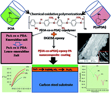
The formation of the iron oxide layer at the coating metal interface improved the corrosion protection by the dispersion of the copolymer in coatings. The presence of the passive layer was confirmed by the Raman spectra. As shown in Fig. 13, the bands that appeared due to the surface of the P(oA-co-oPDA)-epoxy-PA copolymer and epoxy-PA coated CS samples being immersed for 15 days in 5 wt% NaCl aqueous solution were investigated. The presence of the peak at 526 cm−1 was assigned to the chlorination of P(oA-co-o-PDA)-epoxy-PA, the absence of such modification in the epoxy without the conducting polymer filler may be an indication of the observed structural changes induced by the filler in the epoxy and these changes improve the corrosion protection performance, as also reported in the literature. The detailed assignment of the peaks is shown in Table 5. The bands at about 216, 281, and 1293 cm−1 were assigned to α-Fe2O3 (Fig. 13). This indicates that the surface of CS coated by P(oA-co-oPDA)-epoxy-PA formed a passive layer of α-Fe2O3. Furthermore, Raman spectroscopy also depicted some kind of interaction between the epoxy matrix and the P(oA-co-o-PDA) copolymer filler. During the immersion in media the oxidation of Fe to Fe2+ and Fe3+ takes place through the formation of the passive oxide layer. In this case, the oxidation was accompanied by the reduction of PoA-co-o-PDA-ES (emeraldine salt) to PoA-co-o-PDA-LS (leuco-emeraldine salt) forming a passive layer and this follows the mechanism of PANI. Because of this passive layer, the copolymer coatings were able to offer high corrosion resistance, as evident from the EIS studies. Here, in the case of the P(oA-co-o-PDA)-epoxy-PA coatings the presence of the P(oA-co-oPDA) copolymer in the epoxy matrix acts as a barrier with a two step mechanism. Moreover, as PoA copolymerizes with PoPDA, which is a ladder polymer with a molecular structure of a phenazine skeleton along with an asymmetrical quinoid structure, it ensures a greater adsorption of the copolymer in the epoxy-PA matrix on the CS surface. It also decreased the effective area for the corrosion reaction by blocking the reaction sites and the presence of pi electrons in the aromatic ring co-existing with the quaternary nitrogen atom.20 Anodically produced Fe3+ ions form a metal coordinate ligand with the heteroatoms (nitrogen and oxygen) present in PoPD. Subsequently, the cathodic reaction was suppressed due to the lack of electrons. Moreover, the conductivity of the copolymer layer affects the oxidative tendency, which brought about the passive state. Furthermore, the excellent adhesion of the P(oA-co-o-PDA)-epoxy-PA nanocomposite coatings with the metal substrate is due to the uniform dispersion of the P(oA-co-oPDA) nanoparticles in the matrix as is evident from the SEM/EDX study (Fig. 12b). This can help support the superior anti-corrosive performance. Based on these observations, a suitable mechanism has been presented in the graphical abstract.
 |
| Fig. 12 (a) SEM-EDAX of plain epoxy coating. (b) SEM/EDAX of P(oA-co-o-PDA)-epoxy-PA nanocomposite coatings. | |
 |
| Fig. 13 Raman spectra of epoxy-PA coated and P(oA-co-o-PDA)-epoxy-PA coated CS after SST. | |
Table 5 Raman bands assignments for nanocomposite coatings
Band position (cm−1) |
Assignments |
1605 |
C–C stretching vibration of aromatics; C–O stretching vibration of amides; skeletal vibrations of C–C double bonds in aromatic ring |
1220 |
C–O stretching vibration of ether bridges, C–O stretching vibration of secondary alcohols |
987 |
Epoxy group |
657 |
Aromatic ring vibrations (o-substituted benzene); aromatic C–H out of plane deformation |
216, 281 and 1293 |
Are assigned to Fe2O3 showing the formation of a passive layer |
4. Conclusion
P(oA-co-oPDA) nanorods and PoA nanoparticles were synthesized via emulsion polymerization and their nanocomposites were prepared using an epoxy-PA matrix by a solution blending method. The P(oA-co-oPDA) copolymer nanorods were characterized by FTIR, 1H-NMR, XRD, UV-visible, SEM and TEM. The nanocomposite coatings exhibited enhanced physico-mechanical properties in comparison to a virgin epoxy and bare CS, owing to a uniform dispersion of the nanostructures in the epoxy matrix. The contact angle, salt spray test, and potentiodynamic polarization revealed that P(oA-co-oPDA)-epoxy-PA acted as a hydrophobic and protective coating on CS against corrosion in NaCl and HCl media (5 wt%). Raman spectroscopy revealed the presence of a passive ferric oxide layer, which induces a remarkable effect in the P(oA-co-oPDA)-epoxy-PA composite coatings. These studies revealed that the nanocomposite coatings exhibited outstanding anti-corrosive properties when compared to other such reported CP based coatings. Further studies, such as the effect of pH, are ongoing.
Acknowledgements
Neha Kanwar Rawat is thankful to the University Grants Commission (UGC-BSR), New Delhi, India, for financial support in this work. Authors also acknowledge to SAIF centre, All India institute of Medical Science (AIIMS) and AIRF, Jawaharlal Nehru University, New Delhi. The authors are grateful for the TGA facility under the UGC, SAP of the Department of Chemistry, JMI, and New Delhi, India.
References
- T. Tüken, B. Yazıcı and M. Erbil, Prog. Org. Coat., 2005, 53, 38–45 CrossRef.
- Y. Chen, X. H. Wang, J. Li, J. L. Lu and F. S. Wang, Corros. Sci., 2007, 49, 3052–3063 CrossRef CAS.
- R. Arefinia, A. Shojaei, H. Shariatpanahi and J. Neshati, Prog. Org. Coat., 2012, 75, 502–508 CrossRef CAS.
- A. G. MacDiarmid, Synth. Met., 2001, 125, 11–22 CrossRef.
- S. Bhadra, D. Khastgir, N. K. Singha and J. H. Lee, Prog. Polym. Sci., 2009, 34, 783–810 CrossRef CAS.
- H. D. Tran and R. B. Kaner, Chem. Commun., 2006, 3915–3917 RSC.
- U. Riaz, R. Jahan, S. Ahmad and S. M. Ashraf, J. Appl. Polym. Sci., 2008, 108, 2604–2610 CrossRef CAS.
- P. A. Kilmartin, L. Trier and G. A. Wright, Synth. Met., 2002, 131, 99–109 CrossRef CAS.
- T. D. Nguyen, T. A. Nguyen, M. C. Pham, B. Piro, B. Normand and H. Takenouti, J. Electroanal. Chem., 2004, 572, 225–234 CrossRef CAS.
- R. Jadhav, D. Hundiwale and P. Mahulikar, J. Coat. Technol. Res., 2010, 7, 449–454 CrossRef CAS.
- S. Chaudhari and P. P. Patil, Electrochim. Acta, 2007, 53, 927–933 CrossRef CAS.
- B. Yao, G. Wang, X. Li and Z. Zhang, J. Appl. Polym. Sci., 2009, 112, 1988–1993 CrossRef CAS.
- P. Fu, H. Li, J. Sun, Z. Yi and G.-C. Wang, Prog. Org. Coat., 2013, 76, 589–595 CrossRef CAS.
- F. Chen and P. Liu, ACS Appl. Mater. Interfaces, 2011, 3, 2694–2702 CAS.
- M. Mobin and N. Tanveer, J. Coat. Technol. Res., 2012, 9, 27–38 CrossRef CAS.
- N. Tanveer and M. Mobin, J. Miner. Mater. Charact. Eng., 2011, 10, 735 Search PubMed.
- P. Fu, H. Li, J. Sun, Z. Yi and G.-C. Wang, Prog. Org. Coat., 2013, 76, 589–595 CrossRef CAS.
- S. Pathan and S. Ahmad, J. Mater. Chem. A, 2013, 1, 14227–14238 CAS.
- Y. Liu, D. Sun, H. You and J. S. Chung, Appl. Surf. Sci., 2005, 246, 82–89 CrossRef CAS.
- P. Muthirulan and N. Rajendran, Surf. Coat. Technol., 2012, 206, 2072–2078 CrossRef CAS.
- M. Kashif and S. Ahmad, RSC Adv., 2014, 4, 20984–20999 RSC.
- S. Ahmad, U. Riaz, M. Kashif and M. Khan, J. Inorg. Organomet. Polym. Mater., 2012, 22, 662–670 CrossRef CAS.
- E. P. Koval’chuk, N. V. Stratan, O. V. Reshetnyak, J. Błażejowski and M. S. Whittingham, Solid State Ionics, 2001, 141–142, 217–224 CrossRef.
- T. Siva, K. Kamaraj, V. Karpakam and S. Sathiyanarayanan, Prog. Org. Coat., 2013, 76, 581–588 CrossRef CAS.
- A. C. C. de Leon, R. B. Pernites and R. C. Advincula, ACS Appl. Mater. Interfaces, 2012, 4, 3169–3176 CAS.
- O. U. Rahman, S. C. Mohapatra and S. Ahmad, Mater. Chem. Phys., 2012, 132, 196–202 CrossRef CAS.
- Y. Jafari, M. Shabani-Nooshabadi and S. M. Ghoreishi, Polym. Adv. Technol., 2014, 25, 279–287 CrossRef CAS.
- S. J. Lee, J. M. Lee, I. W. Cheong, H. Lee and J. H. Kim, J. Polym. Sci., Part A: Polym. Chem., 2008, 46, 2097–2107 CrossRef CAS.
- B.-J. Kim, S.-G. Oh, M.-G. Han and S.-S. Im, Synth. Met., 2001, 122, 297–304 CrossRef CAS.
- W.-S. Huang, B. D. Humphrey and A. G. MacDiarmid, J. Chem. Soc., Faraday Trans. 1, 1986, 82, 2385–2400 RSC.
- S. Palraj, M. Selvaraj, M. Vidhya and G. Rajagopal, Prog. Org. Coat., 2012, 75, 356–363 CrossRef CAS.
- N. K. Rawat, A. Ghosal and S. Ahmad, RSC Adv., 2014, 4, 50594–50605 RSC.
- A. K. Dewan, D. P. Valenzuela, S. T. Dubey and A. K. Dewan, Ind. Eng. Chem. Res., 2002, 41, 914–921 CrossRef CAS.
- M. Wang, H. Zhang, C. Wang, X. Hu and G. Wang, Electrochim. Acta, 2013, 91, 144–151 CrossRef CAS.
- N. Pirhady Tavandashti, S. Sanjabi and T. Shahrabi, Prog. Org. Coat., 2009, 65, 182–186 CrossRef CAS.
- H. Wei, D. Ding, S. Wei and Z. Guo, J. Mater. Chem. A, 2013, 1, 10805–10813 CAS.
- S. V. Lamaka, M. F. Montemor, A. F. Galio, M. L. Zheludkevich, C. Trindade, L. F. Dick and M. G. S. Ferreira, Electrochim. Acta, 2008, 53, 4773–4783 CrossRef CAS.
- H. Zhang, J. Wang, X. Liu, Z. Wang and S. Wang, Ind. Eng. Chem. Res., 2013, 52, 10172–10180 CrossRef CAS.
- S. V. Lamaka, M. L. Zheludkevich, K. A. Yasakau, R. Serra, S. K. Poznyak and M. G. S. Ferreira, Prog. Org. Coat., 2007, 58, 127–135 CrossRef CAS.
- İ. Çakmakcı, B. Duran and G. Bereket, Prog. Org. Coat., 2013, 76, 70–77 CrossRef.
- T. P. Chou, C. Chandrasekaran, S. J. Limmer, S. Seraji, Y. Wu, M. J. Forbess, C. Nguyen and G. Z. Cao, J. Non-Cryst. Solids, 2001, 290, 153–162 CrossRef CAS.
- J. Fu, T. Chen, M. Wang, N. Yang, S. Li, Y. Wang and X. Liu, ACS Nano, 2013, 7, 11397–11408 CrossRef CAS PubMed.
- M. Wang, M. Liu and J. Fu, J. Mater. Chem. A, 2015, 3, 6423–6431 CAS.
- J. N. Murray, L. D. Stephenson and A. Kumar, Prog. Org. Coat., 2003, 47, 136–146 CrossRef CAS.
- A. Kumar, L. D. Stephenson and J. N. Murray, Prog. Org. Coat., 2006, 55, 244–253 CrossRef CAS.
- P. J. Kinlen, D. C. Silverman and C. R. Jeffreys, Synth. Met., 1997, 85, 1327–1332 CrossRef CAS.
Footnote |
† Electronic supplementary information (ESI) available. See DOI: 10.1039/c5ra14590b |
|
This journal is © The Royal Society of Chemistry 2015 |
Click here to see how this site uses Cookies. View our privacy policy here.