DOI:
10.1039/C5RA14477A
(Paper)
RSC Adv., 2015,
5, 78910-78916
Coro-graphene and circumcoro-graphyne: novel two-dimensional materials with exciting electronic properties†
Received
22nd July 2015
, Accepted 7th September 2015
First published on 8th September 2015
Abstract
In this study, two novel forms of two-dimensional (2D) carbon frameworks (named as coro-graphene (CG) and circumcoro-graphyne (CCG)) were designed with the help of First-Principles Density Functional Theory based calculations using the PBE-GGA level of theory employing a plane wave basis set. Both CG and CCG exhibit the space group p6/mmm which is akin to that of graphene. The dynamical stability of CG and CCG was analyzed by performing phonon mode analysis and molecular dynamics simulations. Interestingly, the CG shows a narrow band gap. Anisotropic Dirac cones in the proximity of the Fermi level are observed in the case of CCG. The band gap and other associated features of these novel 2D materials are sensitive to the external strain and hole/electron doping (B/N doping).
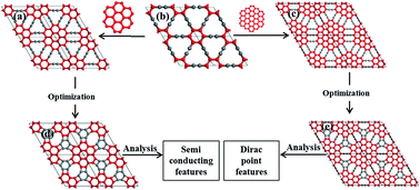
1. Introduction
The design and synthesis of novel two-dimensional (2D) materials have attracted the attention of researchers1–3 as they cover a wide range of technological applications in various fields.4–11 Primarily, investigations on 2D materials have been inspired by the successful exfoliation12 and outstanding application potentials of graphene.13 The existence of the Dirac point or Dirac cones14 in the electronic band structure is a very important feature of graphene. The physics of the Dirac point is the central topic in condensed-matter physics, as it is responsible for the many intriguing phenomena including massless15 and massive16 Dirac fermions, half-integer quantum Hall effect,17 Klein tunneling,18 pseudo-diffusive conduction19 and conducting edge states20,21 in topological insulators. The Dirac point arises due to the linear relationship between the energy (E) of a hole and electron with the wave vector (K) that results cone-like bands nearer to the Fermi level. These cones are commonly known as Dirac cones and their degenerate point nearer to the Fermi level is referred to as so called Dirac point. Numerous theoretical and experimental studies have been reported in the literature which authenticate the prominence of Dirac point. For instance, the elemental allotropes of graphene such as graphynes,22 five-, six- and seven-membered carbon sheets,23 T-graphene,24 silicene25 and germanene26,27 have been studied with the perspective to unravel Dirac-like dispersion relations.
However, in the recent times graphynes22,28,29 have gained wide-spread attention30 among all other carbon allotropes due to their accessibility to the experimental fabrication and some superior characteristics31 over graphene. The carbon frameworks that possess sp- as well as sp2-hybridized carbon atoms are generally called as graphynes.32 By varying the ratio of sp- and sp2-hybridized carbon atoms, different forms of graphyne architectures have been created including the popularly known α-, β-, γ-, δ- and 6,6,12-graphyne. For instance, the α-, β- and γ-graphyne are created by insertion a triple bond (acetylenic linker) in all the C–C bond, two-thirds of the C–C bonds and one-third of the C–C bonds of graphene, respectively.28 In spite of their different architectures, all the forms of aforementioned graphynes have Dirac cone like band structures except γ-graphyne. The previous studies show that γ-graphyne exhibits a direct band gap of ∼0.47 eV, which is attributed to the Peierls instability occurring in a 2D frame work.28 In γ-graphyne, the benzene rings are joined to another benzene by six C–C triple bonds. The successive addition of triple bonds (sp-hybridized carbon atoms) between the benzene rings further opens the band gap.33 It is interesting to explore how does the increase in sp2-network around the benzene ring influence electronic structure of γ-graphyne. Conceivably, the extra π-conjugation may close the small direct band gap and probably leads to the Dirac like band structure. However, it is interesting to explore the electronic structure and band gap of the novel 2D systems.
The above-mentioned changes arise due to extension of π-conjugation around benzene in graphyne have motivated to design two novel planar 2D materials comprising sp- and sp2-hybridized carbon atoms using First-Principles DFT approach. These novel 2D materials are christened as coro-graphene (CG) and circumcoro-graphyne (CCG). Results show that CG is a narrow band gap semiconductor, while CCG is a semimetal with direction dependent Dirac cones.
2. Computational details
All density functional theory (DFT) based non spin polarized and spin polarized (for doped ssytems) calculations were carried out using Vienna ab initio Simulation Package34–36 (VASP). The generalized gradient approximation (GGA) parameterized by Perdew–Burke–Ernzerhof (PBE)37 was included to calculate the exchange and correlation energy. The all-electron projector augmented wave (PAW)38 method was adopted with carbon 2s22p2 treated as valence electrons. The plane waves were extended with a kinetic energy cutoff of 520 eV. The energy minimization was performed using the conjugate gradient iterative technique with a Monkhorst–Pack39 of 4 × 4 × 1 k-mesh in the Brillouin zone until the energy between two consecutive steps was less than 10−5 eV and the Hellmann–Feynman force was less than 0.01 eV per atom. The electronic band structure calculations were carried out with a denser Monkhorst–Pack of 8 × 8 × 1 k-points. The density of states was calculated using the tetrahedron method with Blochl corrections.40 The phonon band dispersion curves of the 2D carbon sheets were plotted using the open source package Phonopy.41 The dynamic stability of the 2D materials was also examined by performing DFT based molecular dynamics (MD) simulations.
3. Results and discussion
The CG and CCG were derived from γ-graphyne by replacing each of its benzene ring with a coronene and circumcoronene frameworks, respectively. The optimized geometries of γ-graphyne, intermediate structures, coro-graphene (CG) and circumcoro-graphyne (CCG) are presented in Fig. 1. The coronene (circumcoronene) units were joined to one another by 12 (18) acetylenic linkers, which results the intermediate structure of CG (CCG) as shown in Fig. 1a and c. These intermediate structures are dynamically not stable as they possess imaginary frequencies in the phonon band spectrum. The following structural relaxation to remove the negative frequencies of these intermediate structures leads to the stable 2D planar carbon architectures. The newly designed CG and CCG are depicted in Fig. 1d and e, respectively. Both CG and CCG exhibit the hexagonal space group (p6/mmm) which is similar to that of graphene. The optimized lattice constant a of CG (CCG) is equal to b. It is found to be 11.05 Å for CG and 15.37 Å for CCG. The unit cell of CG contains 36 carbon atoms. On the other hand the same of CCG has 72 carbon atoms. The carbon atoms occupy four inequivalent Wyckoff positions in the unit cell of CG, while eight inequivalent Wyckoff positions in the unit cell of CCG. All the atomic coordinates are given in ESI in Fig. S1.† The CG and CCG exhibit different bond lengths in which the C–C triple bond length is equal to ∼1.21 Å. The C–C double bond ranges from 1.38–1.48 Å. The sp bond angle is around 180° and the sp2 bond angles ranges from 88–152°. The slight deviation from the ideal sp and sp2 bond parameters leads to the ring strain in both CG and CCG. Obviously, this raises concern on the stability of CG and CCG. Hence, the dynamical stabilities of both CG and CCG have been investigated by performing First Principle MD simulations and also by evaluating the phonon band dispersion relations. It can be seen from Fig. 2 that, all the phonon modes of both the forms of 2D carbon materials are free from imaginary frequencies throughout the Brillouin zone, suggesting that CG and CCG are dynamically stable. Even though CG and CCG were consists of same kind of atoms, CCG possess highest frequency phonon modes at ∼2300 cm−1 which were not found in the phonon band spectrum of CG. These highest frequency normal modes of CCG are due to the symmetrical stretching of central C–C triple bond, which is absent in the case of CG. Results from the First-Principles MD simulation at 300 K for 5 ps with a time step of 1 fs using NVT ensemble are plotted for CG and CCG in Fig. 3. It reveals that the mean value of total energy is nearly constant throughout the simulation and after 5000 steps there are no substantial deformations in the geometries of CG and CCG. These results suggest that, the CG and CCG are thermodynamically stable. The MD simulations were also carried out on CG and CCG for 9 ps. However, there are no substantial changes in the results as shown in Fig. S2 (ESI†). Furthermore, we analyzed the relative stabilities of other 2D materials which are obtained by joining the linkers of CG and CCG in various ways. However all these structures are energetically not favorable when compared to CG and CCG and the results are presented in Fig. S3 (ESI†).
 |
| Fig. 1 Creation of coro-graphene and circumcoro-graphyne from γ-graphyne by replacing benzene ring with coronene and circumcoronene. The optimized geometries of 2 × 2 × 1 supercell of (b) γ-graphyne (d) coro-graphene (e) circumcoro-graphyne and (a) and (c) are intermediate structures (carbon atoms are represented in red and grey colors for clarity). | |
 |
| Fig. 2 Calculated phonon band spectra of (a) coro-graphene and (b) circumcoro-graphyne along the high symmetric points in the Brillouin zone. | |
 |
| Fig. 3 Total energy fluctuation of (a) CG and (b) CCG at 300 K. | |
The calculated electronic band structures of CG are presented in Fig. 4. The CG is a direct and narrow band gap semiconductor. Both the highest occupied valence band (HOVB) maximum and lowest unoccupied conduction band (LUCB) minimum are located at the same asymmetric point Θ (−0.095, 0.548, 0.000) between the high-symmetry k-points M and K as shown in Fig. 4a and b. The calculated band gap of CG is found to be ∼0.63 eV at the present level of theory. Generally, the PBE-GGA level of theory underestimates the band gap of the periodic structures. Hence, we have calculated the band gap with the hybrid-density functional theory proposed by Heyd, Scuseria and Ernzerhof in 2006 such as HSE06 to predict the band gap more accurately. The estimated band gap using this functional is ∼0.86 eV. The calculated total and partial density of states of CG are given in Fig. 4c. It is clearly evident that the pz bonding and anti-bonding states of carbon atom are primarily responsible for the formation of valence and conduction bands nearer to the Fermi level. In addition to this, the energy gap in the DOS panel is also consistent with estimated band gap of CG at the PBE-GGA level of theory. These results reinforces that the CG is a narrow band gap semiconductor.
 |
| Fig. 4 Calculated electronic band structures of coro-graphene. (a) Full band structure for a unit cell and the inset represents the first Brillouin zone with the high symmetry k-points along which the bands are plotted (b) amplification of bands around minimum band gap and (c) density of states (the Fermi level is set as 0 eV in all cases). | |
The calculated electronic band structures of CCG are shown in Fig. 5. The HOVB and LUCB of CCG meet in a single point at the Fermi level as presented in Fig. 5a. Both HOVB and LUCB approach their meeting point with a slope (first derivative of band energies) of ±18 eV Å from Γ and ±10 eV Å from M. Meanwhile, the same bands exhibits a curvature (second derivative of band energies) of ±471 and ±1292 eV Å2 along a line from Γ and M to the meeting point, respectively. On the other hand, the HOVB and LUCB approach their meeting point with a slope of ±18 eV Å and zero curvature along a line which is perpendicular to the Γ–M line. Furthermore, the three dimensional plot of HOVB and LUCB exhibits a double cone feature around the meeting point as shown in Fig. 5c. These are the characteristic band features22 of Dirac like dispersion and thus the meeting point of HOVB and LUCB of CCG can be referred to as Dirac point in this new 2D sheet. Further, the CCG exhibits six Dirac points in the complete Brillouin zone similar to that of β-graphyne.22 However, the six Dirac points are symmetry related by rotation of the Brillouin zone in steps of 60° and the double cones at each Dirac point exhibit reflection symmetry with respect to the Γ–M line (see the inset in Fig. 5a). Hence, among the six Dirac points, only one is independent which is located at an asymmetric position (0.000, 0.395, 0.000) on the line segment Γ to M as shown in Fig. 5b and c.
 |
| Fig. 5 Calculated electronic band structures of circumcoro-graphyne. (a) Full band structure for a unit cell and the inset represents the first Brillouin zone with the high symmetry k-points along which the bands are plotted (b) amplification of bands around the Dirac point and (c) the three-dimensional band structure at the Dirac point (the Fermi level is set as 0 eV in all cases). | |
To obtain deeper insight into the bonding and anti-bonding orbitals which are responsible for the formation of Dirac point, the DOS and the partial charge densities corresponding to HOVB and LUCB of CCG were calculated. It can be seen from the DOS panel (Fig. 6a) that the HOVB and LUCB are completely formed from the pz bonding and antibonding orbitals of carbon atom, respectively. Further, the partial charge densities (Fig. 6b and c) corresponding to HOVB and LUCB reveals that, the carbon atoms which are at the periphery of the circumcoronene unit of CCG sheet are mainly contributed for the formation of HOVB and LUCB among the other carbon atoms of the CCG sheet.
 |
| Fig. 6 Calculated (a) density of states and partial charge density corresponding to (b) HOVB and (c) LUCB of cirucumcoro-graphyne. The charge densities are plotted for an isosurfaces value of 0.002 e per Bhor3. | |
Further, the effect of hole or electron doping (by B or N atom) and the application of uniform strain (ε) on the electronic properties of CG and CCG have been investigated. The CG is doped with either B or N atom at 4 different sites of C atom as shown in Fig. 7a. It can be seen from Fig. 7b that, the hole doping (B doping) shifts the valence band (HOVB) above the Fermi level. The shifting of conduction band (LUCB) below the Fermi level can be seen for the electron doping (N doping) in Fig. 7c. However, there are no considerable changes in the band profiles of B or N doped CG with respect different doping sites. The representative band structures for B and N doped CG at four different carbon sites are depicted in Fig. 7b and c, respectively. Similarly, the CCG is also doped with B and N atoms at 8 different carbon sites as shown in Fig. 7d. The anisotropic Dirac properties of CCG are completely removed by the B or N doping. The HOVB and LUCB of undoped CCG are slightly shifted above and below the Fermi level upon the external doping of B and N atoms, respectively. Fig. 7e and f, respectively show the representative band structures for B and N doped CCG at various sites. Similar to the CG, there are no substantial changes in the band profiles of CCG based on the site to site doping. It is important to mention here that, the up and down spin bands are completely degenerate for most of the doping sites in both (CG, CCG) cases. The degenerate and non-degenerate band structures for all doping sites of CG and CCG are presented in Fig. S4 and S5 (ESI†).
 |
| Fig. 7 (a) Different doping sites of CG (b) B doped band structure of CG (c) N doped band structure of CG and (d) different doping sites of CCG (e) B doped band structure of CCG (f) N doped band structure of CCG. The curved red and black dotted lines represent up and down spin bands. The band structures are taken for second doping site in all the cases. | |
The strain can be applied on the graphene-like or any 2D materials in various ways including lattice mismatch between the target 2D material and supporting substrate,42 maintaining difference in thermal expansion coefficient between the 2D materials and substrate,43,44 atomic force microscope technique,45 material doping,46 mechanical loading,47 functional wrapping48 and the formation of ridges and buckling in 2D lattices.49 Theoretically, the uniform strain is applied by varying the lattice constant (a) of unit cell of CG and CCG as defined by ε = (as − a)/a × 100%, where a and as are the equilibrium and strained lattice constants. The strain value is altered from −10% to +10% in steps of 1% for both CG and CCG. The variation of band gap of CG with respect to external uniform strain is depicted in Fig. 8. The direct band gap of CG is steadily decreased in the compressive strain range (−1% to −10%). It exhibits a lowest band gap of 0.29 eV at ε = −10%. In addition to this, the direct band gap of unstrained CG at the k-point Θ (−0.095, 0.548, 0.000) moves to high symmetry k-point M (0.00, 0.05, 0.00) in the strain range ε = −2 to −10%. While, the tensile strain on CG increases the band gap. The direct band gap of CG is sustained up to the ε = 4% and transformed to indirect band gap on further application of uniform tensile strain. The CG has an indirect band gap of 1.21 eV at the extreme of applied tensile strain range. The effect of applied strain on the electronic structure of CCG is also given in Fig. 8. It shows that the applied compressive strain has little impact on electronic structure of CCG. While, the tensile strain on CCG makes it as a direct band gap semiconductor. The direct band gap of CCG increases with the applied tensile strain. The direct band gap shifts from the asymmetric position (0.000, 0.395, 0.000) to a high symmetry k-point M at ε = 3%. The CCG exhibits a band gap of 0.42 eV at the applied tensile strain ε = 10%. Hence, these materials may have wide applications in the future semiconducting devices as the band gaps are tunable by the employment of strain and external doping.
 |
| Fig. 8 Calculated electronic band gaps of CG and CCG under the applied strain. | |
4. Conclusions
In this study, two novel two-dimensional (2D) carbon allotropes have been designed using coronene and circumcoronene units with the aid of the state-of-the-art theoretical calculations. The inspection on thermal and dynamical properties of the novel 2D materials discloses the stability of CG and CCG. The electronic structure calculations revels that, CG is a narrow band gap direct semiconductor and CCG is a zero-band gap Dirac material. The electronic features of CG and CCG are perturbed by the hole or electron doping and also influenced by the applications of strain. These two 2D materials can be effectively exploited in the development of novel semi-conducting devices.
Acknowledgements
The authors acknowledge the Multi-Scale Simulation and Modelling (MSM) project (CSC0129), CSIR and DST (ref. no. EMR/2015/000447) for financial support.
References
- K. S. Novoselov, D. Jiang, F. Schedin, T. J. Booth, V. V Khotkevich, S. V Morozov and a K. Geim, Proc. Natl. Acad. Sci. U. S. A., 2005, 102, 10451–10453 CrossRef CAS PubMed.
- V. Nicolosi, M. Chhowalla, M. G. Kanatzidis, M. S. Strano and J. N. Coleman, Science, 2013, 340, 1226419–1226518 CrossRef.
- P. Miro, M. Audiffred and T. Heine, Chem. Soc. Rev., 2014, 43, 6537–6554 RSC.
- K. C. Kemp, H. Seema, M. Saleh, N. H. Le, K. Mahesh, V. Chandra and K. S. Kim, Nanoscale, 2013, 5, 3149–3171 RSC.
- Y. Huang, J. Liang and Y. Chen, Small, 2012, 8, 1805–1834 CrossRef CAS PubMed.
- L. Feng, L. Wu and X. Qu, Adv. Mater., 2013, 25, 168–186 CrossRef CAS PubMed.
- D. Lembke, S. Bertolazzi and A. Kis, Acc. Chem. Res., 2015, 48, 100–110 CrossRef CAS PubMed.
- Y. Zheng, Y. Jiao, J. Chen, J. Liu, J. Liang, A. Du, W. Zhang, Z. Zhu, S. C. Smith, M. Jaroniec, G. Q. (Max) Lu and S. Z. Qiao, J. Am. Chem. Soc., 2011, 133, 20116–20119 CrossRef CAS PubMed.
- S. Z. Butler, S. M. Hollen, L. Cao, Y. Cui, J. A. Gupta, H. R. Gutie, T. F. Heinz, S. S. Hong, J. Huang, A. F. Ismach, E. Johnston-halperin, M. Kuno, V. V. Plashnitsa, R. D. Robinson, R. S. Ruoff, S. Salahuddin, J. Shan, L. Shi, M. G. Spencer, M. Terrones, W. Windl and J. E. Goldberger, ACS Nano, 2013, 7, 2898–2926 CrossRef CAS PubMed.
- C. R. Dean, A. F. Young, I. Meric, C. Lee, L. Wang, S. Sorgenfrei, K. Watanabe, T. Taniguchi, P. Kim, K. L. Shepard and J. Hone, Nat. Nanotechnol., 2010, 5, 722–726 CrossRef CAS PubMed.
- D. Jariwala, V. K. Sangwan, L. J. Lauhon, T. J. Marks and M. C. Hersam, ACS Nano, 2014, 8, 1102–1120 CrossRef CAS PubMed.
- K. S. Novoselov, A. K. Geim, S. V Morozov, D. Jiang, Y. Zhang, S. V Dubonos, I. V Grigorieva and A. A. Firsov, Science, 2004, 306, 666–669 CrossRef CAS PubMed.
- K. S. Novoselov, A. K. Geim, S. V Morozov, D. Jiang, M. I. Katsnelson, I. V Grigorieva, S. V Dubonos and A. A. Firsov, Nature, 2005, 438, 197–200 CrossRef CAS PubMed.
- A. H. Castro Neto, F. Guinea, N. M. R. Peres, K. S. Novoselov and A. K. Geim, Rev. Mod. Phys., 2009, 81, 109–162 CrossRef CAS.
- M. Orlita, D. M. Basko, M. S. Zholudev, F. Teppe, W. Knap, V. I. Gavrilenko, N. N. Mikhailov, S. A. Dvoretskii, P. Neugebauer, C. Faugeras, A.-L. Barra, G. Martinez and M. Potemski, Nat. Phys., 2014, 10, 233–238 CrossRef CAS PubMed.
- B. Hunt, J. D. Sanchez-Yamagishi, A. F. Young, M. Yankowitz, B. J. LeRoy, K. Watanabe, T. Taniguchi, P. Moon, M. Koshino, P. Jarillo-Herrero and R. C. Ashoori, Science, 2013, 340, 1427–1430 CrossRef CAS PubMed.
- Y. Zhang, Y.-W. Tan, H. L. Stormer and P. Kim, Nature, 2005, 438, 201–204 CrossRef CAS PubMed.
- M. I. Katsnelson, K. S. Novoselov and A. K. Geim, Nat. Phys., 2006, 2, 620–625 CrossRef CAS PubMed.
- A. R. Akhmerov and C. W. J. Beenakker, Phys. Rev. B: Condens. Matter Mater. Phys., 2007, 75, 045426 CrossRef.
- X.-L. Qi and S.-C. Zhang, Rev. Mod. Phys., 2011, 83, 1057–1110 CrossRef CAS.
- M. Z. Hasan and C. L. Kane, Rev. Mod. Phys., 2010, 82, 3045–3067 CrossRef CAS.
- D. Malko, C. Neiss, F. Vin and A. Gorling, Phys. Rev. Lett., 2012, 108, 086804 CrossRef.
- L.-C. Xu, R.-Z. Wang, M.-S. Miao, X.-L. Wei, Y.-P. Chen, H. Yan, W.-M. Lau, L.-M. Liu and Y.-M. Ma, Nanoscale, 2014, 6, 1113–1118 RSC.
- Y. Liu, G. Wang, Q. Huang, L. Guo and X. Chen, Phys. Rev. Lett., 2012, 108, 225505 CrossRef.
- L. Chen, C.-C. Liu, B. Feng, X. He, P. Cheng, Z. Ding, S. Meng, Y. Yao and K. Wu, Phys. Rev. Lett., 2012, 109, 56804 CrossRef.
- S. Trivedi, A. Srivastava and R. Kurchania, J. Comput. Theor. Nanosci., 2014, 11, 781–788 CrossRef CAS PubMed.
- M. E. Dávila, L. Xian, S. Cahangirov, A. Rubio and G. L. Lay, New J. Phys., 2014, 16, 95002 CrossRef.
- B. G. Kim and H. J. Choi, Phys. Rev. B: Condens. Matter Mater. Phys., 2012, 86, 115435 CrossRef.
- W.-J. Yin, Y.-E. Xie, L.-M. Liu, R.-Z. Wang, X.-L. Wei, L. Lau, J.-X. Zhong and Y.-P. Chen, J. Mater. Chem. A, 2013, 1, 5341 CAS.
- Z. Li, M. Smeu, A. Rives, V. Maraval, R. Chauvin, M. A. Ratner and E. Borguet, Nat. Commun., 2015, 6, 6321 CrossRef CAS PubMed.
- M. Zhao, W. Dong and A. Wang, Sci. Rep., 2013, 3, 3532 Search PubMed.
- R. H. Baughman, H. Eckhardt and M. Kertesz, J. Chem. Phys., 1987, 87, 6687–6699 CrossRef CAS PubMed.
- Q. Yue, S. Chang, J. Kang, S. Qin and J. Li, J. Phys. Chem. C, 2013, 117, 14804–14811 CAS.
- G. Kresse and J. Furthmüller, Phys. Rev. B: Condens. Matter Mater. Phys., 1996, 54, 11169–11186 CrossRef CAS.
- G. Kresse and J. Furthmüller, Comput. Mater. Sci., 1996, 6, 15–50 CrossRef CAS.
- MedeA-VASP (Materials Design Inc.) is a commercial pack that provides a graphical interface to set up, run, and analyze VASP calculations under the Windows environment.
- J. P. Perdew, K. Burke and M. Ernzerhof, Phys. Rev. Lett., 1996, 77, 3865–3868 CrossRef CAS.
- P. E. Blöchl, Phys. Rev. B: Condens. Matter Mater. Phys., 1994, 50, 17953–17979 CrossRef.
- H. J. Monkhorst and J. D. Pack, Phys. Rev. B: Solid State, 1976, 13, 5188–5192 CrossRef.
- P. E. Blöchl, O. Jepsen and O. K. Andersen, Phys. Rev. B: Condens. Matter Mater. Phys., 1994, 49, 16223–16233 CrossRef.
- A. Togo, F. Oba and I. Tanaka, Phys. Rev. B: Condens. Matter Mater. Phys., 2008, 78, 134106 CrossRef.
- M. L. Teague, A. P. Lai, J. Velasco, C. R. Hughes, A. D. Beyer, M. W. Bockrath, C. N. Lau and N.-C. Yeh, Nano Lett., 2009, 9, 2542–2546 CrossRef CAS PubMed.
- N. Ferralis, R. Maboudian and C. Carraro, Phys. Rev. Lett., 2008, 101, 156801–156804 CrossRef.
- W. Pan, J. Xiao, J. Zhu, C. Yu, G. Zhang, Z. Ni, K. Watanabe, T. Taniguchi, Y. Shi and X. Wang, Sci. Rep., 2012, 2, 893–896 Search PubMed.
- C. Lee, X. Wei, J. W. Kysar and J. Hone, Science, 2008, 321, 385–388 CrossRef CAS PubMed.
- L. Seravalli, M. Minelli, P. Frigeri, P. Allegri, V. Avanzini and S. Franchi, Appl. Phys. Lett., 2003, 82, 2341–2343 CrossRef CAS PubMed.
- M. Aoki, H. Kawanowa, G. Feng and T. Kimoto, Jpn. J. Appl. Phys., 2013, 52, 061301–061305 CrossRef.
- A. Thean and J. P. Leburton, Appl. Phys. Lett., 2001, 79, 1030 CrossRef CAS PubMed.
- Y. Cai, A. Zhang, Y. P. Feng, C. Zhang, H. F. Teoh and G. W. Ho, J. Chem. Phys., 2009, 131, 224701 CrossRef PubMed.
Footnote |
† Electronic supplementary information (ESI) available: The different atomic Wyckoff positions, MD simulations results, relative energies of other 2D materials, B or N doped band structures. See DOI: 10.1039/c5ra14477a |
|
This journal is © The Royal Society of Chemistry 2015 |
Click here to see how this site uses Cookies. View our privacy policy here.