Mechanism and kinetic study on the ring-opening degradation of 2,3,7,8-tetrachlorinated dibenzofuran initiated by OH radicals in waste incineration

Kun Zhanga, Shengmin Sunb and Hui Zhang*a
aCollege of Chemical and Environmental Engineering, Harbin University of Science and Technology, Harbin 150080, P. R. China. E-mail: hust_zhanghui11@hotmail.com
bCollege of Food Engineering, Harbin University of Commerce, Harbin 150076, P. R. China

Received 14th July 2015 , Accepted 11th September 2015

First published on 11th September 2015


Abstract

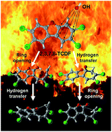
The ring-opening degradation mechanism of 2,3,7,8-tetrachlorinated dibenzofuran (2,3,7,8-TCDF) initiated by OH radicals is investigated using density functional theory. On the basis of the bimolecular reactions of 2,3,7,8-TCDF with OH radicals, the main study is focused on the subsequent unimolecular reactions, including ring-opening, hydrogen transfer and other chemical transformations. There are thirty-five reaction channels established according to the different reaction process. Ab initio calculations and reaction dynamic calculations are performed for all the reaction channels, and the calculated results are consistent with the available reported data, providing a detailed knowledge of the ring-opening degradation of 2,3,7,8-TCDF initiated by OH radicals. Generally, OH radicals can promote the ring-opening degradation of 2,3,7,8-TCDF, and the decomposition threshold temperature range of 2,3,7,8-TCDF is 500–850 K, which can serve as the technology parameter of the elimination of dioxins.

I. Introduction

Due to the acute toxicity, adverse biological effects and bioaccumulation,1,2 dioxins including polychlorinated dibenzo-p-dioxins (PCDDs) and polychlorinated dibenzofurans (PCDFs), the most notorious Persistent Organic Pollutant (POP), have drawn social and scientific attention and been subjected to plenty of scientific research. Among all the emission sources of dioxins, waste incineration is believed to be the major original source.3–7 Once emitted to the environment, dioxins can travel around from their emission sources by long-range atmospheric transport (LRAT), which has resulted in their global distribution.8,9 Dioxins can be removed through wet and dry deposition, photolysis reactions, and chemical reactions with several radicals in the atmosphere,10 and the residual dioxins may enter the food chain easily.2,11

Many pertinent studies on the formation and degradation of dioxins have been implemented, which could be a knowledge foundation for reducing the dioxin emissions, improving the treating technology and evaluating the environmental risk of dioxins. Relatively, the formation mechanism has been dissected well. Monocyclic aromatic compounds are regarded as the most important precursors for the formation of dioxins,12 such as 2-chlorophenol, 2,4-dichlorophenol, 2,4,5-trichlorophenol, 2,4,6-trichlorophenol13–17 and chlorobenzene.18,19 It enlightens us that the aromatic ring structure dioxin must be destroyed to prevent the regeneration of them. Several studies on the degradation of dioxins in the atmosphere have been reported, Lee and Choi20 carried out a theoretical study about the dibenzo-p-dioxins with OH radical. With the efforts of Altarawneh,21 the degradation mechanism of dibenzofuran (DF) initiated by OH addition was also studied. In recent years, Zhang, Sun and other coworkers22–24 have done a series of researches on the decomposition of dioxins initiated by OH radical in the presence of O2, NO2 and H2O. By the above literatures survey, OH radical seems to be the most meritorious active specie to react with dioxins, and is a kind of common radical formed under the combustion condition.25 However, the subsequent destruction reactions is not easy to be impelled under the atmospheric condition. So the thermal decomposition reaction of dioxins in waste incineration process is worth being investigated to the figure out the destruction mechanism of the cyclic aromatic framework of dioxins, by which we may find some feasible solutions to eliminate dioxins. The latest experiment studies on the oxidation and pyrolysis of dibenzo-p-dioxin and dibenzofuran were completed by Tritz26 and Summoogum,27 and some of decomposition products detected in the experiments are two-member ring compounds, it implies that the ring-opening process is involved in the thermal decomposition of dioxin. Taking this in consideration, it is will be a innovational and reasonable work to uncover the destruction mechanism of the dioxin cyclic aromatic framework.

In comparison with the PCDDs, the PCDFs show a higher chemical stability against thermal degradation.28 Additionally, PCDDs can be transformed into PCDFs under reducing condition.29 As a consequence, the amount of PCDFs found in the municipal waste incinerator is larger than that of PCDDs.30 Thus, in this paper, 2,3,7,8-tetrachlorinated dibenzofuran (2,3,7,8-TCDF) will be chosen as the sample to study the decomposition mechanism of dioxins. The envisaged degradation paths are started by the OH radical addition reactions of 2,3,7,8-TCDF. The OH radical addition breaks the conjugated electronic structure of 2,3,7,8-TCDF, the chemical stability is discounted relatively, which lays the foundation for the following unimolecular decomposition of 2,3,7,8-TCDF-OH adduct. The reaction channels of OH addition reactions and the subsequent unimolecular decomposition are illustrated in Fig. 1. There are thirty-five feasible reaction channels labeled as R1–R35, and the corresponding transition states, intermediates, and products are abbreviated to TS, IM, and P, which are attached with the serial numbers. Moreover, the reactant complexes formed at every reaction entrance are marked as RC, which will be mentioned in following section.


image file: c5ra13804c-f1.tif
Fig. 1 The possible reaction channels of 2,3,7,8-TCDF initiated by OH radical.

Ab initio calculation can provide accurate explanation and prediction for chemical reaction. In this study, density functional theory (DFT) is used to perform the electronic structure calculation, and the reaction kinetic data are also obtained on the basis of the calculation results.

II. Computational methods

The geometry structure of reactants, transition states, intermediates, and products were optimized using the B3LYP method35,36 with the 6-311+G(d,p) basis set, and the corresponding vibrational frequencies were calculated at the same level, which were scaled by a standard scaling factor37 of 0.9688 to remove systematic error. All transition states were verified to connect the designated reactants and products by performing an intrinsic reaction coordinate (IRC) analysis.38 To refine the energy information of the reaction potential energy surface (PES), higher level single point energy of all the stationary point on the PES were calculated by MPWB1K method39 with the 6-311+G(3df, 2p) basis set, and these energy values were all corrected by the zero point energy (ZPE). All the electronic structure calculations are performed by the Gaussian 09 program package40 on the platform of ScGrid.

With the reaction potential energy surface information and molecular properties provided by the preceding ab initio calculation, high-pressure limit rate constants of all the reaction channels were calculated over the temperature range of 300–2000 K. The reaction kinetics calculation was accomplished by the variable reaction coordinate transition state theory (VRC-TST)31,32 and Rice–Ramsperger–Kassel–Marcus (RRKM)33 theory implemented in the VARIFLEX code.41 Asymmetric Eckart tunneling corrections34 were included to correct the rate constants for the hydrogen transfer quantum effects at low temperature. For the tight transition states, the numbers of states were evaluated according to the rigid-rotor harmonic oscillator (RRHO) assumption.42 The rate constants were evaluated at the E/J resolved level,43 in order to achieve convergence in the integration over the energy range, an energy grain size of 130 cm−1 was used, these grain sizes provide numerically converged results for all temperatures studies with the energy E spanning range from 0 cm−1 to 104[thin space (1/6-em)]000 cm−1. The total angular momentum J covered the range from 0 to 900 in steps of 30 for the E/J-resolved calculation.

III. Results and discussion

For convenience, the serial numbers of the six different carbon sites on 2,3,7,8-TCDF distinguished by their chemical circumstance are labeled in Fig. 2.
image file: c5ra13804c-f2.tif
Fig. 2 Serial numbers of different carbon sites in 2,3,7,8-TCDF.

Stationary points

The geometry structure of 2,3,7,8-TCDF and OH radical optimized at B3LYP/6-311+G(d,p) level and the vibrational frequencies obtained at the same theoretical level are shown in Table 1. The main parameters and corresponding experimental reference data (in the parentheses) are labeled. By Table 1, the optimized geometry structure of 2,3,7,8-TCDF and OH are in good agreement with the reference data,44,45 and the wavenumbers of principal vibrational modes (in bold) are close to the experimental value (in the parentheses).44,46 It indicates that the computational precision of B3LYP/6-311+G(d,p) level is commendable. The geometry structure (in the form of Cartesian coordinates), rotational constants and vibrational frequencies of all the stationary points are provided in the ESI Tables S1 and S2.
Table 1 The equilibrium geometry structure and vibrational frequencies of 2,3,7,8-TCDF and OH radical obtained at B3LYP/6-31+G(d,p) level (experimental reference data are attached in the parentheses)
Species Frequencies (cm−1)
image file: c5ra13804c-u1.tif 3708(3737)
image file: c5ra13804c-u2.tif 46, 53, 103, 125, 145, 193, 204, 245, 253, 260, 260, 349, 383, 394, 400, 440, 443, 454, 486, 594, 638, 648, 650, 678(674), 709, 729, 732, 738, 814, 864, 871, 889(872), 892, 931(925), 939(944), 1053, 1109(1109), 1112, 1191(1109), 1216(1221), 1242, 1246, 1279(1282), 1316(1289), 1330, 1411, 1421(1402), 1469(1443), 1486, 1597, 1609, 1628(1600), 1665, 3201, 3202, 3216, 3216


Reaction mechanism and potential energy diagram

The whole chemical transformation process of 2,3,7,8-TCDF with OH radical can be divided into two part, the bimolecular association of 2,3,7,8-TCDF with OH radical and the unimolecular degradation of 2,3,7,8-TCDF-OH adduct. The OH radical addition can disrupt the conjugated electronic structure of 2,3,7,8-TCDF, consequently, the ring structure attacked by OH radical becomes more flexible, and the chemical stability declines, which lay the foundation for the following unimolecular reaction of 2,3,7,8-TCDF-OH adducts.

All the reaction paths are illustrated in the Schemes S1–S5, while the corresponding potential energy diagrams are present in the Fig. 3–7, in these figures, the energy value obtained at MPWB1K/6-311+G(3df,2p) level are listed under the specie names, and the corresponding energy values computed at B3LYP/6-311+G(d,p) level were attached in the parentheses. The energy sum of the reactants (2,3,7,8-TCDF and OH radical) was set to zero as the reference, and the energy difference between the stationary point and reactants was called as relative energy.


image file: c5ra13804c-f3.tif
Fig. 3 Potential energy diagram of the reactions of 2,3,7,8-TCDF initiated by the OH radical addition to carbon site 1 (unit: kcal mol−1).

image file: c5ra13804c-f4.tif
Fig. 4 Potential energy diagram of the reactions of 2,3,7,8-TCDF initiated by the OH radical addition to carbon site 2 (unit: kcal mol−1).

image file: c5ra13804c-f5.tif
Fig. 5 Potential energy diagram of the reactions of 2,3,7,8-TCDF initiated by the OH radical addition to carbon site 3 and 4 (unit: kcal mol−1).

image file: c5ra13804c-f6.tif
Fig. 6 Potential energy diagram of the reactions of 2,3,7,8-TCDF initiated by the OH radical addition to carbon site 5 (unit: kcal mol−1).

image file: c5ra13804c-f7.tif
Fig. 7 Potential energy diagram of the reactions of 2,3,7,8-TCDF initiated by the OH radical addition to carbon site 6 (unit: kcal mol−1).
The reactions initiated by OH radical addition to carbon site 1. The reaction paths started by OH radical addition to the carbon site 1 are described in the Scheme S1. There are eleven reaction channels marked as R1–R11. The 2,3,7,8-TCDF-OH adduct IM1 was formed through TS1. On the base of IM1, IM1-a and IM1-b were produced by the cleavage of C–C bond, IM1-c and IM1-d were formed through the hydrogen transfer from the OH radical to the adjacent carbon sites, and P1-e was generated by the cleavage of C–O bond. Then, IM1-a, IM1-b, IM1-c and IM1-d were further transformed into the third-step products by the hydrogen transfer and bond cleavage in the same way.

The potential energy diagram for the reactions initiated by the OH radical addition to carbon site 1 was presented in Fig. 3. As shown in the Fig. 3, the reactants complex (RC1) formed at the entrance of the reaction channels is actually in a state of pre-association. The energy barrier height of the bimolecular reaction process is much lower than that of the subsequent unimolecular reaction. The C–C bond opening reaction steps (IM1 → IM1-a, IM1 → IM1-b) need more energy consumption than hydrogen transfer reaction steps (IM1 → IM1-c, IM1 → IM1-d) and C–O bond cleavage (IM1 → P1-e). In the next step, IM1-a and IM1-b are transformed into the relatively stable products (P1-a-1, P1-a-2, P1-b-1, and P1-b-2) by intramolecular hydrogen transfers, while IM1-c and IM1-day are further processed by the cleavage of C–C bond or C–O bond containing the carbon site 1. Especially, there are four pairs of reaction channels R1-R5, R2-R8, R3-R6, R4-R9, and each pair share one common product. Comparing the ring openings resulting from the cleavage C–C bonds, the ring opening after the hydrogen transfer (IM1-c → P1-c-1, IM1-c → P1-c-2, IM1-d → P1-d-1, IM1-d → P1-d-2) are of lower energy barrier than the direct ring opening of IM1 (IM1 → IM1-a, IM1 → IM1-b), which indicates that the previous hydrogen transfer reaction can reduce the energy barrier height of the subsequent ring opening reaction. Among all the reaction channels shown in Fig. 3, channel R11 seems to be the major reaction path in perspective of potential energy barrier.

The reactions initiated by OH radical addition to carbon site 2. A brief description of the reaction process initiated by OH radical addition to carbon site 2 is presented in Scheme S2. There are seven reaction channels marked as R12–R18. The same reaction strategy is implemented at carbon site 2, the cleavage of C–C bond comes first, then hydrogen transfer follows, or the sequence is reversed. The reaction channel R14 is a special case, the third-step product P2-b-2 is formed by the combination of carbon site 3 and site 1, and the chlorine atom linked with carbon site 3 is delivered to carbon site 2 at the same time. For the sake of consummate research logic, it is must be informed that the other one reaction path branched from IM2-a is still of absence after the trial and error.

The potential energy diagram of the reactions of 2,3,7,8-TCDF initiated by the OH radical addition to carbon site 2 is shown in Fig. 4. The pre-associated reactants complex (RC2) is formed at the beginning of the reaction channels. By analysis, the C–C bond opening is more costly than hydrogen transfer. The ring opening after the hydrogen transfer (IM2-c → P2-c-1, IM2-c → P2-c-2, IM2-d → P2-d-1, IM2-d → P2-d-2) are of lower energy barrier than the direct ring opening of IM2 (IM2 → IM2-a, IM2 → IM2-b). Comparing R15 with R16, R17 with R18, we can found that the cleavage of the C–C bond containing the carbon atom which hydrogen transfers to consumes less energy relatively. Generally, channel R15 is believed to be the dominant reaction channel of the reaction system initiated by OH radical addition to carbon site 2.

The dechlorination reactions on the carbon site 3 and site 4. The dechlorination of 2,3,7,8-TCDF is illustrated in Scheme S3. The OH radical addition to 2,3,7,8-TCDF and the elimination of chlorine atom are a synergistic reaction. The energy fluctuation during the dechlorination process is exhibited in Fig. 5. The reactant complex RC3 and RC4 share a common geometry structure (see the ESI), and their relative energy is almost the same. The energy barrier height of reaction channel R19 is lower than that of R20, which is more competitive than R20.
The reactions initiated by OH radical addition to carbon site 5. As drawn in Scheme S4, the 2,3,7,8-TCDF-OH adduct IM5 is formed through the association of 2,3,7,8-TCDF with OH radical at carbon site 5. Then, IM5 is converted to IM5-a and IM5-b by the C–C bond cleavage. In the next step, P5-a-1 is produced through the hydrogen transfer, while P5-a-2 is generated by the combination of carbon site 6 and carbon site 4 forming a five-member ring, and the chlorine atom is delivered to carbon site 5 at the same time. P5-b-1 is also yielded by ring closure, i.e. the combination of carbon site 6 and carbon site 4, unlike the case of P5-a-2, the chlorine atom is reserved in this time. By the hydrogen transfer, IM5-c and IM5-d are formed, and then followed by the cleavage of bonds. In total, there are seven reaction channels marked as R21–R27.

The potential energy diagram of the reactions of 2,3,7,8-TCDF initiated by the OH radical addition to carbon site 5 is illustrated in Fig. 6. The energy barrier of C–C bond opening (IM5 → IM5-a, IM55 → IM5-b) is higher than that of hydrogen transfer (IM5 → IM5-c, IM55 → IM5-d). The C–C bond opening of IM5-c and IM5-d need less energy consumption than the C–C bond opening of IM5 (IM5 → IM5-a and IM5 → IM5-b), which implies that the C–C bond opening becomes much easier after the hydrogen transfer. Comparing reaction channel R24 with R25, R27 with R26, it can be found that the C–C bond containing the carbon atom which accepts hydrogen atom transferred from OH group is much easier to cleave. By comprehensive analysis, reaction channel R27 seems to be the most superior reaction path among the seven reaction channels started on carbon site 5.

The reactions initiated by OH radical addition to carbon site 6. The reactions of 2,3,7,8-TCDF initiated by the OH radical addition to carbon site 6 are illustrated in Scheme S5, and there are eight reaction channels marked as R28–R35. There are five reaction entrances for IM6 to enter the unimolecular transformation process. IM6-a and IM6-b and product P6-e are formed by the C–C bond cleavages of IM6, while IM6-c and IM6-d are generated by hydrogen transfers from OH group to the adjacent carbon. P6-a-1 is a unique product with a structure of single ring that formed by the cleavage of C–O bond in IM6-a. P6-b-1 is yielded through the intramolecular hydrogen transfer of IM6-b. The other products are produced by the cleavage of C–C bonds of the intermediates IM6-c and IM6-d.

The corresponding potential energy diagram is presented in Fig. 7. Reaction channel R28 is the most unpromising reaction path with the highest energy barrier, and P6-a-1 remain in a pretty high energy level. Particularly, the position of TS6-b is lower than that of TS6-c on the potential energy surface, the energy cost of hydrogen transfer from OH group to carbon site 1 (IM6 → IM6-c) is a little higher than that of the bond cleavage between carbon site 6 and site 5 (IM6 → IM6-b). Reaction channel R29 and R33 share a common product, and the structure and energy of P6-b-1 and P6-d-1 are all the same. Among all the reaction channels, R35 is the dominant reaction channel with the lowest energy barrier.

Rate constant

Bimolecular reactions of 2,3,7,8-TCDF with OH radical. As the energy information obtained by B3LYP and MPWB1K method are different, the corresponding rate constants at 298 K are both presented in Table 2, the rate constants of bimolecular reactions calculated by Sun and coworkers23 are also presented in Table 1 as the reference data. Comparing the rate constants obtained by B3LYP and MPWB1K with the reference data, we can find that the rate constants obtained by B3LYP method are much closer to the reference data, and the total rate constant at 298 K is 8.25 × 10⁻¹³ cm3 per molecule per s, which is almost equal to the sum of reference data and the total rate constant determined by QSAR method.10 Generally, the rate constants obtained at B3LYP level are more accurate and reliable than those obtained at MPWB1K level, thus the rate constants to be discussed in the following part of this paper are the rate constants at B3LYP level. To predict the rate constants at other temperature range, the three parameter expression formulas were also given in Table 1.
Table 2 The rate constants of bimolecular reaction of 2,3,7,8-TCDF with OH radical
Reactions k298 K Reference dataa Expression formula
B3LYP MPWB1K
a Ref. 23.b Ref. 10.
TCDF + OH → IM1 3.94 × 10⁻¹⁴ 2.30 × 10⁻¹⁶ 7.14 × 10⁻¹⁴ k1(T) = 8.86 × 10⁻²⁰T2.29 exp(−9.48/T)
TCDF + OH → IM2 1.04 × 10⁻¹³ 4.34 × 10⁻¹⁶ 1.90 × 10⁻¹³ k2(T) = 1.97 × 10⁻¹⁹T2.15 exp(278.82/T)
TCDF + OH → IM3 1.23 × 10⁻¹⁵ 8.51 × 10⁻¹⁸ 4.03 × 10⁻¹⁵ k3(T) = 4.36 × 10⁻²⁰T2.22 exp(−719.85/T)
TCDF + OH → IM4 1.31 × 10⁻¹⁵ 4.62 × 10⁻¹⁸ 1.08 × 10⁻¹⁵ k4(T) = 1.39 × 10⁻¹⁹T2.24 exp(−1077.80/T)
TCDF + OH → IM5 6.79 × 10⁻¹³ 2.41 × 10⁻¹⁴ 7.07 × 10⁻¹³ k5(T) = 3.62 × 10⁻¹⁹T2.15 exp(647.37/T)
TCDF + OH → IM6 3.80 × 10⁻¹⁶ 1.78 × 10⁻¹⁸ 9.75 × 10⁻¹⁶ k6(T) = 6.81 × 10⁻²⁰T2.24 exp(−1225.99/T)
Total rate constant 8.25 × 10⁻¹³ 2.48 × 10⁻¹⁴ 9.75 × 10⁻¹³  
Total rate constant determined by QSAR methodb: (0.40–1.00) × 10−12


To reveal the temperature dependence of the bimolecular reactions rate constants, all the rate constants were plotted against the temperature in Fig. 8. The rate constants are marked with serial number of the six carbon sites. As shown in Fig. 8, k5 is in the lead at the whole temperature range, it means that carbon site 5 is the most favorite reaction site for OH radical, which is in agreement with the previous study.23 Particularly, k3 and k4 are the rate constants of dechlorination reactions, which are relatively dismal at the whole temperature range. Totally, the dechlorination reaction is not as active as the OH radical addition reactions except for the OH radical addition to carbon site 6.


image file: c5ra13804c-f8.tif
Fig. 8 Rate constants of the bimolecular reaction of 2,3,7,8-TCDF with OH radical.
Unimolecular reaction of 2,3,7,8-TCDF-OH adduct. The subsequent unimolecular reactions of 2,3,7,8-TCDF-OH adducts (IM1, IM2, IM5, and IM6) make every main reaction path branched into a complex reaction tree. In order to compare the temperature dependence, the rate constants of initial bimolecular reactions and the subsequent unimolecular reactions are illustrated in the Fig. 9–12. The rate constants of unimolecular reactions were marked as kR1–R35.
image file: c5ra13804c-f9.tif
Fig. 9 Rate constants of the subsequent unimolecular reaction of IM1.

image file: c5ra13804c-f10.tif
Fig. 10 Rate constants of the subsequent unimolecular reaction of IM2.

image file: c5ra13804c-f11.tif
Fig. 11 Rate constants of the subsequent unimolecular reaction of IM5.

image file: c5ra13804c-f12.tif
Fig. 12 Rate constants of the subsequent unimolecular reaction of IM6.

The rate constants of the formation of IM1 and the subsequent unimolecular reaction of IM1 are plotted in Fig. 9. All the unimolecular reaction rate constants change dramatically with the temperature rising, and kR11 keeps dominating at the whole temperature. The bimolecular reaction rate constant k1 is presented as a near horizontal line crossing with curves of the unimolecular reaction rate constants. Two vertical lines were drawn from the two endpoint crossing points, and intersect at the axis of temperature, dividing the temperature range into three regions. When the temperature is below 350 K, unimolecular reactions are at the disadvantage, the consumption of IM1 cannot match the formation of IM1, resulting in the surplus of IM1; the middle temperature region between 350 K and 850 K is a transitionary part where the rate constants of the unimolecular reactions surpass that of bimolecular reaction gradually; in the high temperature region above 850 K, adduct IM1 can be consumed rapidly by the subsequent unimolecular reaction. Generally, the ring opening of 2,3,7,8-TCDF is completely achievable above 850 K.

The rate constants of the OH radical addition to the carbon site 2 and the subsequent unimolecular reaction of IM2 are illustrated in Fig. 10. Generally, the unimolecular reactions of IM2 are more sensitive to temperature than the association of 2,3,7,8-TCDF with OH radical. The rate constants are positively correlated with the temperature. Overall, kR15 dominates over the temperature range, which is consistent with the analysis of energy barrier. Similarly, the curve of rate constant k2 crosses with curves of the unimolecular reaction rate constants, then two vertical lines were stretched from the two endpoint crossing points to divide different temperature regions. When below 400 K, the bimolecular reaction is more active than unimolecular reaction; while the range of 400–500 K is the transitionary region, in which the unimolecular reactions start to reversal the situation, when the temperature is over 500 K, the unimolecular reactions show a overwhelming advantage, and the ring opening of 2,3,7,8-TCDF can be totally achieved when the temperature is over 500 K.

The rate constants of the OH radical addition to the carbon site 5 and the subsequent unimolecular reaction of IM5 are shown in Fig. 11. Obviously, the rate constants are positively correlated with the reaction temperature, and kR27 is in the dominant position at the whole temperature range. The unimolecular reactions of IM5 are more sensitive to temperature than the formation of IM5. Two vertical lines were drawn from the crossing points of the curves, by which the temperature axis was separated into three segments. When it is below 400 K, the unimolecular reactions of IM5 are the rate-determining step of the global reaction, while the unimolecular reactions start to surmount at the temperature range of 400–600 K, once the temperature exceeds 600 K, unimolecular reactions become faster and faster, the OH radical addition becomes the rate-determining step of global reaction. Overall, the ring opening of 2,3,7,8-TCDF can be totally achieved over 600 K in this case.

The rate constants of the OH radical addition to the carbon site 6 and the subsequent unimolecular reaction of IM6 are plotted in Fig. 12. Apparently, kR35 is in the lead at the whole temperature range, while kR28 lags behind the other reaction channels at the whole temperature range. Draw two vertical lines from the two endpoint crossing points to intersect with the axis of temperature dividing the whole temperature into three regions. When below 300 K, the unimolecular reactions are immature, which are the rate-determining steps of the global reaction. After a short temperature rise, the rate constants of unimolecular reactions increase extremely; when temperature is over 500 K, the unimolecular reactions is relative prosperous, and the global reaction rate constant is determined by the formation of IM6. In conclusion, the ring-opening destruction of IM6 can be achieved when the temperature is over 500 K.

According to the discussion above, the unimolecular decomposition can be motivated at the threshold temperature range of 500–850 K. In 1986, Vogg H. and Stieglitz L.28 reported that the decomposition of dioxins can occur at medium temperatures about 600 °C (873.15 K), and the same conclusion was mentioned in the paper published by Lundin and Marklund47 in 2005. Apparently, the theoretic research results in this paper are very close to those of the related experiment study, which are relatively reliable.

IV. Conclusion

Generally, the OH radical play a very important role in the ring-opening degradation of 2,3,7,8-TCDF. The OH radical addition reaction and hydrogen transfer can break the conjugated electronic structure of 2,3,7,8-TCDF, which can efficiently promote the destruction like a kind of catalyst. In addition, the reaction temperature must be kept above 500–850 K to guarantee the destruction of 2,3,7,8-TCDF framework, and the threshold temperature range of 500–850 K can serve as the technology parameter of the elimination of dioxins.

Actually, more unimolecular decompositions can occur further to break the framework of 2,3,7,8-TCDF into small molecules. We hope that the reactions process investigated in this paper can provide a reference basis for the study of complete destruction of dioxins, and the same research procedure can also be applied in the study on the degradation of other dioxin congeners.

Acknowledgements

The authors declare no competing financial interest. This work was supported financially by the the National Basic Research Program of China (2012CB723308), the National Natural Science Foundation of China (51337002 and 50977019), the Doctoral Foundation by the Ministry of Education of China (20112303110005), the Science Foundation for Distinguished Young Scholar of Heilongjiang Province (JC201206).We thank the Computer Network Information Center of Chinese Academy of Sciences for providing computational service on the ScGrid.

References

  1. M. van den Berg, L. Birnbaum, A. T. Bosveld, B. Brunström, P. Cook, M. Feeley, J. P. Giesy, A. Hanberg, R. Hasegawa, S. W. Kennedy, T. Kubiak, J. C. Larsen, F. X. van Leeuwen, A. K. Liem, C. Nolt, R. E. Peterson, L. Poellinger, S. Safe, D. Schrenk, D. Tillitt, M. Tysklind, M. Younes, F. Waern and T. Zacharewski, Environ. Health Perspect., 1998, 106(12), 775 CrossRef CAS.
  2. D. Broman, C. Rolff, C. Näf, Y. Zebühr, B. Fry and J. Hobbie, Environ. Toxicol. Chem., 1992, 11(3), 331 CrossRef CAS.
  3. P. S. Kulkarni, J. G. Crespo and C. A. M. Afonso, Environ. Int., 2008, 34(1), 139 CrossRef CAS PubMed.
  4. J. I. Baker and R. A. Hites, Environ. Sci. Technol., 2000, 34(14), 2879 CrossRef CAS.
  5. A. Buekens, L. Stieglitz, K. Hell, H. Huang and P. Segers, Chemosphere, 2001, 42(5–7), 729 CrossRef CAS.
  6. A. Yasuhara, T. Katami, T. Okuda, N. Ohno and T. Shibamoto, Environ. Sci. Technol., 2001, 35(7), 1373 CrossRef CAS.
  7. J. M. Czuczwa and R. A. Hites, Environ. Sci. Technol., 1984, 18(6), 444 CrossRef CAS PubMed.
  8. D. M. Wagrowski and R. A. Hites, Environ. Sci. Technol., 2000, 34(14), 2952 CrossRef CAS.
  9. R. Lohmann, W. A. Ockenden, J. Shears and K. C. Jones, Environ. Sci. Technol., 2001, 35(20), 4046 CrossRef CAS.
  10. R. Atkinson, in Issues in environmental science and technology, ed. R. E. Hester and R. M. Harrison, The Royal Society of Chemistry, Cambridge, U.K, 1996 Search PubMed.
  11. A. Bernard, F. Broeckaert, G. De Poorter, A. De Cock, C. Hermans, C. Saegerman and G. Houins, Environ. Res., 2002, 88(1), 1 CrossRef CAS PubMed.
  12. J. A. Mulholland, U. Akki, Y. Yang and J. Y. Ryu, Chemosphere, 2001, 42(5–7), 719 CrossRef CAS.
  13. M. Altarawneh, B. Z. Dlugogorski, E. M. Kennedy and J. C. Mackie, J. Phys. Chem. A, 2007, 111(13), 2563 CrossRef CAS PubMed.
  14. Q. Zhang, J. Huang and G. Yu, Environ. Pollut., 2008, 151(1), 39 CrossRef CAS PubMed.
  15. Q. Zhang, S. Li, X. Qu, X. Shi and W. Wang, Environ. Sci. Technol., 2008, 42(19), 7301 CrossRef CAS.
  16. X. Qu, H. Wang, Q. Zhang, X. Shi, F. Xu and W. Wang, Environ. Sci. Technol., 2009, 43(11), 4068 CrossRef CAS.
  17. Q. Zhang, W. Yu, R. Zhang, Q. Zhou, R. Gao and W. Wang, Environ. Sci. Technol., 2010, 44(9), 3395 CrossRef CAS PubMed.
  18. P. Y. Liu, M. H. Zheng, B. Zhang and X. B. Xu, Chemosphere, 2001, 43(4–7), 783 CrossRef CAS.
  19. M. Altarawneh, B. Z. Dlugogorski, E. M. Kennedy and J. C. Mackie, in Seventh Asia–Oceania symposium on fire science and technology, Hong Kong, 2007 Search PubMed.
  20. J. E. Lee, W. Choi, B. J. Mhin and K. Balasubramanian, J. Phys. Chem. A, 2004, 108(4), 607 CrossRef CAS.
  21. M. Altarawneh, E. M. Kennedy, B. Z. Dlugogorski and J. C. Mackie, J. Phys. Chem. A, 2008, 112(30), 6960 CrossRef CAS PubMed.
  22. C. Zhang, T. Sun and X. Sun, Environ. Sci. Technol., 2011, 45(11), 4756 CrossRef CAS PubMed.
  23. X. Sun, C. Zhang, Y. Zhao, J. Bai, Q. Zhang and W. Wang, Environ. Sci. Technol., 2012, 46(15), 8148 CrossRef CAS PubMed.
  24. C. Zhang, Y. Zhao, J. Bai, C. Gong and X. Sun, Sci. Total Environ., 2012, 435, 53 CrossRef PubMed.
  25. T. Aizawa, Appl. Opt., 2001, 40(27), 4894 CrossRef CAS.
  26. A. Tritz, I. Ziegler-Devin, C. Perrin and P. M. Marquaire, J. Environ. Chem. Eng., 2014, 2(1), 143 CrossRef CAS PubMed.
  27. S. L. Summoogum, M. Altarawneh, J. C. Mackie, E. M. Kennedy and B. Z. Dlugogorski, Combust. Flame, 2012, 159(10), 3056 CrossRef CAS PubMed.
  28. H. Vogg and L. Stieglitz, Chemosphere, 1986, 15(9), 1373 CrossRef CAS.
  29. M. Altarawneh, B. Z. Dlugogorski, E. M. Kennedy and J. C. Mackie, J. Phys. Chem. A, 2007, 111(30), 7133 CrossRef CAS PubMed.
  30. G. Schwarz, L. Stieglitz and W. Roth, Organohalogen Compd., 1990, 3, 169 CAS.
  31. S. H. Robertson, A. F. Wagner and D. M. Wardlaw, Faraday Discuss., 1995, 102, 65 RSC.
  32. S. H. Robertson, A. F. Wagner and D. M. Wardlaw, J. Chem. Phys., 1995, 103(8), 2917 CrossRef CAS PubMed.
  33. D. M. Wardlaw and R. A. Marcus, Chem. Phys. Lett., 1984, 110(3), 230 CrossRef CAS.
  34. C. Eckart, Phys. Rev., 1930, 35(11), 1303 CrossRef CAS.
  35. A. D. Becke, J. Chem. Phys., 1993, 98(7), 5648 CrossRef CAS PubMed.
  36. C. Lee, W. Yang and R. G. Parr, Phys. Rev. B: Condens. Matter Mater. Phys., 1988, 37(2), 785 CrossRef CAS.
  37. J. P. Merrick, D. Moran and L. Radom, J. Phys. Chem. A, 2007, 111(45), 11683 CrossRef CAS PubMed.
  38. K. Fukui, Acc. Chem. Res., 1981, 14(12), 363 CrossRef CAS.
  39. Y. Zhao and D. G. Truhlar, J. Phys. Chem. A, 2004, 108(33), 6908 CrossRef CAS.
  40. M. J. Frisch, G. W. Trucks, H. B. Schlegel, G. E. Scuseria, M. A. Robb, J. R. Cheeseman, G. Scalmani, V. Barone, B. Mennucci, G. A. Petersson, H. Nakatsuji, M. Caricato, X. Li, H. P. Hratchian, A. F. Izmaylov, J. Bloino, G. Zheng, J. L. Sonnenberg, M. Hada, M. Ehara, K. Toyota, R. Fukuda, J. Hasegawa, M. Ishida, T. Nakajima, Y. Honda, O. Kitao, H. Nakai, T. Vreven, J. A. Montgomery, Jr, J. E. Peralta, F. Ogliaro, M. Bearpark, J. J. Heyd, E. Brothers, K. N. Kudin, V. N. Staroverov, R. Kobayashi, J. Normand, K. Raghavachari, A. Rendell, J. C. Burant, S. S. Iyengar, J. Tomasi, M. Cossi, N. Rega, J. M. Millam, M. Klene, J. E. Knox, J. B. Cross, V. Bakken, C. Adamo, J. Jaramillo, R. Gomperts, R. E. Stratmann, O. Yazyev, A. J. Austin, R. Cammi, C. Pomelli, J. W. Ochterski, R. L. Martin, K. Morokuma, V. G. Zakrzewski, G. A. Voth, P. Salvador, J. J. Dannenberg, S. Dapprich, A. D. Daniels, O. Farkas, J. B. Foresman, J. V. Ortiz, J. Cioslowski and D. J. Fox, Gaussian 09, Gaussian, Wallingford CT, 2009 Search PubMed.
  41. S. J. Klippenstein, A. F. Wagner, S. H. Robertson, R. Dunbar and D. M. Wardlaw, Variflex Software Version 1.0, Argonne National Laboratory, Argonne IL, 1999 Search PubMed.
  42. S. E. Stein and B. S. Rabinovitch, J. Chem. Phys., 1973, 58(6), 2438 CrossRef CAS PubMed.
  43. S. J. Klippenstein, J. Phys. Chem., 1994, 98(44), 11459 CrossRef CAS.
  44. K. P. Huber and G. Herzberg, in Constants of Diatomic Molecules; Van Nostrand Reinhold Co., New York, 1979 Search PubMed.
  45. C. R. Hubbard, A. D. Mighell and I. H. Pomerantz, Acta Crystallogr., Sect. B: Struct. Crystallogr. Cryst. Chem., 1978, 34(7), 2381–2384 CrossRef.
  46. C. J. Wurrey, B. J. Fairless and H. E. Kimball, Appl. Spectrosc., 1989, 43(8), 1317 CrossRef CAS.
  47. L. Lundin and S. Marklund, Environ. Sci. Technol., 2005, 39(10), 3872 CrossRef CAS.

Footnote

Electronic supplementary information (ESI) available: Tables S1 and S2 and Schemes S1–S5. See DOI: 10.1039/c5ra13804c

This journal is © The Royal Society of Chemistry 2015
Click here to see how this site uses Cookies. View our privacy policy here.