DOI:
10.1039/C5RA13483H
(Paper)
RSC Adv., 2015,
5, 83056-83064
A highly reversible Li–O2 battery utilizing a mixed electrolyte and a cathode incorporating Co3O4†
Received
9th July 2015
, Accepted 18th September 2015
First published on 18th September 2015
Abstract
The present work mainly focuses on aprotic electrolytes in order to improve the performance of Li–O2 cells. The single-solvent electrolytes are based on tetraethylene glycol dimethyl ether (TEGDME), dimethyl sulfoxide (DMSO) and ionic liquid 1-ethyl-3-methylimidazolium bis(trifluoromethylsulfonyl)imide (EMITFSI), respectively. Compared to TEGDME and EMITFSI electrolytes, the DMSO electrolyte leads to higher reversible Li–O2 cells, even though decomposition of DMSO is observed. In this work, novel blended TEGDME (20 wt%)–DMSO (80 wt%), EMITFSI (20 wt%)–TEGDME (80 wt%) and EMITFSI (20 wt%)–DMSO (80 wt%) based electrolytes are first proposed and investigated in the assembled Li–O2 cells. Incorporating with a Co3O4 catalysed cathode, the EMITFSI–DMSO electrolyte results in an optimized Li–O2 battery, showing a lower voltage gap and a higher reversibility. In such a system, 80% of the recharge occurs at a potential underneath 4.0 V vs. Li+/Li. The low recharge voltage can suppress the decomposition of DMSO and favour a longer cycle life. More than 65 consecutive cycles are achieved at a current density of 0.1 mA cm−2 with a cut-off capacity of 835 mA h gelectrode−1. The improved electrochemical performance is attributed to the enhanced ionic conductivity of the mixed electrolyte. In addition, the EMITFSI–DMSO electrolyte is considered more stable, since the ionic liquid could alleviate the decomposition of DMSO provoked by the intermediate superoxides.
Introduction
The first example of a rechargeable Li–O2 battery was proposed by Abraham and Jiang in 1996 and it comprised a Li+-conductive PAN-based polymer electrolyte sandwiched between a Li metal foil anode and a carbon composite cathode.1 The cell delivered a discharge capacity of 1410 mA h gcarbon−1 and high columbic efficiency for at least 3 cycles. Such limited cycle-ability hindered the research interest towards Li–O2 batteries in the following ten years. With the increasing environmental problems, rising oil prices and economic crisis, Li–O2 batteries have regained worldwide interest since they can potentially provide 2–3 times higher practical specific energy densities than the current Li-ion batteries, enabling the driving range of electric vehicles to be comparable to that of gasoline vehicles. The work so far focused the attention on various aspects of Li–O2 technology, including mainly porous and nanostructured electrodes, bi-functional catalysts as well as liquid and solid electrolytes.2,3 Nevertheless, the Li–O2 technology is still in its early stage and the reversibility of the system is far from being adequate, with a life-span ranging from tens to hundreds of cycles, depending on both of the cathode materials and the electrolyte formulations. Non-aqueous electrolytes represent one of the main unsolved issues in the aprotic Li–O2 cells, due to their poor stability against reactive reduced oxygen species and questionable compatibility related to the electrolyte–anode interface. At the early stage, organic carbonate electrolytes were extensively used due to their great success in Li-ion batteries.4–7 Although the cell was demonstrated to be rechargeable with the organic carbonate electrolytes, quick decomposition of such electrolytes was observed. The detected discharge products were mainly irreversible Li2CO3 and LiRCO3 byproducts, which were responsible for the fast capacity decay.8–10 As organic carbonates are unsuitable solvents for Li–O2 batteries, ether-based electrolytes (tri- and tetra-glymes) attracted significant attention due to their affinity with Li metal, wide electrochemical stability window and low volatility. The reversible formation of Li2O2 was reported in the cells using TEGDME-based electrolytes.11 Scrosati and co-workers demonstrated the high feasibility of such electrolytes, as the cell assured over 100 stable discharge–charge cycles with a capacity of 1000 mA h g−1.12 In contrast, some works reported that the ether-based electrolytes were unable to maintain the required reversible formation/decomposition of Li2O2 upon cycling.13 Alternatively, Xu and co-workers proposed DMSO based electrolyte for Li–O2 cells and superior rate capability combined with low voltage gap were demonstrated.14 Bruce and co-workers further reported the good performance of a Li–O2 battery with DMSO electrolyte coupled with nanoporous gold cathode.15 Highly pure Li2O2 was formed during discharge and decomposed during charge, which allowed the cell to sustain 100 cycles with 95% capacity retention. Even though DMSO is considered a practical solvent for rechargeable Li–O2 batteries, the formation of LiOH was detected on pure carbon black cathode and super P cathode incorporating α-MnO2.15,16 Alternatively, room temperature ionic liquids (RTILs) were proposed as suitable electrolytes for Li–O2 cells due to their high conductivity, non-volatility and non-flammability. Kuboki and co-workers examined some RTILs with various hydrophobicity for Li–air systems and considered EMITFSI a suitable electrolyte component due to its capability to prevent the electrolyte vaporization and anode hydrolysis.17 The reversible formations of Li2O and Li2O2 were observed on gold electrodes in EMITFSI by cyclic voltammetry.18 Mizuno and co-workers investigated an electrolyte based on ionic liquid N-methyl-N-propylpiperidiniumbis(trifluoromethanesulfonyl) amide (PP13TFSA) in Li–O2 batteries.19 The PP13TFSA electrolyte resulted in a quite low charge voltage of around 3.3 V due to its high stability against the superoxide radical. A blended electrolyte of an ionic liquid N-methyl-N-butylpyrrolidinium bis(trifluoromethanesulfonyl)imide (PYR14TFSI) and TEGDME was also explored.20 The charge over-potential significantly decreased in the blended electrolyte. However, the cells demonstrated quite low current rates and poor durability. Kim and co-workers reported a mixed electrolyte of an organic carbonate (propylene carbonate, PC) and an ionic liquid N-propyl-N-methylpyrrolidinium bis(trifluoromethanesulfonyl)imide (PYR13TFSI) for Li–O2 batteries.21 The blended electrolyte improved the cycle life of the Li–O2 cells but resulted in a voltage gap of more than 1.5 V. Recently, a mixture electrolyte based on DMSO and an ionic liquid PYR14TFSI was studied by Khan and co-worker.22 Excellent reversibility of oxygen reduction reaction (ORR) and oxygen evolution reaction (OER) was observed by cyclic voltammetry in the electrolyte. Nonetheless, the performance of the DMSO–IL electrolyte in a practical Li–O2 cell system was not reported.
Clearly, the electrolyte plays a tremendous role on the performance of Li–O2 batteries, affecting the discharge capacity, the voltage gap, the recharge ability and so on. The continuous exploration of practical electrolytes is vital for developing high-performance Li–O2 batteries. The paper addresses this topic and considers the role of different solvents, namely DMSO, TEGDME and EMITFSI, on the cell electrochemical performance when coupled with pure carbon cathodes and carbon incorporating home-made Co3O4 cathodes. EMITFSI has been chosen as the candidate due to its relatively low viscosity, super hydrophobicity and outstanding ionic conductivity at room temperature, compared with the other ionic liquids. The working electrochemical stability window of the EMITFSI is not large, which was between 1.5 V to 4.8 V vs. Li/Li+.23 However, the Li–O2 cells operate in a voltage range of 2.25–4.30 V vs. Li/Li+, which is considered safe for the EMITFSI electrolyte. In this work, DMSO electrolyte resulted in impressive long-life batteries with both types of cathodes, compared to the other two candidates. In previous work, we reported the performance and cycling ability of Li–O2 cells, based on TEGDME electrolyte and mesoporous Co3O4 catalysed electrodes.24 The present work further confirms the positive effect of Co3O4 cathode on the cycle life of Li–O2 in DMSO electrolyte. Our ultimate goal is to propose some novel blended electrolytes, namely DMSO–TEGDME, TEGDME–EMITFSI and DMSO–EMITFSI, which enable the Li–O2 cells to work with a lower voltage gap and a longer cycle life.
Experimental
Unless and until mentioned separately, the chemicals used in the study are analytical grade and used as received from Sigma Aldrich. The EMITFSI is battery grade and used as received from Solvionic.
Structural-morphological characterization
The X-ray diffractions analysis were carried out using a Philips X'pert MPD powder diffractometer, equipped with Cu Kα radiation. The morphology of the samples was examined using field-emission scanning electron microscopy (FESEM, JEOL-JSM-6700F).
Preparation of mesoporous Co3O4
The Co3O4 catalyst was synthesized using a template-free method, as described in our previous work.24 Briefly, 1.8 g of Co(NO3)2 and 0.4 g of NH4NO3 were dissolved in 35 g of H2O and 14 g of ammonia solution (30 wt%). The homogeneous solution was then magnetically stirred for 20 min in air. During the stirring, the initial pink colour gradually turned into black, which indicates that part of the Co(II) oxidized into Co(III). The solution was then covered by a glass dish and kept in a preheated oven at 90 °C for 12 h. The as-prepared sample was filtered and then thoroughly washed with H2O and acetone. The obtained powder was vacuum dried at 50 °C and then calcined in air at 250 °C for 2 h to get the final sample.
Preparation of cathodes
The O2 electrode was prepared as a coating layer over carbon paper gas-diffusion layer (GDL, SIGRACET GDL-24BC, SGL Technologies), which ensures facile transport of O2 gas phase to the electrode surface.25 To prepare pure carbon cathodes, acetylene carbon black (Shawinigan Black AB50, referred to Csw) and poly-(vinylidenefluoride) (referred to PVdF) binder, in the weight ratio of 85![[thin space (1/6-em)]](https://www.rsc.org/images/entities/char_2009.gif) :15, were well mixed utilizing a mixer mill (Retsch, MM 400). N-Methyl-2-pyrrolidone (NMP) solvent was then added to the solid mixture in order to obtain a uniform slurry. The slurry was coated on top of the microporous layer of the GDL using doctor blade technique. This coating was dried at 55 °C overnight to evaporate the NMP solvent. The as-prepared cathodes were further dried in vacuum at 120 °C for 6 h before testing in Li–O2 cells. Catalysed electrodes with home-made Co3O4, Csw and PVDF (weight ratio of 30:55:15) were prepared with the same procedure. During the preparation, the slurries with different compositions were tuned with a similar viscosity using NMP solvent. The thickness of the deposited slurry was set at 300 μm. Thus, no significant difference in the thickness of the coating layers was observed for various compositions. The coating layer had a total loading of 1.0 mg cm−2 for Csw carbon electrodes and 1.2 mg cm−2 for electrodes incorporating Co3O4.
:15, were well mixed utilizing a mixer mill (Retsch, MM 400). N-Methyl-2-pyrrolidone (NMP) solvent was then added to the solid mixture in order to obtain a uniform slurry. The slurry was coated on top of the microporous layer of the GDL using doctor blade technique. This coating was dried at 55 °C overnight to evaporate the NMP solvent. The as-prepared cathodes were further dried in vacuum at 120 °C for 6 h before testing in Li–O2 cells. Catalysed electrodes with home-made Co3O4, Csw and PVDF (weight ratio of 30:55:15) were prepared with the same procedure. During the preparation, the slurries with different compositions were tuned with a similar viscosity using NMP solvent. The thickness of the deposited slurry was set at 300 μm. Thus, no significant difference in the thickness of the coating layers was observed for various compositions. The coating layer had a total loading of 1.0 mg cm−2 for Csw carbon electrodes and 1.2 mg cm−2 for electrodes incorporating Co3O4.
Electrochemical tests
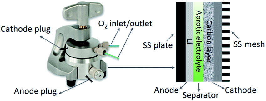
A lithium disc (18 × 0.2 mm, Chemetall s.r.l.) was used as the anode. A glass fibre (18 × 0.65 mm, ECC1-01-0012-A/L) saturated in the electrolyte was used as the separator. All the electrolyte formulations comprised 5 wt% of lithium perchlorate (LiClO4) salt, which was about 0.5 M LiClO4. LiClO4 was selected as salt due to its superior stability during the discharge process.26 Lithium bis(trifluoromethanesulfonyl)imide (LiTFSI) is also considered a stable salt for Li–O2 cells. However, researches revealed that TFSI− anions might decompose on the Li surface by a strong nucleophilic reaction with LiO2˙ in the DMSO based electrolyte, which increases the degradation of anode.27 The Li–O2 cell was then assembled in an Ar-filled dry glove box (Mbraun Labstar) using an ECC-Air electrochemical cell (EL-Cell, GmbH) configuration with openings allowing oxygen to enter and exit through the cathode side. Fig. 1 illustrates the configuration and internal assembly of a Li–O2 cell used in the present work. The cathode comprises a GDL substrate and a carbon layer or a catalysed carbon layer, on which the electrochemical reactions occur. The geometric area of the cells was 2.54 cm2.
 |
| | Fig. 1 Illustration of the configuration and internal assembly of a Li–O2 cell. | |
In order to evaluate the discharge capacity, the cells were galvanostatically discharged by an Arbin BT-2000 battery tester at room temperature, from the open circuit voltage (OCV) to 2.15 V vs. Li+/Li. Hereafter, all the voltages mentioned in this article are versus to Li+/Li. To investigate the cycle-ability of the cells, galvanostatic time-controlled charge and discharge steps were carried out. During the cycling test, the discharge step terminated when the discharge voltage arrived at 2.25 V or the discharge time reached 10 h, and the recharge step ended when the recharge voltage went up to 4.30 V or the recharge time reached 10 h. Throughout all the electrochemical tests, the cells were continuously purged with dry O2 at a gas flow rate of 3.0 mL min−1. Prior to each test, the Li–O2 cell rested 6 h at OCV under oxygen flow. The ionic conductivity of the electrolytes was determined by electrochemical impedance spectroscopy (EIS) analysis of cells formed with electrolyte-saturated separator sandwiched by two stainless-steel electrodes, using a PARSTAT-2273 potentiostat instrument.23
Results and discussion
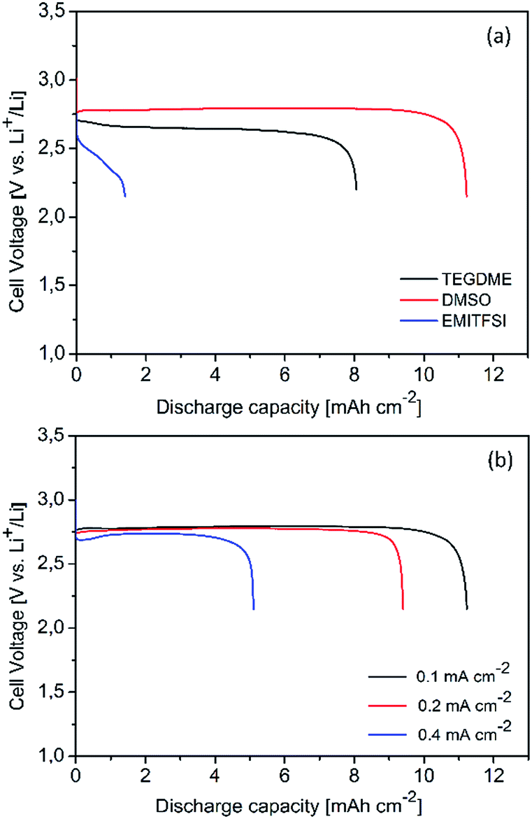
In order to analyze the effect of the electrolytes on the discharge capacity, a first full discharge of carbon (Csw) cathodes was carried out at 0.1 mA cm−2. As shown in Fig. 2a, the electrolytes significantly influenced the discharge performance of the Li–O2 cells. The discharge performance is mainly related to the combined properties of viscosity, ionic conductivity, oxygen solubility, diffusion coefficient, and other characteristics (e.g., the wettability on the cathodes) of each electrolyte. The cell with DMSO electrolyte displayed a lower discharge overpotential, distinguishing the advantage of DMSO electrolyte over TEGDME and EMITFSI electrolytes. As presented in Table 1, the DMSO solvent has a high O2 diffusion coefficient and low viscosity, which enhance the O2 transfer in the electrolyte-flooded cathode. The ionic conductivity of the electrolytes was studied by EIS analysis.29 The ionic conductivity σ, in S cm−1, can be calculated from
 |
| | Fig. 2 (a) Full discharge curves of carbon cathodes using various electrolytes at 0.1 mA cm−2; (b) full discharge curves of carbon cathodes using DMSO electrolyte at various current densities. | |
Table 1 Properties of investigated solvents and electrolytes
| Solvent |
Boiling point (°C) |
Viscosity (cP) |
O2 solubility (mM cm−1) |
O2 diffusion coefficient (×10−5 cm2 s−1) |
Conductivitya (mS cm−1) |
| Ionic conductivity of electrolyte with 0.5 M LiClO4, which was determined by EIS analysis. |
| TEGDME |
275 |
4.0 |
4.4 (ref. 28) |
0.22 (ref. 28) |
0.7 |
| DMSO |
189 |
1.9 |
1.8 (ref. 22 and 28) |
1.80 (ref. 22 and 28) |
6.1 |
| EMITFSI |
— |
28.0 |
3.9 (ref. 18) |
0.73 (ref. 18) |
4.4 |
where Rb: the resistance of the electrolyte (Ω), obtained from the high frequency intercept of the fitted impedance spectrum on the Zre axis. L: the thickness of the separator, which is 0.065 cm. A: the active area of the separator, which is the geographical area of the EL-Cell 2.54 cm2.
The Rb can be directly read from Fig. S1 (ESI†), which is 37.1, 4.2, 5.7 Ω for TEGDME, DMSO and EMITFSI electrolyte, respectively. The calculated ionic conductivity is 0.7, 6.1, 4.4 mS cm−1 for TEGDME, DMSO and EMITFSI electrolyte, respectively. The high ionic conductivity of DMSO electrolyte further favoured the discharge process at high current rates, as shown in Fig. 2b. The discharge capacity and the cell voltage were not compromised with increasing the current density from 0.1 mA cm−2 to 0.2 mA cm−2, indicating the possibility to enhance the power density of the cells using DMSO electrolyte. Conversely, a decrease in the discharge performance with increasing the current density was observed in TEGDME electrolyte, which could result from the mass transfer limitation (O2, Li+ or electrons) at the active sites of cathodes.30
It is noticed that the ionic liquid EMITFSI possesses such a high viscosity that significantly hinders the mass transport. As presented in Fig. 2a, the cell with EMITFSI electrolyte experienced very poor discharge capacity and high overpotential, which are likely due to the concentration overpotential rather than insoluble discharge products choking the porous cathodes. Furthermore, a discharge rate of 0.1 mA cm−1 is considered too high for cells discharging in such ionic liquid electrolytes.31 Post-mortem analyses such as XRD and FESEM were carried out on the fully discharged electrodes after cell disassembly. As shown in XRD patterns (Fig. 3a), Li2O2 was the dominant discharge product using TEGDME electrolyte. On the discharged cathode in DMSO, Li2O2 as well as a significant amount of LiOH were detected. Such discharged products are in the form of crystalline phases similar to those reported in literature.27 Behaving as a Lewis base, the use of DMSO solvent in Li+ containing electrolytes can stabilize the soluble superoxide intermediates, which contributes to the higher discharge voltage. However, such process is usually accompanied by side reactions that result in the formation of additional discharge by-products aside from Li2O2.16 Possible reactions provoked by O2− could be depicted in eqn (1) and (2):16
| | |
CH3SOCH3 + O2− → CH3SOCH2− + O2H
| (1) |
| | |
2O2H + 2Li+ + 2e− → 2LiOH + O2
| (2) |
 |
| | Fig. 3 (a) X-ray diffraction patterns of carbon electrodes after full discharge using various electrolytes at 0.1 mA cm−2 (ICDD database: Li2O2, 00-009-0355; LiOH, 00-004-0708); FESEM images of carbon cathodes after full discharge: (b) using TEGDME electrolyte; (c) using DMSO electrolyte; (d) using EMITFSI electrolyte. | |
The cathode discharged in the EMITFSI electrolyte displays a XRD pattern similar to the pristine cathode (Fig. S2a (ESI†)). No peaks attributed to Li2O2 were observed on, probably due to an undetectable amount of discharge products or to the formation of amorphous phases.32 FESEM images of surface morphologies of the O2 electrodes discharged in TEGDME, DMSO and EMITFSI are shown in Fig. 3b–d, respectively. Uniform toroids were observed on the electrode discharged in the TEGDME, typical of Li2O2 nanocrystallites aggregation. DMSO promoted the formation of flake-like agglomerations apart from toroids on the cathode surface. Such agglomerates are considered to be mixed LiOH and Li2O2 nanocrystallites. The possible mechanism of the formation of LiOH has been described in eqn (1) and (2). The discharged cathode in the EMITFSI electrolyte matched the profile of a pristine Csw carbon cathode (Fig. S2b (ESI†)), indicating that no significant amount of products accumulated during the discharge.
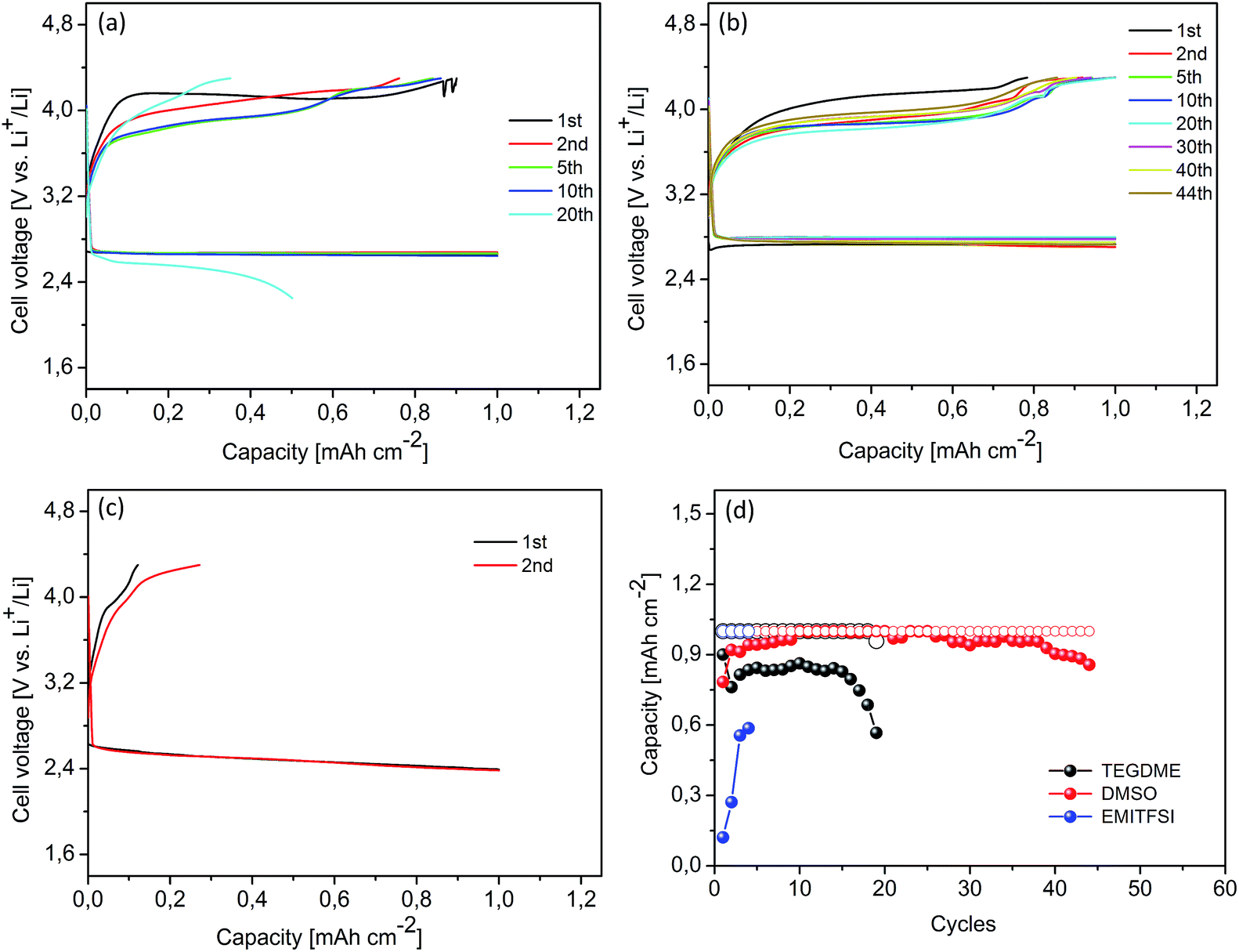
Cyclic voltammetry in DMSO electrolyte revealed the full reversal oxygen reduction/evolution reactions throughout multiple reactions involving four electrons, which makes DMSO a particularly attractive solvent for rechargeable Li–O2 batteries.16,28 Even though the decomposition of DMSO was observed during the discharge process, the results present herein show evidence that DMSO electrolyte sustains the cell reversibility better than the TEGDME and EMITFSI electrolytes operating at the same experimental conditions. As presented in Fig. 4, three Li–O2 cells with Csw cathodes were galvanostatically cycled in the different electrolytes from 2.25 V to 4.30 V at a current density of 0.1 mA cm−2 with a cut-off capacity of 1.0 mA h cm−2. The cell with the DMSO electrolyte (in Fig. 4b) presented a voltage gap of 1.1 V at the second cycle, a value slightly lower than 1.3 V observed with TEGDME (in Fig. 4a). Fig. 4c illustrates the discharge/charge profiles of a cell using EMITFSI electrolyte. The cell displayed a large voltage gap and weak recharge ability, due to the high mass transfer resistance, relatively high current rate and low cut-off recharge voltage. Fig. 4d shows the discharge/charge capacities versus the cycle number. It is important to note that the cell with DMSO electrolyte demonstrated efficient cycle ability and maintained a reversible capacity of more than 80% for 44 cycles. The cell tested in EMITFSI experienced very poor cycling performance, partly due to the applied current density, which is too high for ionic liquids as mentioned before, and partly due to the deep discharge as the cut-off capacity is close to the full discharge capacity.
 |
| | Fig. 4 Cyclic performance of Li–O2 cells with carbon cathodes: (a) using TEGDME electrolyte; (b) using DMSO electrolyte; (c) using EMITFSI electrolyte; (d) discharge capacities (hollow circle)/charge capacities (solid circle) vs. cycle number in various electrolytes. Limited discharge capacity: 1.0 mA h cm−2. Current rate: 0.1 mA cm−2. | |
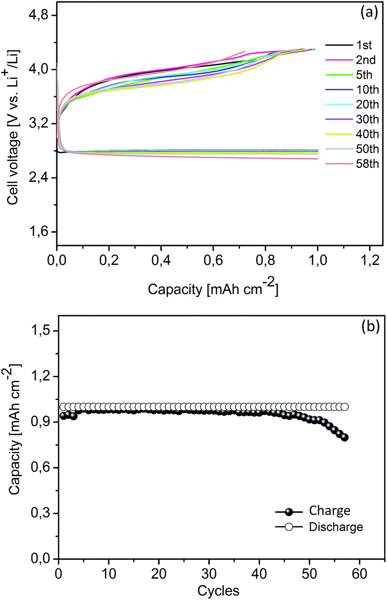
The mesoporous Co3O4, simply synthesized as described in our previous work, has been used at the cathode to improve the cycling performance of Li–O2 cells with TEGDME electrolyte.24 Herein, a Li–O2 cell with a Co3O4 cathode was galvanostatically cycled from 2.25 V to 4.30 V at a current density of 0.1 mA cm−2 with a cut-off capacity of 1.0 mA h cm−2, in order to study the effect of Co3O4 in the DMSO electrolyte. Compared with the Csw cathode, the presence of Co3O4 has no remarkable effect on reducing the charge overpotentials (in Fig. 4b and 5a). However, according to our previous work, the presence of Co3O4 in oxygen cathodes can significantly lower the charge voltage in the TEGDME based electrolyte.24 The different behaviour of the Co3O4 observed in these two electrolytes may result from the electrocatalysis influenced by the nature of the non-aqueous solvents. In the high donor number solvents, such as DMSO, it proceeds through an outer Helmholtz plane (OHP) reaction pathway, conforming to a homogeneous catalysis of the reaction, irrespective of the presence of a catalyst in the cathode.33 Hence, the catalytic activity of the Co3O4 was not significant in the DMSO based electrolyte. However, the presence of Co3O4 improved the cycle life of the Li–O2 cell in the DMSO electrolyte, which increased up to 57 cycles with a reversible capacity of more than 80%, as illustrated in Fig. 5b. The polarization of the discharge and recharge profiles was not noticeable until the 50th cycle. After the cycling test, this cathode was recovered and examined by XRD and FESEM. As shown in Fig. S3 (ESI†), the Co3O4 nanoparticles in the cathode maintained the structure and morphology during the test.
 |
| | Fig. 5 Cyclic performance of a Li–O2 cell with a catalyzed cathode using DMSO electrolyte: (a) cycling response; (b) capacities vs. cycle number. Limited discharge capacity: 1.0 mA h cm−2. Current rate: 0.1 mA cm−2. | |
In order to study the effect of the blended electrolytes, three cells with the carbon cathodes were studied in the EMITFSI–TEGDME and EMITFSI–DMSO mixed electrolytes, respectively. The weight percentage of the EMITFSI added into the TEGDME or DMSO was 20 wt%. As shown in Fig. S4a (ESI†), the EMITFSI–TEGDME electrolyte cannot improve the cycling performance of the Li–O2 cell, compared to the single TEGDME electrolyte (see Fig. 4a). Whereas, Fig. S4b (ESI†) displays that the EMITFSI–DMSO electrolyte significantly enhanced the cycle ability and lowered the voltage gap between the discharge and charge processes, compared to the one with the DMSO electrolyte (in Fig. 4b). Hence, the DMSO based mixture is considered more promising as the electrolyte for Li–O2 cells. Two cells with Co3O4 cathodes were cycled in the TEGDME–DMSO and EMITFSI–DMSO with 0.5 M LiClO4. The weight percentage of the TEGDME or EMITFSI added into the DMSO was 20 wt%. As shown in Fig. 6a, no improvement in the voltage profiles was observed in the cell with the TEGDME–DMSO electrolyte during the first two cycles, compared to the one with the DMSO electrolyte. Then, the charge plateau stood at 3.5 V, resulting in a lower voltage gap and higher energy efficiency. However, the cell with blended electrolyte performed only 50 cycles (in Fig. 6c). Hence, the blended TEGDME–DMSO electrolyte is not considered favourable for the highly reversible Li–O2 cells. Conversely, the cell with EMITFSI–DMSO electrolyte demonstrated a remarkable improvement on the cycling performance. In such an organic solvent-rich mixed electrolyte, the high Gutmann donor number of DMSO can lower the Lewis acidity of solvated Li+ and make it a softer Lewis acid by forming (DMSO)nLi+. Such characteristic of DMSO affords better stability to the one-electron reduction product LiO2 (reaction (3)). The LiO2 may be further reduced to Li2O2 via chemical disproportionation (reaction (4)). At lower discharge potential, LiO2 can be electrochemically reduced to Li2O2 (reaction (5)). Further reduction of Li2O2 to Li2O may be possible from the thermodynamic view (reaction (6)). During the charge process, LiO2 and Li2O2 can be oxidized with no evidence for the step of superoxide intermediate formation (reactions (7) and (8)):11,16
 |
| | Fig. 6 Cyclic performance of Li–O2 cells with catalyzed cathodes: (a) using DMSO–TEGDME electrolyte; (b) using DMSO–EMITFSI electrolyte; (c) discharge capacities (hollow circle)/charge capacities (solid circle) vs. cycle number profiles in various electrolytes. Limited discharge capacity: 1.0 mA h cm−2. Current rate: 0.1 mA cm−2. | |
Oxygen reduction reactions:
| | |
LiO2 + Li+ + e− → Li2O2
| (5) |
| | |
Li2O2 + 2Li+ + 2e− → 2Li2O
| (6) |
Oxygen evolution reactions:
| | |
Li2O2 → O2 + 2Li+ + 2e−
| (8) |
From Fig. 6b, the cell discharged at the constant voltage of 2.75 V until the 50th cycle down to the terminal value of 2.55 V until the end. The charge plateau decreased from 3.80 V to 3.55 V during the first 5 cycles, then steadily increased to 3.85 V until the 60th cycle and subsequently climbed to 3.98 V before cell termination. Compared to the cells with the single-solvent EMITFSI or DMSO electrolyte, the cell with such a blended electrolyte exhibited a lower voltage gap and 80% of the charge process took place underneath 4.0 V. Such outstanding discharge/charge performance is attributed to the synergistic effect of the blend. The addition of EMITFSI significantly improved the ionic conductivity of electrolyte, from 6.1 mS cm−1 for the DMSO electrolyte increased to 9.5 mS cm−1 for the EMITFSI–DMSO electrolyte. The organic solvent has covalent bonds and few ions (by auto-ionization) and hence a lower conductivity. Whereas, the ionic liquids are rich of ions and have a higher conductivity than the organic solvents. With increasing the percentage of IL in organic electrolyte, the conductivity increases quickly until 50 wt% IL and then decreases with further IL increase. The correlation between the conductivity and viscosity of such mixed electrolytes is not followed by the mixtures trend. The viscosity increases very slowly before 40 wt% IL and then rapidly rises after this.21,34,35 Therefore, the addition of 20 wt% IL into the mixed electrolyte compromised the ionic conductivity and viscosity, in order to get a high mass transfer rate. Furthermore, pure EMITFSI possesses high O2 solubility and its addition could increase the O2 concentration in the mixed electrolyte. Fig. 6c presents the discharge/charge capacities versus the cycle number for the cell with EMITFSI–DMSO electrolyte. More than 65 cycles were observed with a discharge capacity of 835 mA h gelectrode−1. The improvement in cell life was 15 cycles, corresponding to an operating time of about 300 h, compared to the cell using the sole DMSO electrolyte. The discharge and recharge overvoltages were significantly reduced using the mixed electrolyte. With this mixed electrolyte, the decomposition of DMSO can be partly mitigated since the recharge can be completed at a lower voltage. In addition, the improved reversibility could be partly related to the higher stability of the mixed electrolyte. In such a mixture, part of the DMSO molecules are supposed to accommodate in the ionic liquid structure, inhibiting the attack provoked by the superoxide.22
Eventually, it is essential to mention that the deterioration of Li anode strongly affects the capacity decay and the cell life span. Firstly, the electrolyte is inevitably saturated with O2, which leads to the corrosion of Li metal through the chemical reaction (9):
Secondly, the commercial solvents contain a certain amount of moisture (<50 ppm) or may gain water from the decomposition of the electrolyte. Under the attack of O2−, part of the DMSO could release O2H through reaction (1), which continues to degrade and form H2O:
The moisture can lead to side reactions on the Li anode due to the non-electrochemical side reactions:
| | |
2Li + 2H2O → 2LiOH + H2
| (13) |
The cell using DMSO–EMITFSI electrolyte (in Fig. 6b) was dissembled after cycling test and the anode was studied by FESEM and XRD. As can be seen from Fig. S5a (ESI†), the Li foil anode has a quite rough surface and appears white powder after the cycling test. Further XRD analysis confirmed that most of the metallic lithium was converted to LiOH after the cycling test (Fig. S5b (ESI†)). Hence, the contribution of the anode degradation to the cell failure is quite noteworthy.
Conclusions
The selection of a stable electrolyte is essential to address the limited cycling ability of the aprotic Li–O2 cells. An optimized LiClO4/EMITFSI–DMSO electrolyte has been proposed and investigated for the rechargeable cell, due to the interesting physical and chemical properties of both solvents. The addition of IL into the DMSO electrolyte can significantly improve the ionic conductivity. Such a mixed electrolyte guaranteed a low charge overpotential, which can moderate the decomposition of DMSO. A Li–O2 cell using the EMITFSI–DMSO electrolyte exhibited a low voltage gap between the charge and discharge processes, resulting in a high-energy efficiency. More than 65 cycles were performed maintaining a satisfactory discharge capacity without significant polarization increase. The results herein suggest that the mixed EMITFSI–DMSO electrolyte could be a feasible solution for developing reversible Li–O2 batteries.
Acknowledgements
Financial support was provided by the European Union Seventh Framework Programme (FP7/2007–2013) project STABLE (no. 314508). The Authors sincerely thank Dr Giuseppina Meligrana for XRD and Mr Mauro Raimondo for FESEM analyses.
Notes and references
- K. M. Abraham and Z. Jiang, J. Electrochem. Soc., 1996, 143, 1–5 CrossRef CAS PubMed.
- J. Lu, Y. Qin, P. Du, X. Luo, T. Wu, Y. Ren, J. Wen, D. J. Miller, J. T. Millera and K. Amine, RSC Adv., 2013, 3, 8276–8285 RSC.
- B. Sun, X. Huang, S. Chen, J. Zhang and G. Wang, RSC Adv., 2014, 4, 11115–11120 RSC.
- J. Read, J. Electrochem. Soc., 2002, 149, A1190–A1195 CrossRef CAS PubMed.
- S. D. Beattie, D. M. Manolescu and S. L. Blair, J. Electrochem. Soc., 2009, 156, A44–A47 CrossRef CAS PubMed.
- X. H. Yang, P. He and Y. Y. Xia, Electrochem. Commun., 2009, 11, 1127–1130 CrossRef CAS PubMed.
- C. Tran, X. Q. Yang and D. Qu, J. Power Sources, 2010, 195, 2057–2063 CrossRef CAS PubMed.
- F. Mizuno, S. Nakanishi, Y. Lotani, S. Yokoishi and H. Iba, Electrochemistry, 2010, 78, 403–405 CrossRef CAS PubMed.
- J. Xiao, J. Hu, D. Wang, D. Hu, W. Xu, G. L. Graff, Z. Nie, J. Liu and J. G. Zhang, J. Power Sources, 2010, 196, 5674–5678 CrossRef PubMed.
- S. A. Freunberger, Y. Chen, Z. Peng, J. M. Griffin, L. J. Hardwick, F. Bardé, P. Novak and P. G. Bruce, J. Am. Chem. Soc., 2011, 133, 8040–8047 CrossRef CAS PubMed.
- C. Ó. Laoire, S. Mukerjee, E. J. Plichta, M. A. Hendrickson and K. M. Abraham, J. Electrochem. Soc., 2011, 158, A302–A308 CrossRef CAS PubMed.
- H. G. Jung, J. Hassoun, J. B. Park, Y. K. Sun and B. Scrosati, Nat. Chem., 2012, 4, 579–585 CrossRef CAS PubMed.
- S. A. Freunberger, Y. Chen, N. E. Drewett, L. J. Hardwick, F. Bardé and P. G. Bruce, Angew. Chem., Int. Ed., 2011, 50, 8609–8613 CrossRef CAS PubMed.
- D. Xu, Z. L. Wang, J. J. Xu, L. L. Zhang and X. B. Zhang, Chem. Commun., 2012, 48, 6948–6950 RSC.
- Z. Peng, S. A. Freunberger, Y. Chen and P. G. Bruce, Science, 2012, 337, 563–566 CrossRef CAS PubMed.
- M. J. Trahan, S. Mukerjee, E. J. Plichta, M. A. Hendrickson and K. M. Abraham, J. Electrochem. Soc., 2013, 160, A259–A267 CrossRef CAS PubMed.
- T. Kuboki, T. Okuyama, T. Ohsaki and N. Takami, J. Power Sources, 2005, 146, 766–769 CrossRef CAS PubMed.
- C. J. Allen, S. Mukerjee, E. J. Plichta, M. A. Hendrickson and K. M. Abraham, J. Phys. Chem. Lett., 2011, 2, 2420–2424 CrossRef CAS.
- F. Mizuno, K. Takechi, S. Higashi, T. Shiga, T. Shiotsuki, N. Takazawa, Y. Sakurabayashi, S. Okazaki, I. Nitta, T. Kodama, H. Nakamoto, H. Nishikoori, S. Nakanishi, Y. Kotani and H. Iba, J. Power Sources, 2013, 228, 47–56 CrossRef CAS PubMed.
- L. Cecchetto, M. Salomon, B. Scrosati and F. Croce, J. Power Sources, 2012, 213, 233–238 CrossRef CAS PubMed.
- B. G. Kim, J. N. Lee, D. J. Lee, J. K. Park and J. W. Choi, ChemSusChem, 2013, 6, 443–448 CrossRef CAS PubMed.
- A. Khan and C. Zhao, Electrochem. Commun., 2014, 49, 1–4 CrossRef CAS PubMed.
- J. Zeng, J. R. Nair, C. Francia, S. Bodoardo and N. Penazzi, Int. J. Electrochem. Sci., 2013, 8, 3912–3927 CAS.
- J. Zeng, C. Francia, J. Amici, S. Bodoardo and N. Penazzi, J. Power Sources, 2014, 272, 1003–1009 CrossRef CAS PubMed.
- R. E. Williford and J. G. Zhang, J. Power Sources, 2009, 194, 1164–1170 CrossRef CAS PubMed.
- E. Nasybulin, W. Xu, M. H. Engelhard, Z. Nie, S. D. Burton, L. Cosimbescu, M. E. Gross and J. G. Zhang, J. Phys. Chem. C, 2013, 117, 2635–2645 CAS.
- H. Lee, D. J. Lee, J.-N. Lee, J. Song, Y. Lee, M.-H. Ryou, J.-K. Park and Y. M. Lee, Electrochim. Acta, 2014, 123, 419–425 CrossRef CAS PubMed.
- C. O. Laoire, S. Mukerjee, K. M. Abraham, E. J. Plichta and M. A. Hendrickson, J. Phys. Chem. C, 2010, 114, 9178–9186 CAS.
- J. R. Nair, C. Gerbaldi, M. Destro, R. Bongiovanni and N. Penazzi, React. Funct. Polym., 2011, 71, 409–416 CrossRef CAS PubMed.
- J. Zeng, J. R. Nair, C. Francia, S. Bodoardo and N. Penazzi, Solid State Ionics, 2014, 262, 160–164 CrossRef CAS PubMed.
- W. Xu, J. Hu, M. H. Engelhard, S. A. Towne, J. S. Hardy, J. Xiao, J. Feng, M. Y. Hu, J. Zhang, F. Ding, M. E. Gross and J. G. Zhang, J. Power Sources, 2012, 215, 240–247 CrossRef CAS PubMed.
- H. G. Jung, H. S. Kim, J. B. Park, I. H. Oh, J. Hassoun, C. S. Yoon, B. Scrosati and Y. K. Sun, Nano Lett., 2012, 12, 4333–4335 CrossRef CAS PubMed.
- M. J. Trahan, I. Gunasekara, S. Mukerjee, E. J. Plichta, M. A. Hendrickson and K. M. Abraham, J. Electrochem. Soc., 2014, 161, A1706–A1715 CrossRef CAS PubMed.
- A. Guerfi, M. Dontigny, P. Charest, M. Petitclerc, M. Lagacé, A. Vijh and K. Zaghib, J. Power Sources, 2010, 195, 845–852 CrossRef CAS PubMed.
- R. S. Kühnel, N. Böckenfeld, S. Passerini, M. Winter and A. Balducci, Electrochim. Acta, 2011, 56, 4092–4099 CrossRef PubMed.
Footnote |
| † Electronic supplementary information (ESI) available: Cyclic performance of Li–O2 cells with carbon cathodes using TEGDME–EMITFS electrolyte and DMSO–EMITFSI electrolyte. FESEM and XRD study of the post-mortem anode of the cell using DMSO–EMITFSI electrolyte after cycling test. See DOI: 10.1039/c5ra13483h |
|
| This journal is © The Royal Society of Chemistry 2015 |
Click here to see how this site uses Cookies. View our privacy policy here.