DOI:
10.1039/C5RA13324F
(Paper)
RSC Adv., 2015,
5, 74592-74604
Synthesis, properties and thermal behavior of poly(decylene-2,5-furanoate): a biobased polyester from 2,5-furan dicarboxylic acid†
Received
7th July 2015
, Accepted 27th August 2015
First published on 27th August 2015
Abstract
In the present study, an interesting, eco-friendly polyester, poly(decylene-2,5-furanoate) (PDeF) was synthesized from 2,5-furan dicarboxylic acid with a variation of the well-known two-step melt polycondensation method. The crystallization and melting behavior of PDeF, was evaluated with different calorimetric methods; conventional, fast and temperature modulated scanning calorimetry. The results showed that PDeF is a fast crystallizing polyester, with a glass transition close to 1 °C and an equilibrium melting temperature equal to 129.8 °C. Various crystallization temperatures and rates were employed in order to evaluate in detail the thermal characteristics of PDeF. Isothermal and non-isothermal crystallization kinetics were also investigated by means of Avrami, Lauritzen–Hoffman theories and model-free kinetics. The structural features of PDeF were also studied by X-ray diffraction (XRD) and nuclear magnetic resonance (1H-NMR) while the size and density of spherulites was observed by polarized optical microscopy (POM) after crystallization in a wide range of temperatures. Finally, from tensile testing it was realized that PDeF has similar mechanical properties like tensile strength and Young's modulus to that of low density polyethylene (LDPE).
1. Introduction
Βiomass-derived polyesters like poly(lactic acid) (PLA), poly(butylene succinate) (PBSu), etc., are among the most promising biodegradable polymers. However, their cost is currently high and their uses are still limited since their properties do not meet demands, so as to replace fossil based polymers in practice. Therefore, there is a need for polyesters prepared from monomers derived from renewable resources, which possess adequate properties.1 Although the prices of the monomers and oligomers which are currently used as building blocks for those bio-based materials is still high, the continuously growing research efforts are expected to contribute to the lowering of those costs. The biorefinery concept seems to be answer to the problem.2
Recently, monomers derived from furfural or hydroxymethylfurfural (HMF), readily available from saccharide sources, exhibit an increasing interest as they simulate the ones prepared from petrol and carbon chemistry.3,4 Novel approaches to the preparation of hydroxymethylfurfural, open the way to the large-scale production of FDCA which is used for the production of poly(ethylene-2,5-furandicarboxylate) (PEF).5–11 2,5-furandicarboxylic acid is one of the most important monomers derived from HMF. The structural similarities of FCDA to its aromatic counterparts, enables it to synthesize polymers via step-growth mechanisms.12 Besides, their similar structure, some differences in their ring size and their polarity can attribute different characteristics to FCDA and terephthalic acid (TA)-based polyesters.13–15 For example the interatomic distance between carboxylic acid groups is 4.830 Å in FCDA, which is shorter than 5.731 Å in TA. Furthermore, the linear p-phenyl connection in TA results in an angle of 180° between carboxylic acid carbons, while the nonlinear structure of FCDA presents an angle of 129.4°.16
Poly(ethylene furanoate) (PEF) is the furan-based analogue to poly(ethylene terephthalate) (PET), which is the dominant polymer used in the beverage packaging industry.17 A significant reduction in oxygen permeability of 11× and in CO2 permeability of 19× at 35 °C, was observed for PEF, compared to poly(ethylene terephthalate) (PET), and was attributed primarily to reduction in chain segment mobility, resulting from a hindrance of furan ring flipping.18,19 PEF also exhibits a ∼5× reduction in water diffusion coefficient averaged over the entire concentration interval compared to PET.20
A survey in the literature shows an increasing research interest in synthesis and properties of FDCA polyesters. So far, the synthesis of a series of poly(2,5-furan dicarboxylate)s based on a variety of diols was reported by Gandini et al.12 Bio-based furanic polyesters or copolyesters with ethylene glycol or other diols have been also reported recently.21–28 However, long chain glycols were not systematically used as monomers for the synthesis of furan based polyesters. In this context, 1,10-decamethylene glycol was combined in this research with 2,5-furandicarboxylic acid to prepare the corresponding bio-based thermoplastic polyester. As was shown in previous studies, furanic polyesters from aliphatic diols with low number of methylene groups are slowly crystallizing and always result in amorphous specimens, unless an annealing treatment is applied.29
The aim of the present work was to evaluate the synthesis of furan-based polyester using an aliphatic diol with long methylene groups (10 –CH2–) sequence in its molecule. The mechanical properties, crystalline structure and thermal behavior of PDeF were studied. Furthermore, in the present study, advanced thermal analysis techniques like temperature-modulated and fast scanning calorimetry were utilized in order to study the thermal transitions in this model furan-based polymer. A thorough comparison of its behavior with traditional thermoplastics used in packaging and other applications or with the behaviors of other members of the furanoates family, currently studied by our groups, has also been performed.
2. Materials and methods
2.1. Materials
2,5-Furan dicarboxylic acid (purum 97%), 1,10-decanediol (1,10-DD) (98%, m.p. = 71–75 °C and b.p. = 297 °C), and tetrabutyl titanate (TBT) catalyst of analytical grade were purchased from Aldrich Co. All other materials and solvents used were of analytical grade.
2.2. Synthesis of 2,5-dimethylfuran-dicarboxylate (DMFD)
15.6 g of 2,5-furandicarboxylic acid, 200 mL of anhydrous methanol and 2 mL of concentrated sulfuric acid were transferred into a round bottom flask (500 mL) and the mixture was refluxed for 5 hours. The excess of the methanol was distilled and the solution was filtered through a disposable Teflon membrane filter. During filtration dimethylester was precipitated as white powder and after cooling 100 mL of distilled water was added. The dispersion was partially neutralized by adding Na2CO3 5% w/v during stirring while pH was measured continuously. The white powder was filtered and the solid was washed several times with distilled water and dried. The isolated white dimethylester was recrystallized with a mixture of 50/50 v/v methanol–water. After cooling 2,5-dimethylfuran-dicarboxylate (DMFD) was precipitated in the form of white needles. The reaction yield was calculated at 83%.
2.3. Polyester synthesis
PDeF polyester was prepared by applying a variation of the two-stage melt polycondensation method (esterification and polycondensation) in a glass batch reactor.30 DMFD and the diol at a molar ratio of diester/diol = 1/2 were charged into the reaction tube of the polyesterification apparatus with 400 ppm TBT. The reaction mixture was heated at 150 °C under argon atmosphere for 2 h, at 160 °C for additional 2 h and finally at 170 °C for 1 h. This first step (transesterification) is considered to complete after the collection of almost all the theoretical amount of CH3OH, which was removed from the reaction mixture by distillation and collected in a graduate cylinder. After this stage the corresponding bishydroxydecylene-2,5-furan carboxylate monomers have been formed. In the second stage these monomers reacted with DMFD in a molar ratio 1/1.05 at 150 °C under argon atmosphere for 2 h, at 160 °C for additional 2 h and finally at 170 °C for 1 h. During this stage methanol was also removed as by-product. After that time in the third step of polycondensation a vacuum (5.0 Pa) was applied slowly over a period of time of about 30 min. The temperature was increased to 210 °C and the polymerization continued for 1 h at this temperature, at 220 °C for 1 h and 230 °C for 0.5 h using a stirring speed 720 rpm. After the polycondensation reaction was completed, the polyester was easily removed, milled and washed with methanol.
2.4. Polyester characterization
2.4.1. Intrinsic viscosity and molecular weight measurements. Intrinsic viscosity [η] measurements of prepared polyester were performed using an Ubbelohde viscometer at 30 °C in a mixture of phenol–1,1,2,2-tetrachloroethane (60/40 w/w). The sample was maintained in the above mixture of solvents at 90 °C for some time to achieve a complete solution. The solution was then cooled to room temperature and filtered through a disposable membrane filter made from Teflon.31 The number-average molecular weight (Mn) of PDeF was measured by Gel permeation chromatography (GPC) using a Waters 150οC apparatus equipped with differential refractometer as detector and three ultrastyragel (103, 104, 105 Å) columns in series. Tetrahydrofuran was used as mobile phase at a flow rate 0.5 mL min−1 at 40 °C. Calibration was performed using polystyrene standards with a narrow molecular weight distribution.
2.4.2. Nuclear magnetic resonance (1H-NMR). 1H-NMR spectrum of PDeF polyester was obtained with a Bruker spectrometer operating at a frequency of 400 MHz for protons. Deuterated trifluoroacetic acid (dTFA) was used as solvent in order to prepare solutions of 5% w/v. The number of scans was 10 and the sweep width was 6 kHz.
2.4.3. Wide angle X-ray diffraction patterns (WAXD). X-ray diffraction measurements of PDeF were performed using a MiniFlex II XRD system from Rigaku Co, with CuKα radiation (λ = 0.154 nm), in the 2θ range from 5 to 60 degrees.
2.4.4. Differential scanning calorimetry (DSC). Thermal analysis studies were carried out using a TA Instruments temperature modulated DSC (TA Q2000). The instrument was calibrated with indium for the heat flow and temperature, while the heat capacity was evaluated using a sapphire standard. Nitrogen gas flow of 50 mL min−1 was purged into the DSC cell. The sample mass was kept around 5 mg in crystallization kinetics tests. The Al sample and reference pans are of identical mass with an error of ±0.01 mg. The temperature modulated DSC scans (TMDSC) were performed at a heating rate of 5 °C min−1, with temperature modulation amplitude of 1 °C and period of 60 s. ICTAC kinetics committee recommendations for collecting thermal analysis data for kinetic computations and for performing kinetic computations on thermal analysis data were followed.32,33 The samples were cooled to 0 °C and then heated at a rate of 20 °C min−1 at temperatures 40 °C higher than the melting temperature. In order to obtain amorphous materials, the samples were held there for 5 min, in order to erase any thermal history, before cooling in the DSC with the highest achievable rate.34Isothermal crystallization experiments of the polymers at various temperatures below the melting point were performed after self-nucleation of the polyester sample. Self-nucleation measurements were performed in analogy to the procedure described by Fillon et al.35 The protocol used by the authors was very similar with that described in previous works from the group36 and to that by Müller et al.37 and can be summarized as follows: (a) melting of the sample at 40 °C above the observed melting point for 5 min to erase any previous thermal history; (b) cooling at 10 °C min−1 to a reference temperature and crystallization, to create a ‘‘standard’’ thermal history; (c) partial melting by heating at 20 °C min−1 up to a “self-nucleation temperature”, Ts; (d) thermal conditioning at Ts for 5 min. Depending on Ts, the crystalline polyester will be completely molten, only self-nucleated or self-nucleated and annealed. If Ts is sufficiently high, no self-nuclei or crystal fragments can remain (Ts Domain I – complete melting domain). At intermediate Ts values, the sample is almost completely molten, but some small crystal fragments or crystal memory effects remain, which can act as self-nuclei during a subsequent cooling from Ts (Ts Domain II – self-nucleation domain). Finally, if Ts is too low, the crystals will only be partially molten, and the remaining crystals will undergo annealing during the 5 min at Ts, while the molten crystals will be self-nucleated during the following cooling, (Ts Domain III – self-nucleation and annealing domain); (e) cooling scan from Ts at 200 °C min−1 to the crystallization temperature (Tc), where the effects of the previous thermal treatment will be reflected on isothermal crystallization; (f) heating scan at 20 °C min−1 to 40 °C above the melting point, where the effects of the thermal history will be apparent on the melting signal. Experiments were performed to check that the sample did not crystallize during the cooling to Tc and that a full crystallization exothermic peak was recorded at Tc. In heating scans after isothermal crystallization the standard heating rate was 20 °C min−1.
2.4.5. Fast scanning calorimetry. Fast scanning calorimetry (FSC) experiments were conducted on a Mettler-Toledo Flash DSC1, using the UFS1 chip calorimeter. Each sensor has a specific serial number and is internally calibrated by Mettler-Toledo. Then, this number is entered in the STAR© software for data evaluation. Calibration was also checked by using indium samples. Small PDeF samples were gently cut by microtome and placed directly on the sample area of the sensor while the reference area remains free. A first heating was done to 160 °C in order to melt the PDeF sample and to spread it uniformly onto the sensor with the help of a very thin brush. Such procedure allows obtaining a thin layer of PDeF on the sensor and homogeneous heating/cooling are thus expected. In a typical run, the PDeF was heated to 160 °C and kept at this temperature for 30 seconds, to ensure complete melting and to erase thermal history. The PDeF sample was cooled from 160 °C to −80 °C at different cooling rates (0.1 °C s−1, 1 °C s−1, 10 °C s−1, 100 °C s−1, 1000 °C s−1). After each cooling, the subsequent heating scans were performed at 1000 K s−1. For better scanning rate performance and heat diffusion, the measurements were conducted under nitrogen flow (∼30 mL min−1).
2.4.6. Polarizing light optical microscopy (PLOM). A polarizing light optical microscope (Nikon, Optiphot-2) equipped with a Linkam THMS 600 heating stage, a Linkam TP 91 control unit and also a Jenoptic ProgRes C10Plus camera with the Capture Pro 2.1 software was used for PLM observations.
2.4.7. Thermogravimetric analysis (TGA). Simultaneous TG/DTA (thermogravimetry/differential thermal analysis) measurements were carried out by a STA 449C (Netzch-Gerätebau, GmbH, Germany) thermal analyzer. The heating range was from room temperature up to 600 °C, with a heating rate of 10 °C min−1 in N2 (99.9%) constant flow of 30 cm3 min−1.
2.4.8. Mechanical properties. Measurements of tensile mechanical properties of the prepared PDeF polyester were performed on an Instron 3344 dynamometer, in accordance with ASTM D638, using a crosshead speed of 50 mm min−1. Thin films of about 350 ± 25 μm were prepared using an Otto Weber, Type PW 30 hydraulic press, at a temperature of 200 ± 2 °C. The moulds were rapidly cooled by immersing them in water at 20 °C. From these films, dumb-bell-shaped tensile test specimens (central portions 5 × 0.5 mm thick, 22 mm gauge length) were cut in a Wallace cutting press and conditioned at 25 °C and 55–60% relative humidity for 48 h. From stress–strain curves, the values of tensile strength at yield point and at break, elongation at break and Young's modulus were determined. At least five specimens were tested for each sample and the average values, together with the standard deviations, are reported.
3. Results & discussion
3.1 Structural characteristics and basic properties of PDeF
The PDeF polyester was synthesized following the procedure described in the experimental part. The polyester had IV = 0.47 dL g−1 and its number average molecular weight determined by GPC was Mn = 36![[thin space (1/6-em)]](https://www.rsc.org/images/entities/char_2009.gif) 710 g mol−1. The chemical structure of the polymer was proved by 1HNMR (Fig. 1) since the characteristic peaks were recorded at: 7.26 δ (2H, s) for ‘a’ protons, 4.38 δ (4H, t) for ‘b’ protons, 1.75 δ (4H, q) for ‘c’ protons and 1.31 δ (12H, s) for ‘d’ protons.
710 g mol−1. The chemical structure of the polymer was proved by 1HNMR (Fig. 1) since the characteristic peaks were recorded at: 7.26 δ (2H, s) for ‘a’ protons, 4.38 δ (4H, t) for ‘b’ protons, 1.75 δ (4H, q) for ‘c’ protons and 1.31 δ (12H, s) for ‘d’ protons.
 |
| | Fig. 1 Chemical structure and 1HNMR spectrum of PDeF. | |
This is a clear proof that the used procedure is appropriate for the preparation of polyesters from FDCA and long chain diols, even though 1,10-decanediol has high boiling point and thus is very difficult to be removed during the second stage of melt polycondensation. However, during the used procedure methanol is removed as byproduct and not 1,10-decanediol producing polyester with high molecular weight. PDeF is a semicrystalline polyester and its WAXD pattern can be seen in Fig. 2a. Main reflection peaks appeared at 11.2, 16.7, 21.5, and 23.8°. Additionally, the WAXD patterns of PDeF are compared with that of polyethylene (PE) in Fig. 2a. As it can be seen, PDeF exhibits peaks at 21.5° and 23.8° which correspond to the reflections of the (110) and the (200) crystal planes of the α-crystals of PE. This is a consequence of the long methylene sequences appearing along the PDeF macromolecular chains, inducing similarities in the crystal unit cells with PE. In PDeF, an additional peak was recorded at 16.6° and another of lower intensity at 11.1°. According to Jiang et al.,38 who prepared PDeF of similar molecular weight, the polyester crystallizes in the triclinic β-form.
 |
| | Fig. 2 (a) Comparison of the WAXD patterns of PDeF and polyethylene and (b) TGA and DTG curves for PDeF. | |
The thermal stability of PDeF was studied by using TGA in a N2 atmosphere. Thermal degradation occurred within a range of 120–130 °C, beginning a little above 300 °C (Fig. 2b). A 5% mass loss was observed at 359 °C, while the maximum loss rate was observed at 386 °C. In concurrent studies it was found that the thermal degradation of PEF began about 325 °C, while the temperature for maximum loss rate was 415 °C. For poly(propylene furanoate) (PPF) the temperature for maximum loss rate was 396 °C, while a value of 361 °C was found for poly(butylene furanoate) (PBF).
From the measurements of the mechanical properties of PDeF, it was found that PDeF has tensile strength at yield ranging between 10–12 MPa, tensile strength at break 11–13 MPa and Young's modulus 200–250 MPa. These are similar to the mechanical properties of low density polyethylene (LDPE). However, PDeF has lower elongation at break 130–160%, which could be attributed to its lower molecular weight, compared with LDPE (usually 300000–600000 g mol−1). Such molecular weight is appropriate for the formulation of LDPE into films, mould articles and fibers. The similarities in the properties of these two materials originate from their analogous structural characteristics. Therefore, among the other important characteristics, PDeF could be an environmentally friendly polymer, prepared from fully renewable resources, able to replace LDPE in several commercial and industrial uses.
3.2 Thermal transitions
PDeF was initially studied by using standard DSC in order to observe its thermal characteristics (Fig. 3). The as-received sample was originally heated at 20 °C min−1 and the melting peak was revealed at 116 °C, which is very close to that of LDPE (113–115 °C), indicating once again the capability of PDeF to replace LDPE in several uses. An annealing peak also appeared at 50 °C. Afterwards, the sample was rapidly cooled (quenched) at 80 °C min−1 and the heating trace at 20 °C min−1 revealed the melting peak at a slightly lower temperature than the as-received sample (112 °C), while a re-crystallization peak appeared at 99.5 °C. This value agrees with the melting temperature value, reported recently by Jiang et al.38 Moreover, the melting temperature of PDeF is observed at lower temperatures than the other furanoates with a smaller number of methylene groups, as a result of the chain length of the polyester.29,30,39 From the graphs presented in Fig. 3, it can be understood that the rate of 80 °C min−1 was not fast enough in order to prevent the formation of the crystallites during the cooling procedure, therefore the sample was not completely amorphous. For this reason, fast scanning calorimetry should be utilized in order to obtain a fully amorphous sample.40,41 Finally, after the second heating, the sample was cooled down with an intermediate cooling rate (10 °C min−1) and the crystallization peak was seen at 76 °C.
 |
| | Fig. 3 Standard DSC heating traces of the as received and quenched PDeF sample and DSC cooling traces of the sample cooled at 10 °C min−1. | |
Temperature-modulated DSC was also employed in order to obtain some initial information regarding the thermal characteristics of the quenched sample of PDeF. From the TMDSC traces presented in Fig. 4, apart from the weak signal in the region of 0–10 °C for the glass transition temperature, the most interesting part is the large peaks observed in the non-reversing signal, which indicate the recrystallization phenomena which take place during the heating procedure of the sample. As the cooling rate in the instrument cell cannot be very fast in practice, semicrystalline samples were always obtained, so that the heat capacity increase in the glass transition is small and also the Tg is expected to shift upwards. Once again, the fact that poor crystals were formed during the cooling procedure is obvious since these melt and recrystallize, as it can be seen from the exothermic peaks in the total and non-reversing curve.
 |
| | Fig. 4 TMDSC traces for the quenched sample of PDeF. | |
Fast Scanning Calorimetry (FSC) experiments were conducted on Mettler-Toledo Flash DSC1 using the UFS1 chip calorimeter in order to facilitate the observation of the glass transition temperature. After heating to 160 °C and holding for 30 s, cooling was performed down to −80 °C. Thus, heat-cool cycles were performed. The cooling scans were conducted at different cooling rates (0.1 °C s−1, 1 °C s−1, 10 °C s−1, 100 °C s−1, 1000 °C s−1) in order to determine the critical rate to obtain amorphous samples. The subsequent heating scans at 1000 K s−1 are shown in Fig. 5. Under rather slow cooling (e.g. 0.1 to 10 K s−1), the subsequent heating scans exhibit the melting of PDeF crystals. The PDeF samples were efficiently quenched when a cooling rate higher than 100 °C s−1 was applied since no melting is observed on heating. As shown in Fig. 5, a Tg value of about 1 °C should be adopted. Interestingly, fast cooling and heating (1000 K s−1) are necessary to avoid PDeF physical aging since limited enthalpy relaxation is observed on subsequent heating.
 |
| | Fig. 5 FSC heating traces at 1000 °C s−1 (60000 °C min−1) of samples that were previously cooled from the melt at different cooling rates ranging from 0.1 to 1000 °C s−1 (6–60000 °C min). | |
3.3 Melting behavior
The melting behavior of a polymeric substance can give important information regarding the crystalline structure of the sample and the performance of the material after it has been isothermally or non-isothermally crystallized. PDeF samples were initially crystallized isothermally at different temperatures and then heated with 20 °C min−1 in the standard DSC cell, in order to observe their melting (Fig. 6a). For low crystallization temperatures, the subsequent heating scans depicted multiple melting (3 melting peaks). The low temperature peak I was not well observed, but the whole work evidenced the existence of it. This was most probably the well-known annealing peak, always observed a few degrees above the crystallization temperature for most polyesters suffering annealing.42,43 It is well accepted that in most cases this peak is related with melting of secondary crystals and thinner lamellae.
 |
| | Fig. 6 (a) DSC traces for PDeF crystallized at different temperatures (b) effect of heating rate on the melting behavior of PHF samples crystallized at 90 °C for 20 min. | |
As the temperature increased, the middle temperature peak II dominated, while the ultimate temperature peak III disappeared. The peak II temperature increased with increasing Tc, showing higher stability of the crystals due to their highest perfection. The effect of the heating rate on the melting behavior was also evaluated and the results are presented in Fig. 6b. As it is obvious, in case of the slower heating rates (2.5 and 5 °C min−1), there is enough time for the sample to melt partially and recrystallize, forming this way crystals with high perfection, therefore the sample presents multiple melting behavior, which is typical for polyesters.44–47 In fact, for slow rates, peak III increased in both temperature and heat of fusion. This proved that peak III is associated with melting of the stable crystals generated by recrystallation/reorganization. On the other hand, the faster rates do not allow the sample to develop high enough crystalline perfection, therefore, the melting behavior of the sample is represented by a broadened peak due to superheating.44 After all, it seems that peak II is the one associated with melting of primary crystals formed during the isothermal crystallization stage.
Temperature-modulated DSC (TMDSC) was also employed on PDeF samples, which were isothermally crystallized at three different temperatures, namely 85, 95 and 105 °C (Fig. 7a–c). TMDSC is useful in similar studies, since it can separate events which occur simultaneously during a heating scan.48 Recrystallization is a non-reversible phenomenon; therefore it can be depicted on the non-reversing signal of MDSC. For the sample crystallized at 85 °C, a large exothermic recrystallization peak can be seen in the non-reversing signal along with an endothermic peak which follows. This behavior is consistent with an extensive recrystallization due to the low thermal stability of crystals generated at a low to moderate crystallization temperature. The recrystallized material of high thermal stability melts at higher temperature, as was revealed by the non reversing melting peak. The case was a little different for the sample crystallized at 95 °C. This was a moderate temperature and so crystals of moderate perfection were formed. Therefore, the interesting feature of two non-reversing melting peaks was observed. Each of the non reversing meltings was accompanied by recrystallization. Finally, for the sample crystallized at a high crystallization temperature (105 °C) a large non-reversing melting peak appeared first and then a recrystallization exothermic peak followed. This was consistent with the increased thermal stability of the primary crystals generated during the isothermal stage at 105 °C. Annealing polyesters at high temperatures (within ca. 20 °C of final melting point) results in systems which have high Tm relative to their equilibrium melting point, and a very large non-reversing melting endotherm contribution.49 In general, in this work it was found that for low stability crystals formed at low temperatures the recrystallization peaks appeared first and the non-reversing melting peaks followed. The picture was reversed for samples crystallized at high Tcs, close to the melting temperature.
 |
| | Fig. 7 TMDSC traces of PDeF samples isothermally crystallized at (a) 85 °C, (b) 95 °C and (c) 105 °C. | |
3.4 Isothermal crystallization
The chemical structure of the polymer and the thermal conditions it undergoes, determine the solidification process of the material. The physical structure in its turn determines the properties of the specimen. In the first part of the crystallization study PDeF samples were isothermally crystallized under a wide variety of temperatures ranging from 85 to 107.5 °C. The specific procedure involved heating at temperatures higher than the melting point and then rapidly cooling the melt to the crystallization temperature. The exothermal curves were recorded as a function of time and they are presented in ESI (Fig. 1S†).
Also from the isothermal curves, the evolution of the relative degree of crystallinity as a function of time or temperature can be obtained if an assumption is firstly made, that the evolution of the relative degree of crystallinity is proportional to the evolution of heat which is released during the crystallization phenomenon:
| |
 | (1) |
In eqn (1), dHc denotes the measured enthalpy of crystallization during an infinitesimal time interval dt. The limits t and ∞ on the integrals are used to denote the elapsed time during the course of crystallization and at the end of the crystallization process, respectively. The S-shaped curves of the relative degree of crystallinity versus time are presented in Fig. 8a for PDeF. From the specific graphs, the half-time of crystallization (t1/2) can be exported (ESI Fig. 2S†) as a function of crystallization temperature, a parameter which represents the overall crystallization rate, since it shows the time needed to reach the 50% of crystallization. The higher the t1/2 is, the longer it takes for the sample to crystallize. From the t1/2 values presented in ESI (Fig. 2S†), it is obvious once again that higher crystallization temperatures demand higher times, in order to let the material crystallize.
 |
| | Fig. 8 (a) Evolution of the relative degree of crystallinity versus time for PDeF, (b) results from the application of the Avrami theory. | |
The well-known Avrami theory was also employed on the data from the isothermal crystallization of PDeF. The specific method is based on the primary assumption that the relative degree of crystallinity develops as a function of the crystallization time, as described from the following equation:
| | |
X(t) = 1 −exp(ktn) or X(t) = 1 − exp[−ktn]
| (2) |
where
X(
t) is the relative degree of crystallinity at time
t,
k is the crystallization rate constant which is dependent on the nucleation and growth rate and
n is the Avrami exponent which is dependent on the growth geometry of the crystals and the nature of nucleation. The composite Avrami form involves
K instead of
k (where
k =
Kn). In order to take into account the whole range of crystallization, from the lowest to the highest degree of conversion, a non-linear fitting procedure was followed, based on the algorithm proposed by Levenberg–Marquardt. As it can be seen, the quality of fitting between the experimental results and the application of the Avrami fitting are very good (
R2 > 0.999), therefore the results from the application of the Avrami theory, which are presented in
Fig. 8b can be considered accurate. Some small deviations can appear in the beginning or end of the phenomenon and correspond to very low (<4%) and high (>96%) degrees of crystallinity. The
n values that were found in the case of PDeF are in the vincinity of 2 to 3 for most crystallization temperatures, indicating possible 2-dimensional platelet-like growth or 3-dimensional sphere-like growth. These values increase with increasing crystallization temperature which is an indication that the crystallization is a multi-step process that cannot be completely described by a single-step equation such as Avrami equation. Also, the fact that the rate constant decreases with increasing crystallization temperature, is once again an indication that the process needs more time at higher temperatures.
3.5 Application of secondary nucleation theory
The secondary nucleation theory of Lauritzen–Hoffman can be used for the treatment of the spherulite growth rates. According to this theory, the crystal growth rate G at a specific crystallization temperature can be expressed by the Lauritzen–Hoffman equation:50| |
 | (3) |
where, G0 is the pre-exponential factor, the first exponential term contains the contribution of diffusion process to the growth rate, while the second exponential term is the contribution of the nucleation process; U* denotes the activation energy which characterizes molecular diffusion across the interfacial boundary between melt and crystals, usually set equal to 1500 cal mol−1 and T∞ is the temperature below which diffusion stops, usually equal to T∞ = Tg − 30 K; Kg is a nucleation constant and ΔT denotes the degree of undercooling (ΔT = T0m − Tc); f is a correction factor which is close to unity at high temperatures and is given as f = 2Tc/(T0m + Tc).50 The equilibrium melting point of POF was set equal to 129.8 °C and the glass transition temperature was set equal to 1 °C. The above mentioned equation can be also written in its logarithmic form and the growth rate G can be obtained from an approximation, where G is equal to the inverse of the half time of crystallization (G ≈ 1/t1/2).51–54
Fig. 9 shows the relationship between log + U*/[2.3R(Tc − T∞)] and 1/[Tc(ΔT)f]. In Fig. 9 each straight line corresponds to a different crystallization regime and the slope of each line is equal to Kg for the corresponding regime. At 94 °C, breakpoint was observed, most probably corresponding to the transition from regime II to regime I for PDeF. The calculated values of the nucleation constant Kg for each crystallization regime can be seen in Fig. 9, while the relationship between the Kg parameters is close to the theoretic prediction of KgI = 2KgII. Furthermore, it was found that KgII = 2.05 × 10⁵ K2 for PEF, KgII = 1.03 × 10⁵ K2 for PBF. For poly (hexamethylene furanoate) it was found that KgI = 1.76 × 10⁵ and KgII = 0.9 × 105.39 The lower values of Kg were expected for PDeF, since the high number of methylene units, increases the flexibility of the macromolecular chains, compared to the other samples.
 |
| | Fig. 9 Lauritzen–Hoffman plots for PDeF. | |
3.6 Equilibrium melting temperature
Several methods have been proposed for the estimation of the equilibrium melting temperature of polymeric substances. One of them is the extrapolative method proposed by Hoffman and Weeks,55 which uses the melting temperature of the polymer versus the crystallization temperature and from the linear extrapolation to the line Tc = Tm, the T0m can be found in the point of intersection. The reliability of the specific method has been debated by other works56 since it assumes that the thickening coefficient which is included in the H–W equation is independent of the crystallization temperature and time and the lateral dimensions must be significantly higher than the thickness of lamellae. Therefore we can say that it provides a rough estimation of the T0m. The equation which describes the Hoffman–Weeks theory is:| |
 | (4) |
where Tm represents the melting temperature of the crystals formed in different isothermal temperatures Tc and β is the thickening coefficient, equal to Lc/L*c and it indicated the ratio of the thickness of the grown crystallites Lc to that of the initial ones L*c.55. The results from the application of this theory are depicted in Fig. 10a and it can be seen that the equilibrium melting temperature of PDeF was found equal to T0m = 129.8 °C.
 |
| | Fig. 10 Hoffman–Weeks plot for the estimation of the equilibrium melting temperature of PDeF. | |
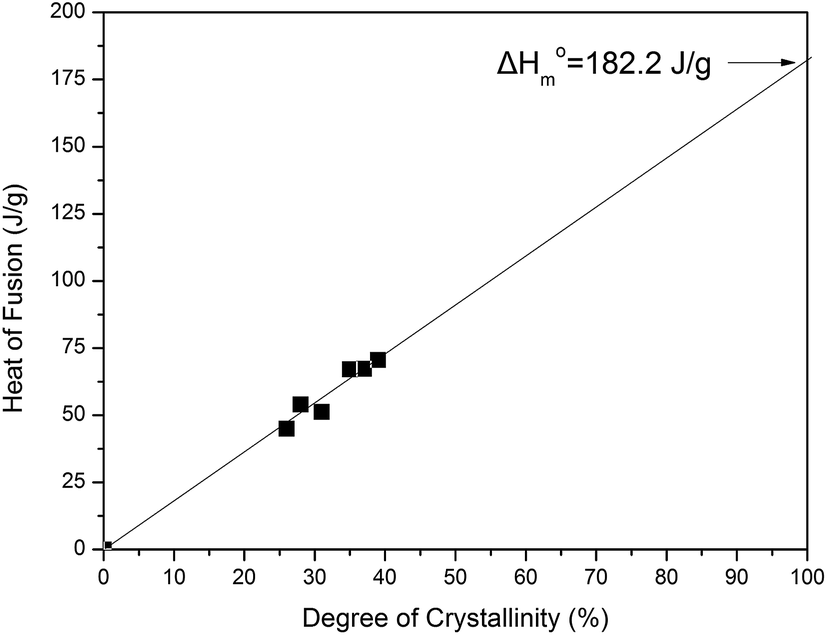
3.7 Enthalpy of fusion of the pure crystalline PDeF
During an attempt to determine the enthalpy of fusion (ΔH0m) of PDeF, the main target was to prepare a series of samples exhibiting different degrees of crystallinity. In fact, the samples were cooled under different conditions in order to obtain different crystallinity values for the PDeF samples. Unfortunately, samples always crystallized significantly, so the differences in the degree of crystallinity were not very large. However, from the DSC traces, the heat of fusion of these samples was measured. The crystallinity values were calculated from the WAXD patterns and the relative areas under the crystalline peaks, Ac, and the amorphous background, Aam, using the following equation:according to Hay et al.57
The plot of the heat of fusion that was measured by DSC as a function of the degree of crystallinity is presented in Fig. 11 and the value of ΔH0m = 182.2 J g−1 was found by an extrapolation to 100% crystallinity. This value is in fact just a first estimation for the heat of fusion for the pure crystalline material. It is lower than that of ΔH0m = 198 J g−1 recently reported by Jiang et al.38 For poly(decamethylene terephthalate) the values of ΔH0m = 151.4 J g−1 and ΔSm = 111.9 J mol−1 K−1 have been reported, after taking into account the group contributions for the calculations.58 Using this value for ΔSm and T0m = 129.8 °C a ΔH0m = 153 J g−1 is reached for PDeF, which seems more reasonable.
 |
| | Fig. 11 Plot of the measured heat of fusion against the degree of crystallinity calculated from WAXD patterns. | |
3.8. Polarized light optical microscopy study
Polarized light optical microscopy (PLOM) was employed for the observation of the spherulitic formation under isothermal crystallization. The specific study showed that even at elevated temperatures, large nucleation density is observed for PDeF (Fig. 12). In fact there were not significant changes in the appearance of the spherulites with varying crystallization temperature. The only difference was in the case of the fast cooled sample, with some indication for slightly larger spherulites. In general, there was no direct evidence for a change of the morphology in the region of 94 °C, where a regime transition was supposed to occur. Very large nucleation density and small spherulite sizes were also observed for almost all the furanoate polyesters studied so far, which in fact had an even number of methylene units in their repeating units. A different case was observed for PPF and poly(2,2-dimethyl propylene furanoate) (PDMPF), where much larger spherulites were formed and the nucleation density was significantly reduced. This seems to be associated with the odd number of methylene groups in their repeating units.
 |
| | Fig. 12 PLOM photographs of PDeF samples recorded at (a) 75 °C, (b) 85 °C, (c) 95 °C, (d) 100 °C, (e) 105 °C and (f) 110 °C after rapid cooling. | |
3.9. Non-isothermal crystallization
Dynamic non-isothermal crystallization is very important in polymer processing such as injection molding and extrusion, therefore the behavior of a material under these conditions should be studied thoroughly. In the present study, PDeF was dynamically crystallized under several cooling rates, ranging from 2.5 to 20 °C min−1, in order to observe the behavior of the sample and export conclusions regarding the kinetics of the process. The non-isothermal exothermic curves of PDeF at various cooling rates are shown in Fig. 13a. The increase of the cooling rates shifts the peaks to lower temperatures, which is common for semicrystalline polymers (Fig. 13b). The slow rates allow the polymer to stay for a long time at the temperature range which promotes the mobility of the segments for the growth of crystallites, while the high rates reduce the mobility of the segments and do not allow the formation of regular crystallites, which has as a result the decrease of the crystallization temperature.59 Furthermore, a decrease in the heat of crystallization was observed with increasing cooling rate (Fig. 13b) showing that the final achievable degree of crystallinity was also reduced. As with isothermal crystallization, the relative degree of crystallinity versus temperature can be obtained from non-isothermal crystallization curves and it is presented in ESI (Fig. 3S†). The time-temperature transformation (t = (T0 − T)/α) can additionally be employed in order to plot the relative degree of crystallinity as a function of time.
 |
| | Fig. 13 (a) DSC traces of non-isothermal crystallization of PDeF, (b) peak temperature and enthalpy of non-isothermal crystallization of PDeF. | |
3.10 Avrami analysis of non-isothermal crystallization
Several macrokinetic theories have been proposed for the analysis of the kinetics of non-isothermal crystallization. One of the most used theories is the one proposed by Avrami,60 which was modified by Jerziorny61 and according to this theory the relative degree of crystallinity can as a function of time can be calculated from:| | |
X = 1 − exp(Zttn) or X = 1 − exp[−(KAt)n]
| (6) |
where Zt and n denote the growth rate constant and the Avrami exponent, while KA is a part of the composite Avrami form, where Zt = KnA. The Avrami parameters can be obtained from the slope and intercept of the linear fitting of log[−ln(1 − X(t))] vs. log(t). The results are presented in ESI (Fig. 4S†) and Table 1. The Avrami exponent values are close to 4, which is an indication of three dimensional growth from the melt, while the Avrami constant values (which are indicative of the crystallization rates) decrease with decreasing cooling rate, a fact which is expected, since supercooling also decreases with decreasing cooling rate.62
Table 1 Results from the Avrami analysis of non-isothermally crystallized PDeF
| Cooling rate (°C min−1) |
Peak temperature (°C) |
Avrami exponent (n) |
Avrami constant Zt (min−n) |
Avrami constant (K) (min−1) |
| 2.5 |
85.8 |
4.2 |
0.00016 |
0.0003 |
| 5 |
81.2 |
4.1 |
0.03 |
0.007 |
| 7.5 |
77.9 |
4.2 |
0.08 |
0.02 |
| 10 |
75.2 |
4.5 |
0.16 |
0.03 |
| 15 |
71.3 |
4.1 |
0.63 |
0.15 |
| 20 |
67.5 |
4.2 |
0.97 |
0.23 |
3.11 Effective activation energy of non-isothermal crystallization
Kissinger's method has been vastly employed in order to calculate the activation energy of a sample crystallized under dynamic conditions.63 However, since Vyazovkin and Sbirrazzuoli exhibited that the use of Kissinger equation cannot be applied to processes that occur on cooling,64 the differential method of Friedman65 and the advanced isoconversional method of Vyazovkin and Sbirrazzuoli66 can be utilized for the calculations of the effective activation energy. Friedman's method is represented by eqn (7):| |
 | (7) |
where dX/dt is the instantaneous crystallization rate as a function of time at a given relative degree of crystallinity X, ΔEX is the effective activation energy at a given degree of crystallinity X, TX,i is the set of temperatures related to a given degree of crystallinity X at different cooling rates, βi and the subscript i refers to every individual cooling rate used. At a fixed degree of crystallinity, the corresponding activation energy can be calculated from the slope of the linear fitting on the plot ln(dXT/dT)XT vs. 1/TX for different cooling rates. It should be noted that the activation energy in this case has the meaning of the temperature coefficient of the crystallization rate.48 This method has been used and compared to the method proposed by Vyazovkin and Sbirrazzuoli.66
Analysis of Fig. 14a and b show that Friedman and Vyazovkin–Sbirrazzuoli methods give comparable results. The shift observed for Friedman's method to lower values is in perfect agreement with results already reported using simulated data67 and is explained by the decrease of crystallization enthalpy with cooling rate (non-constant values). From the results presented in Fig. 14a, it can be seen that the melt crystallization process is very complex and involve at least 3 or 4 different steps. In perfect agreement with the Lauritzen–Hoffman theory of polymer secondary nucleation we obtained negative increasing values of the apparent activation energy (Eα) with relative degree of crystallinity (α), which signify that the crystallization process is controlled by nucleation in this temperature domain.64,66,68–70 The apparent activation energy (Eα) increases with increasing relative degree of crystallinity until α ∼ 0.80, indicating that it is more difficult for the polymer to crystallize as the α increases, while from α > 0.80, there is a drop on the Eα values. A sharp increase is observed for the very beginning of the crystallization 0.02 < α < 0.10. A similar result was already reported for PDMS, PEF and PTFE crystallization from the melt.71–73 After this initial part (α < 0.10), the increase of Eα is lower indicating that it becomes easier for the polymer to crystallize. The apparent activation energy can be also plotted as a function of temperature, by taking an average temperature associated with each value of relative degree of crystallinity (Fig. 14b). Four crystallization steps can be highlighted in this graph. The first one, correspond to a temperature domain ranging from 85 °C (358 K) to about 81 °C (354 K) and correspond to the first crystallization step observed for α < 0.10 with increasing apparent activation energy values. Then, a second region is observed between 81 °C (354 K) and 73 °C (346 K) with a lower increase of apparent activation energy values (0.10 < α < 0.80). The third (0.80 < α < 0.90) and fourth (0.90 < α < 0.98) regions are characterized by decreasing apparent activation energy values from 73 °C (346 K) till 70 °C (343 K) and from 70 °C till 67 °C (340 K). A sharper decrease is observed in the third region (0.80 < α < 0.90). Note that in this temperature domain, which is much higher than the glass transition temperature, positive Eα values characteristic of diffusion control were never reached.
 |
| | Fig. 14 (a) Dependence of the effective activation energy (Eα) on the relative degree of crystallinity (α) and (b) temperature (T). Open triangles: Friedman's method, solid rhombi: Vyazovkin and Sbirrazzuoli's method. | |
4. Conclusions
Poly(decylene-2,5-furanoate) has been successfully synthesized and several basic and advanced characteristics were studied in detail with the employment of a variety of techniques. The melting temperature of PDeF was found equal to 112 °C, while its glass transition was close to 1 °C. The melting behavior of the newly developed polymer was similar to most polyesters, exhibiting the melting-crystallization-remelting phenomenon due to the formation of unstable crystals, during the heating procedure. The equilibrium melting temperature was calculated from Hoffman–Weeks method and it was found equal to 129.8 °C, while the enthalpy of fusion was estimated after obtaining samples with different crystallinity and a value of ΔH0m = 182.2 J g−1 was found for PDeF. However, the value of 153 J g−1calculated from group contributions seems more realistic. Additionally, from the Hoffman–Weeks equation, the calculated Kg values were lower than those for PEF, PBF or PHF due to the increased flexibility of the macromolecular chains of PDeF. Moreover, the large nucleation density of fast-crystallizing polyesters, like the furan-based ones, was realized once again from the polarized light optical microscopy experiments. Finally, PDeF can be easily formulated into films and fibers and exhibits similar tensile strength and Young's modulus as LDPE, which is one of the most extensively used polymers for several applications.
Acknowledgements
Dr N. Guigo and Prof. N. Sbirrazzuoli wish to thank Dr Urs Joerimann, Dr Franck Collas and Laurent Zoppi from Mettler-Toledo Inc. for fruitful collaboration.
References
- C. Vilela, A. F. Sousa, A. C. Fonseca, A. C. Serra, J. F. J. Coelho, C. S. R. Freire and A. J. D. Silvestre, Polym. Chem., 2014, 5, 3119–3141 RSC.
- D. Esposito and M. Antonietti, Chem. Soc. Rev., 2015, 44, 5821–5835 RSC.
- A. Gandini, Polym. Chem., 2010, 1, 245–251 RSC.
- J. Ma, Y. Pang, M. Wang, J. Xu, H. Ma and X. Nie, J. Mater. Chem., 2012, 22, 3457–3461 RSC.
- A. J. J. E. Eerhart, W. J. J. Huijgen, R. J. H. Grisel, J. C. van der Waal, E. de Jong, A. de Sousa Dias, A. P. C. Faaij and M. K. Patel, RSC Adv., 2014, 4, 3536–3549 RSC.
- G. Z. Papageorgiou, V. Tsanaktsis and D. N. Bikiaris, Phys. Chem. Chem. Phys., 2014, 16, 7946–7958 RSC.
- C. Vilela, A. F. Sousa, A. C. Fonseca, A. C. Serra, J. F. J. Coelho, C. S. R. Freire and A. J. D. Silvestre, Polym. Chem., 2014, 5, 3119–3141 RSC.
- M. Jiang, Q. Liu, Q. Zhang, C. Ye and G. Zhou, J. Polym. Sci., Part A: Polym. Chem., 2012, 50, 1026–1036 CrossRef CAS PubMed.
- S. Thiyagarajan, W. Vogelzang, R. J. I. Knoop, A. E. Frissen, J. van Haveren and D. S. van Es, Green Chem., 2014, 16, 1957–1966 RSC.
- H. Ait Rass, N. Essayem and M. Besson, Green Chem., 2013, 15, 2240–2251 RSC.
- T. Wang, M. W. Nolte and B. H. Shanks, Green Chem., 2014, 16, 548–572 RSC.
- M. Gomes, A. Gandini, A. J. Silvestre and B. Reis, J. Polym. Sci., Part A: Polym. Chem., 2011, 49, 3759–3768 CrossRef CAS PubMed.
- G. Z. Papageorgiou, V. Tsanaktsis, D. G. Papageorgiou, S. Exarhopoulos, M. Papageorgiou and D. N. Bikiaris, Polymer, 2014, 55, 3846–3858 CrossRef CAS PubMed.
- G. Z. Papageorgiou, D. G. Papageorgiou, V. Tsanaktsis and D. N. Bikiaris, Polymer, 2015, 62, 28–38 CrossRef CAS PubMed.
- A. Gandini, A. J. Silvestre, C. P. Neto, A. F. Sousa and M. Gomes, J. Polym. Sci., Part A: Polym. Chem., 2009, 47, 295–298 CrossRef CAS PubMed.
- J. Wu, P. Eduard, S. Thiyagarajan, J. van Haveren, D. S. van Es, C. E. Koning, M. Lutz and C. Fonseca Guerra, ChemSusChem, 2011, 4, 599–603 CrossRef CAS PubMed.
- S. Munoz-Guerra, C. Lavilla, C. Japu and A. Martinez de Ilarduya, Green Chem., 2014, 16, 1716–1739 RSC.
- S. K. Burgess, O. Karvan, J. R. Johnson, R. M. Kriegel and W. J. Koros, Polymer, 2014, 55, 4748–4756 CrossRef CAS PubMed.
- S. K. Burgess, R. M. Kriegel and W. J. Koros, Macromolecules, 2015, 48, 2184–2193 CrossRef CAS.
- S. K. Burgess, D. S. Mikkilineni, B. Y. Daniel, D. J. Kim, C. R. Mubarak, R. M. Kriegel and W. J. Koros, Polymer, 2014, 55, 6870–6882 CrossRef CAS PubMed.
- L. Wu, R. Mincheva, Y. Xu, J.-M. Raquez and P. Dubois, Biomacromolecules, 2012, 13, 2973–2981 CrossRef CAS PubMed.
- B. Wu, Y. Xu, Z. Bu, L. Wu, B.-G. Li and P. Dubois, Polymer, 2014, 55, 3648–3655 CrossRef CAS PubMed.
- P. Gopalakrishnan, S. Narayan-Sarathy, T. Ghosh, K. Mahajan and M. Belgacem, J. Polym. Res., 2013, 21, 1–9 Search PubMed.
- N. Jacquel, R. Saint-Loup, J.-P. Pascault, A. Rousseau and F. Fenouillot, Polymer, 2015, 59, 234–242 CrossRef CAS PubMed.
- A. F. Sousa, M. Matos, C. S. R. Freire, A. J. D. Silvestre and J. F. J. Coelho, Polymer, 2013, 54, 513–519 CrossRef CAS PubMed.
- J. G. van Berkel, N. Guigo, J. J. Kolstad, L. Sipos, B. Wang, M. A. Dam and N. Sbirrazzuoli, Macromol. Mater. Eng., 2015, 300, 466–474 CrossRef CAS PubMed.
- M. Vannini, P. Marchese, A. Celli and C. Lorenzetti, Green Chem., 2015, 17, 4162–4166 RSC.
- F. H. Isikgor and C. R. Becer, Polym. Chem., 2015, 6, 4497–4559 RSC.
- G. Z. Papageorgiou, N. Guigo, V. Tsanaktsis, D. G. Papageorgiou, S. Exarhopoulos, N. Sbirrazzuoli and D. N. Bikiaris, Eur. Polym. J., 2015, 68, 115–127 CrossRef CAS PubMed.
- V. Tsanaktsis, G. Z. Papageorgiou and D. N. Bikiaris, J. Polym. Sci., Part A: Polym. Chem., 2015 DOI:10.1002/pola.27730.
- G. P. Karayannidis, G. Z. Papageorgiou, D. N. Bikiaris and E. V. Tourasanidis, Polymer, 1998, 39, 4129–4134 CrossRef CAS.
- S. Vyazovkin, K. Chrissafis, M. L. Di Lorenzo, N. Koga, M. Pijolat, B. Roduit, N. Sbirrazzuoli and J. J. Suñol, Thermochim. Acta, 2014, 590, 1–23 CrossRef CAS PubMed.
- S. Vyazovkin, A. K. Burnham, J. M. Criado, L. A. Pérez-Maqueda, C. Popescu and N. Sbirrazzuoli, Thermochim. Acta, 2011, 520, 1–19 CrossRef CAS PubMed.
- G. Z. Papageorgiou, D. S. Achilias, G. P. Karayannidis, D. N. Bikiaris, C. Roupakias and G. Litsardakis, Eur. Polym. J., 2006, 42, 434–445 CrossRef CAS PubMed.
- B. Fillon, J. C. Wittmann, B. Lotz and A. Thierry, J. Polym. Sci., Part A: Polym. Chem., 1993, 31, 1383–1393 CrossRef CAS PubMed.
- G. Z. Papageorgiou, D. S. Achilias and D. N. Bikiaris, Macromol. Chem. Phys., 2009, 210, 90–107 CrossRef CAS PubMed.
- D. Cavallo, L. Gardella, G. Portale, A. J. Müller and G. C. Alfonso, Polymer, 2013, 54, 4637–4644 CrossRef CAS PubMed.
- Y. Jiang, A. J. J. Woortman, G. O. R. Alberda van Ekenstein and K. Loos, Polym. Chem., 2015, 6, 5198–5211 RSC.
- G. Z. Papageorgiou, V. Tsanaktsis, D. G. Papageorgiou, K. Chrissafis, S. Exarhopoulos and D. N. Bikiaris, Eur. Polym. J., 2015, 67, 383–396 CrossRef CAS PubMed.
- D. G. Papageorgiou, E. Zhuravlev, G. Z. Papageorgiou, D. Bikiaris, K. Chrissafis and C. Schick, Polymer, 2014, 55, 6725–6734 CrossRef CAS PubMed.
- E. Zhuravlev, J. W. Schmelzer, B. Wunderlich and C. Schick, Polymer, 2011, 52, 1983–1997 CrossRef CAS PubMed.
- M. Yagpharov, J. Therm. Anal. Calorim., 1986, 31, 1073–1082 CrossRef.
- G. Z. Papageorgiou and G. P. Karayannidis, Polymer, 1999, 40, 5325–5332 CrossRef CAS.
- G. Z. Papageorgiou, A. A. Vassiliou, V. D. Karavelidis, A. Koumbis and D. N. Bikiaris, Macromolecules, 2008, 41, 1675–1684 CrossRef CAS.
- Z. Qiu, M. Komura, T. Ikehara and T. Nishi, Polymer, 2003, 44, 7781–7785 CrossRef CAS PubMed.
- G. Z. Papageorgiou, D. N. Bikiaris, D. S. Achilias, S. Nanaki and N. Karagiannidis, J. Polym. Sci., Part B: Polym. Phys., 2010, 48, 672–686 CrossRef CAS PubMed.
- G. Z. Papageorgiou and D. N. Bikiaris, Polymer, 2005, 46, 12081–12092 CrossRef CAS PubMed.
- D. G. Papageorgiou, G. Z. Papageorgiou, E. Zhuravlev, D. Bikiaris, C. Schick and K. Chrissafis, J. Phys. Chem. B, 2013, 117, 14875–14884 CrossRef CAS PubMed.
- B. Sauer, W. Kampert, E. N. Blanchard, S. Threefoot and B. Hsiao, Polymer, 2000, 41, 1099–1108 CrossRef CAS.
- J. Hoffman, G. T. Davis and J. Lauritzen Jr, in Treatise on Solid State Chemistry, ed. N. B. Hannay, Springer, US, 1976, ch. 7, pp. 497–614 Search PubMed.
- G. Z. Papageorgiou and C. Panayiotou, Thermochim. Acta, 2011, 523, 187–190 CrossRef CAS PubMed.
- T. W. Chan and A. I. Isayev, Polym. Eng. Sci., 1994, 34, 461–471 CAS.
- D. S. Achilias, G. Z. Papageorgiou and G. P. Karayannidis, J. Polym. Sci., Part A: Polym. Chem., 2004, 42, 3775–3796 CrossRef CAS PubMed.
- G. Z. Papageorgiou, D. S. Achilias and G. P. Karayannidis, Polymer, 2010, 51, 2565–2575 CrossRef CAS PubMed.
- J. D. Hoffman and J. J. Weeks, J. Res. Natl. Bur. Stand., Sect. A, 1962, 66, 13–28 CrossRef.
- H. Marand, J. Xu and S. Srinivas, Macromolecules, 1998, 31, 8219–8229 CrossRef CAS.
- X. F. Lu and J. N. Hay, Polymer, 2001, 42, 9423–9431 CrossRef CAS.
- P. J. Flory, H. D. Bedon and E. H. Keefer, J. Polym. Sci., 1958, 28, 151–161 CrossRef CAS PubMed.
- H. Liu, G. Yang, A. He and M. Wu, J. Appl. Polym. Sci., 2004, 94, 819–826 CrossRef CAS PubMed.
- M. Avrami, J. Chem. Phys., 1939, 7, 1103–1112 CrossRef CAS PubMed.
- A. Jeziorny, Polymer, 1978, 19, 1142–1144 CrossRef CAS.
- D. G. Papageorgiou, K. Chrissafis, E. Pavlidou, E. A. Deliyanni, G. Z. Papageorgiou, Z. Terzopoulou and D. N. Bikiaris, Thermochim. Acta, 2014, 590, 181–190 CrossRef CAS PubMed.
- H. E. Kissinger, Anal. Chem., 1957, 29, 1702–1706 CrossRef CAS.
- S. Vyazovkin and N. Sbirrazzuoli, Macromol. Rapid Commun., 2002, 23, 766–770 CrossRef CAS.
- H. L. Friedman, J. Polym. Sci., Part C: Polym. Symp., 1964, 6, 183–195 CrossRef PubMed.
- S. Vyazovkin and N. Sbirrazzuoli, J. Phys. Chem. B, 2003, 107, 882–888 CrossRef CAS.
- N. Sbirrazzuoli, Macromol. Chem. Phys., 2007, 208, 1592–1597 CrossRef CAS PubMed.
- S. Vyazovkin and N. Sbirrazzuoli, J. Therm. Anal. Calorim., 2003, 72, 681–686 CrossRef CAS.
- S. Vyazovkin and N. Sbirrazzuoli, Macromol. Rapid Commun., 2004, 25, 733–738 CrossRef CAS PubMed.
- S. Vyazovkin, J. Stone and N. Sbirrazzuoli, J. Therm. Anal. Calorim., 2005, 80, 177–180 CrossRef CAS.
- N. Bosq, N. Guigo, J. Persello and N. Sbirrazzuoli, Phys. Chem. Chem. Phys., 2014, 16, 7830–7840 RSC.
- N. Bosq, N. l. Guigo, E. Zhuravlev and N. Sbirrazzuoli, J. Phys. Chem. B, 2013, 117, 3407–3415 CrossRef CAS PubMed.
- A. Codou, N. Guigo, J. van Berkel, E. de Jong and N. Sbirrazzuoli, Macromol. Chem. Phys., 2014, 215, 2065–2074 CrossRef CAS PubMed.
Footnote |
| † Electronic supplementary information (ESI) available. See DOI: 10.1039/c5ra13324f |
|
| This journal is © The Royal Society of Chemistry 2015 |
Click here to see how this site uses Cookies. View our privacy policy here.