
 Open Access Article
 This Open Access Article is licensed under a Creative Commons Attribution-Non Commercial 3.0 Unported Licence
Direct determination of uranium and thorium in minerals by time-of-flight mass spectrometry with pulsed glow discharge†
Aleksandr
Ganeev
*a,
Oksana
Bogdanova
b,
Ilia
Ivanov
b,
Boris
Burakov
b,
Natalia
Agafonova
a,
Boris
Korotetski
a,
Anna
Gubal
a,
Nikolay
Solovyev
 a,
Evgenia
Iakovleva
c and
Mika
Sillanpää
c
a,
Evgenia
Iakovleva
c and
Mika
Sillanpää
c
aInstitute, of Chemistry, St. Petersburg State University, Universitetsky pr. 26, Petrodvorets, St. Petersburg, 198504, Russia. E-mail: ganeev@lumex.ru; a.ganeev@spbu.ru
bV.G. Khlopin Radium Institute, 2-nd Murinskiy Ave., 28, St. Petersburg, 194021, Russia
cLaboratory of Green Chemistry, LUT School of Engineering Science, Lappeenranta University of Technology, Sammonkatu 12, FI-50130, Mikkeli, Finland
First published on 16th September 2015
Abstract
A direct method of uranium and thorium determination in non-conducting geological samples using time-of-flight mass spectrometry with pulsed glow discharge was proposed. The following rock specimens were analysed: metamict zircon, metamict rinkite, metamict samarskite (Y–Fe-niobate), pyrochlore and jacinth. For sample sputtering a combined hollow cathode cell of high purity aluminium or tantalum hollow cathodes was used. Powdered or monolith samples were pressed into the surface of the powdered metal prior to analysis. Model samples (artificial mixtures of oxides) were proposed for calibration; additionally, relative sensitivity factors, internal standardisation and standard additions were employed. For validation, IAEA artificially prepared uranium ore reference material was analysed. For additional validation, the obtained results for real mineral samples were compared to the results of inductively coupled plasma optical emission spectrometry after sample dissolution and semi-quantitative data of energy dispersive X-ray spectrometry. Limits of detection (3σ) for the designed method were 0.3 ppm for uranium and 0.5 ppm for thorium, which is comparable to laser ablation inductively coupled plasma mass spectrometry. The method was also tested for capability to measure isotope ratios for lead and uranium without specific isotope calibration. Acquired isotopic ratios of uranium and lead corresponded to their natural abundances within the experimental error.
Introduction
Quantitative determination of radionuclides in various commercial materials and objects of natural origin is an important analytical task. Additionally to nuclear energetics and defence establishment, radionuclide emission into the environment is also connected with general anthropogenic activities such as fossil fuels combustion.1Assessment of concentration and isotopic ratios of uranium (U) and thorium (Th) in solid samples is relevant to geochemistry, radiobiology, isotope geochronology, radiochemistry, environmental modelling, criminalistics, nuclear industry etc. Some naturally occurring minerals, containing isomorphous admixtures of U and Th, are referred as analogue of ceramic actinides waste.2,3
Conventional techniques of elemental analysis, such as inductively coupled plasma mass spectrometry (ICP-MS), inductively coupled plasma optical emission spectrometry (ICP-OES) and atomic absorption spectrometry, are capable to determine uranium and thorium; however, they demand sophisticated sample dissolution in case of rock specimens that greatly hampers implementation of these techniques, leading to uncontrolled systematic error. Amongst numerous analytical techniques available for U and Th determination one may select two special sub-groups, having high sensitivity. These are radiometric methods (alpha- and gamma-spectrometry, neutron activation analysis) and mass spectrometry, first of all, laser ablation (LA) ICP-MS and glow discharge mass spectrometry (GDMS).
Alpha-spectrometry is effective for the determination of α-emitters including uranium and thorium isotopes.4 Nevertheless, since full separation of analytes and matrix is obligatory to obtain a ‘narrow’ α-source, this technique requires time-consuming sample preparation to evade peak overlapping or displacement5 as well as to eliminate α-particles self-absorption.6 Analysis time itself may take several days or weeks being technique's main shortcoming. However, instrumentation costs for α-spectrometry is relatively low. Limits of detection for 238U and 232Th are between 0.4 ppb and 80 ppt.7
Main advantages of neutron activation analysis is absence or minimised sample preparation, low limits of detection (0.1–106 ppb depending on the element).8 In particular, El-Taher9 reported limit of detection of 238U being 0.3 ppm. Total analysis time was 2 days 7 h. For thorium limit of detection was 0.2 ppm; the analysis took 14 days 14 hours. The drawbacks of this technique are possible interferences, duration and costs of analysis as well as usage of radioactive materials.
Gamma-spectrometry is beneficial due to its capability to quantify multiple radionuclides simultaneously,10 simple standardisation, high energy resolution,4 non-destructivity and the absence of sample preparation, minimising possible sample contamination risks. de Castilhos and co-workers11 obtained the limits of detection of 0.03 and 0.26 ppm for 238U and 232Th, respectively. Nevertheless, prolonged analytical time is amongst the drawbacks of this technique as well.6
Principal advantages of laser ablation ICP-MS (LA-ICP-MS) are elimination of sample contamination during sample preparation and analysis itself, ability to directly atomise samples regardless of their conductivity and perform local analysis, relatively low limits of detection (about several ppm for light elements and tens of ppb for heavy ones) and a wide range of the elements accessible for determination.12,13 Satisfactory analysis accuracy of ca. 4% was achieved for 235U/238U ratio in case of particles with uranium content of 10 to 200 pg.14 In the study of Becker et al.,15 radioactive waste, graphite, cement and glasses were analysed for isotopic ratios of 234U/238U, 236U/238U, 230Th/232Th with the accuracy of 1.1, 0.7 and 1.7%, respectively.
LA-ICP-MS was used for the geochronological analysis of magmatic rocks using lead to uranium ratio in zircon mineral originating from South Tibetan Plateau.16 To improve limits of detection helium was used instead of argon as transporting gas. For the elements lighter than zinc limits of detection were in the range 0.1–1.0 ppm, whereas for heavier elements, in particular, U, Nd, Sm, Dy, Yb, Hf and Pb they were at the level of 0.011–0.032 ppm.
Pearce and co-workers17 used LA-ICP-MS for the analysis of volcanic glass shards (diameter of 20 μm). LA-ICP-MS results for quadrupole mass spectrometer were compared to the result obtained by double focusing sector field ICP-MS. Excimer laser ArF was used for the sample sputtering and atomisation for both mass spectrometer types. The limits of detection for 238U and 232Th were 0.1–1.0 ppm for quadrupole ICP-MS (depending on crater size) and 0.002–0.006 ppm for sector field ICP-MS.
LA-ICP-MS was also used for the determination of uranium and thorium in zeolite. Both zeolite samples and corresponding reference materials were preliminary fused with lithium borate to obtain better homogeneity.18 Quadrupole mass spectrometer and fourth harmonic of Nd:YAG laser (266 nm) were employed. Reported limits of detection were 0.09 and 0.03 ppm for U and Th, respectively.
Alteration of radiation power density and laser beam cross-section diameter were shown to considerably influence analytical signal intensities in LA-ICP-MS and relative sensitivity coefficients for admixture elements.19 It was also noted that insufficient homogeneity of element distribution in the standards as well as ‘splashing’ of the sample by laser pulse may cause considerable increase in signal deviation, worsening precision and accuracy.
As in case of LA-ICP-MS, GDMS allows direct determination of radionuclides content and isotopic ratios in solid samples, including oxide-rich ones.20,21 Simplicity or even absence of sample pre-treatment is an important advantage of this technique, as it helps to decrease sample contamination risks and shorten both the total analysis time and the handling time of hazardous radioactive materials. Low detection limits, relatively low sensitivity deviation for the majority of the elements and relatively good precision are also amongst the benefits of GDMS.
Different approaches are used for GDMS analysis of non-conducting materials such as mixing a sample with a powdered metal or using a secondary cathode.14 Both ways have certain drawbacks: sensitivity loss due to sample dilution in the first case or due to discharge power withdrawal to the secondary cathode sputtering in the second. Sample contamination and appearance in the spectrum of interfering peaks related to admixing elements and polyatomic clusters are possible for both approaches.22
Secondary cathode approach was previously used for the determination of admixing elements (11B, 7Li, 114Cd and 69Ga) in uranium and plutonium oxides with below ppm detection limits, accuracy of 10% and precision of 5%.21
The use of secondary cathodes with low resolution of 100 and integration time of 1 hour enabled to obtain extremely low limits of detection (below ppt level) with precision (relative standard deviation – RSD) in the range 3–10%.21 In particular, GDMS with direct current discharge cell was used for the determination of neptunium in sea sludge with the precision of 10–15% and below ppt detection limit.23 The interference of 181Ta40Ar16O+ on 237Np+ was resolved in this case by employing of medium mass resolution (1700). However, such low detection limits are accessible only for a few heavy elements under single element registration, prolonged acquisition times and low resolution and that is unsuitable for the medium and light atomic mass elements due to multiple spectral interferences. For multielement determination with medium resolution and acquisition time of ca. 10 min limits of detection are within the range of 0.02–1.0 ppm.22 Qian et al.24 reported direct current GDMS to be applicable for oxide samples analysis with the usage of indium-covered 400 μm thick pin made of oxide mixture under study. Indium coverage was used to provide surface conductivity. Authors achieved satisfactory accuracy and precision of 11–14%; however, the results are difficult to compare to other works as no limits of detection were reported.
Although new, relatively compact and inexpensive variants of GDMS, such as pulsed glow discharge time-of-flight mass spectrometry (PGD-TOFMS) and pulsed radio frequency glow discharge time-of-flight mass spectrometry (RF PGD-TOFMS),22 seem to be effective for the task, no applicable methodical approaches for the fast element and isotope analysis of oxide powders, including rocks and minerals, were implemented up to now.
The aim of the current study is the development of an effective PGD-TOFMS method for the determination of uranium and thorium concentrations in diverse natural minerals, including oxide-rich ones, capable to assess isotopic ratios.
Materials and methods
Instrumentation
Lumas-30 time-of-flight mass spectrometer (Lumex Ltd., St. Petersburg, Russia) with pulsed glow discharge ionisation source in combined hollow cathode was used throughout the study. The design of the instrument and its analytical capabilities were previously discussed.22,25–27 The use of pulsed discharge in combined hollow cathode allows sputtering of dielectric material; however, atomisation efficiency is to the great extent dependent on the formation of surface conducting layer and may vary considerably for the samples of different types.21 So, in such cases, instrument calibration is of paramount importance. Since appropriate reference materials with matrix identical to the analysed minerals are not available at the moment, other approaches were employed to estimate the sensitivity for different analytes, e.g. relative sensitivity factors (RSF). For less complicated matrices internal standard technique was applied. Additionally, for some samples standard addition calibration was employed.Inductively coupled plasma optical emission spectrometer Optima 2100DV (PerkinElmer Inc., Shelton, CT, USA), was used as reference method. For this technique samples were digested in accordance with further described procedure and the elements were assayed at the wavelengths of 385.958 and 283.730 nm for uranium and thorium, respectively. For calibration, Atomic Spectroscopy Standard Multi-Element Calibration Standard 3 containing 10 mg L−1 Th, U (PerkinElmer, USA) was used. In model samples Ca, Ce, Gd, Nb, Pb, Sr, Ti and Zr were also quantified at wavelengths 317.933, 413.764, 376.839, 309.418, 220.353, 407.771, 334.940 and 343.823 nm, respectively. For these, Atomic Spectroscopy Standard Multi-Element Calibration Standards 2, 3 and 5 (PerkinElmer, USA) were used. Inductively coupled plasma and spectrometer operating parameters were as follows: intensity peak area for data acquisition; axial view; sample flow 1.50 mL min−1; plasma argon flow 15 L min−1; auxiliary flow 0.5 L min−1; nebulising flow 0.8 L min−1; radiofrequency power 1300 W.
For additional validation purposes several of our minerals were also semi-quantitatively analysed by energy dispersive X-ray fluorescence spectrometry (EDX) using EDX-800P spectrometer (Shimadzu Corp., Kyoto, Japan) and scanning electron microscope (EDX SEM) CamScan 4DV (CamScan, Cambridge, UK) with semiconductor trace element microanalysis system LINK AN 10000 (CamScan, UK). For EDX fundamental parameters approach was used for quantification. Theoretical fluorescence intensity values were used to quantify analytes by experimental intensities. Calibrations were performed using zirconium dioxide with additions of known amounts of uranium and thorium oxides. For EDX SEM direct analysis of minerals was performed after polishing of the samples; for EDX powdered samples were analysed. In case of X-ray spectral microanalysis, limits of detection were about 0.1%.
Chemicals
Suprapure® nitric acid (65%, Merck Millipore AG, Darmstadt, Germany) was used for sample preparation as well as for blank and standards preparation in ICP-OES. Milli-Q® water was obtained using Milli-Q® Advantage A10 system (Merck Millipore, Molsheim, France). Other chemicals were at least of analytical grade. Potassium hydrogen difluoride, sodium fluoride, sodium hydrogen sulphate, sodium tetraborate, sulphuric acid and zirconium(IV) oxide were purchased from Sigma Aldrich (St. Louis, MO, USA). Uranium and thorium oxides were provided by V. G. Khlopin Radium Institute (St. Petersburg, Russia).Samples and sample preparation
One of the primary advantages of time-of-flight mass spectrometry with pulsed glow discharge ionisation in combined hollow cathode is its applicability for the analysis of both conducting and dielectric solids with minimal sample pre-treatment. Another advantage of such ionisation cells is the possibility to analyse samples with low surface qualities, in other words, there is no need in a vacuum-tight surface.23 In this case sample preparation consists of mechanical handling aiming to remove possible contamination and produce the shape appropriate for analysis. Powdered samples are usually pressed into tablets of required diameter and thickness.In the current study, natural minerals (see Table 1 and Fig. 1), IAEA reference material (Table 1) and synthetic model samples (Table 2) were analysed. All the samples were non-conducting. Synthetic model samples were prepared for calibrations. During sample preparation all samples except metamict samarskite were powdered. For the preparation of model samples mixtures of ZrO2, ThO2 and U3O8 were ground using agate mortar. After that powdered sample layer was pressed into powdered nickel. Monolith shard of metamict samarskite was pressed into powdered silver. A photo of prepared sample is shown in Fig. 2. The composition of model samples used for the quantification of U and Th with additions of gadolinium (Gd) and lead (Pb) is presented in Table 2. These samples enabled determining of relative sensitivities for Gd, Pb, U, Th and zirconium (Zr). Gd and Pb were added in dissolved state to the powdered sample. Since their relative sensitivities were preliminary determined, Gd and Pb could be used as internal standards for U and Th assessment. A jacinth specimen was used to compare the performance of different schemes of U and Th quantitative determination.
| Mineral | Specimen origin | U concentration, mass% | Th concentration, mass% | ||||||
|---|---|---|---|---|---|---|---|---|---|
| EDX SEM | EDX | ICP-OES | GDMSb | EDX SEM | EDX | ICP-OES | GDMSb | ||
| a N.a. – not analysed. b Analysed according to the method designed in the current study. c Target reference value, measured by different analytical methods, was 0.013. | |||||||||
| Metamict zircon | Granite pegmatite, Karelia | 1.3–2.0 | N.a. | 0.07 ± 0.02 | 0.50 ± 0.02 | 1.1–2.1 | N.a. | 1.4 ± 0.02 | 1.9 ± 0.1 |
| Metamict rinkite | Nepheline sienites, Khibiny Mountains, Kola Peninsula | <0.1 | N.a. | 0.03 ± 0.02 | 0.06 ± 0.02 | 1.7–2.9 | N.a. | 0.55 ± 0.04 | 0.51 ± 0.005 |
| Metamict samarskite (Y–Fe-niobate), monolith shard (internal standard – Zr) | Granite pegmatite, Karelia | 7.3–8.9 | 2.98 | 4.61 ± 0.03 | 5.6 ± 0.7 | 1.7–2.5 | 1.4 ± 0.7 | 2.0 ± 0.3 | 2.0 ± 0.4 |
| Pyrochlore | Sienite, Vishneviye Mountains, South Ural | N.a. | <0.1 | N.a. | 0.32 ± 0.02 | N.a. | 0.5 ± 0.2 | N.a. | 0.40 ± 0.02 |
| Jacinth | Sienties, Ilmen Mountains, South Ural | N.a. | <0.1 | 0.08 ± 0.03 | 0.042 ± 0.005 | <0.1 | N.a. | N.a. | 0.070 ± 0.005 |
| IAEA standard S-12 (Junta de Energia Nuclear, Spain) | Artificially prepared uranium ore standard (pitchblende) | N.a. | N.a. | N.a. | 0.013c ± 0.002 | N.a. | N.a. | N.a. | N.a. |
| Model sample 3 (Table 2) | Lab made | N.a. | N.a. | 1.95 | N.a. | N.a. | 3.4 | ||
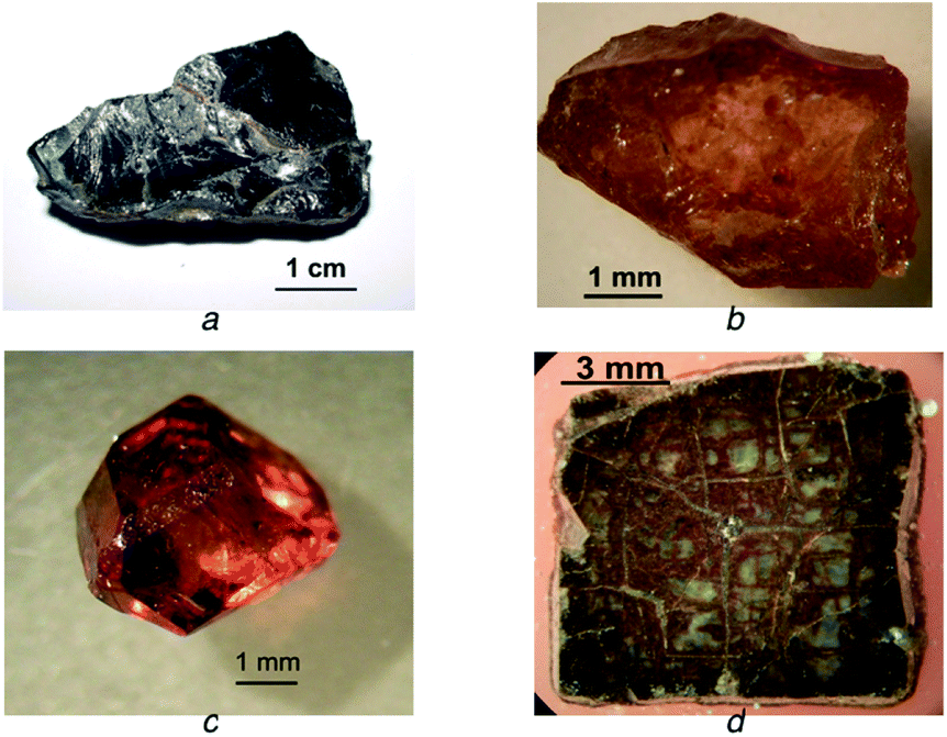 | ||
| Fig. 1 Pictures of the samples under study: a – metamict samarksite (Y–Fe-niobate); b – metamict rinkite; c – jacinth (a crystal of transparent zircon); d – cross-section of a metamict zircon crystal. | ||
| Sample | ZrO2 mass fraction, mass% | Element atomic concentration, % | |||
|---|---|---|---|---|---|
| U | Th | Pb | Gd | ||
| 1 | 100 | 0 | 0 | 0 | 0 |
| 2 | 98 | 0.9 | 1.1 | 0 | 0 |
| 3 | 94.8 | 2.6 | 2.6 | 1.9 | 1.9 |
| 4 | 80.2 | 9.5 | 6.5 | 1.9 | 1.9 |
 | ||
| Fig. 2 Pellet of powdered jacinth used for analysis. | ||
Acquired results were validated using ICP-OES after sample dissolution. Several methods were tested as unified sample dissolution approach: acid dissolution, fusion with potassium hydrogen sulphate, sodium tetraborate28 or mixture of sodium fluoride and potassium hydrogen fluoride.29 However, satisfactory results were obtained only for the last variant. Only for the pyrochlore specimen the dissolution was unsuccessful owing to precipitations. In brief, sample digestion was as follows: a highly dispersed sample (0.05 g) was gradually heated with 20 times excess of the mixture KHF2/NaF (3![[thin space (1/6-em)]](https://www.rsc.org/images/entities/char_2009.gif) :1) in a platinum crucible till the end of vapour emission and reaction mixture solidification; afterwards, the temperature was raised till the formation of fully transparent fusion (ca. 900 °C). Cooled fusion was treated with concentrated sulphuric acid (5 mL) heated until the appearance of vapours; 3 mL of nitric acid (1:9) was added and the mixture was quantitatively transferred to a volumetric flask (50 mL). For more detail on the dissolution procedure, please, see Singh et al.29
:1) in a platinum crucible till the end of vapour emission and reaction mixture solidification; afterwards, the temperature was raised till the formation of fully transparent fusion (ca. 900 °C). Cooled fusion was treated with concentrated sulphuric acid (5 mL) heated until the appearance of vapours; 3 mL of nitric acid (1:9) was added and the mixture was quantitatively transferred to a volumetric flask (50 mL). For more detail on the dissolution procedure, please, see Singh et al.29
Results and discussion
Method optimisation
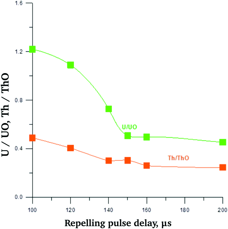
In preliminary experiments mass spectra of the metallic uranium and tablets of UO2 were compared. Experimental mass spectra for metallic uranium and UO2 are presented in the ESI Fig. S1a and S1b,† respectively. For the registration of both mass spectra high purity aluminium auxiliary cathode was used. The main difference is the presence of signals of 238U16O+ (m/z = 254) and 40Ar1H+ (m/z = 41) in the mass spectrum of UO2. At the same time, intensity of 238U+ for the metallic U and UO2 are comparable. That is related to high efficacy of UO2 sputtering due to formation of the surface conducting layer.22 The presence of oxide cluster 238U16O+ is caused by oxygen atomisation from the sample. Notably, relative oxygen concentration in the gaseous phase (O/U ratio) considerably exceeds that one in the solid sample as lifetime of oxygen atom in the discharge is much longer than that of uranium. The lifetime for oxygen is determined by argon flow rate and rates of ion molecular reactions (ca. 1–2 ms), whereas for uranium the lifetime is defined by its diffusion rate to the cell wall (0.2–0.3 ms). Since under the repulse delays used the intensity of O+ is negligible, the following reactions are the main source of UO+: Ar + e− → Ar*; Ar* + U → Ar + U+ + e−; U+ + O → UO+.The presence of oxide clusters certainly worsens the analytical figures of merit for the method, first of all, by causing additional interferences and deceasing precision as analyte is redistributed into several species. Thus, for real sample analysis the contribution of oxide clusters should be minimised. Noteworthy, really hampered analyte signal registration is occurring only for the elements forming very strong bonds with oxygen, such as actinides, rare earth elements and several other refractory metals, e.g. Ta, Nb and Zr (for more details, please, see ESI Fig. S2 and S3†). Relative intensities of oxide clusters can be, to some extent, controlled by optimising the duration of repelling pulse delay (τi) relatively to the discharge pulse time. In this case lower τi leads to decrease of dwelling time of the ion in the gaseous phase. Consequently, the probability for the reaction M+ + O → MO+ decreases, leading to lower intensities of oxide components in the mass spectrum. Fig. 3 shows the dependencies of intensity of U+ and intensity ratio U+ to UO+ on the delay time τi. Maximal U+ signal was observed for τi of 140–150 μs, at the same time, intensity ratio U+/UO+ monotonously decreased with raising τi. According to the results acquired, optimal τi lies in the range 120–160 μs. Nevertheless, even for this range for admixture determination total intensity of U+ + UO+ should not be disregarded. According to Ganeev et al.,25 usage of auxiliary cathode made of tantalum enabled to decrease water and oxygen content in the discharge cell due to getter side reactions: Ta + O → TaO → cell wall (1); Ta + H2O → TaOH2 → cell wall (2).
 | ||
| Fig. 3 Dependence of intensities ratio for U+ to UO+ on repelling pulse delay time τi for UO2 (aluminium auxiliary cathode). | ||
However, in case of oxide samples analysis the use of tantalum cathode was found to be ineffective as the rate of the oxygen scavenging reactions was too low to compensate oxygen supply from the solid sample to the gaseous phase. Relative intensities of oxide components (MO+) changed insignificantly and new interfering clusters, such as TaO+, TaO2+, TaAr+, TaArO+etc., appeared in the mass spectrum. That is why in further studies aluminium auxiliary cathode was used for sample sputtering, except the experiment with jacinth sample, which is discussed below. It is noteworthy that intensive oxide clusters of UO+ are registered in several other mass spectrometry techniques when analysing uranium oxides. In particular, it is a feature of direct current GDMS with secondary electrode.30
Notably, for the mass spectra of both model samples and minerals under study the relative intensities of oxides increased compared to UO+ in case of UO2 sputtering. That may be related to higher oxygen content of studied minerals. Examples are presented in ESI Fig. S4† (model sample 2) and S5 (metamict rinkite). The dependence of U+/UO+ ratio for model sample 2 on repelling pulse delay time (τi) is less pronounced than that of UO2 (Fig. 4). Optimal τi values can be deduced from Fig. 5, in which the dependencies of U+, UO+, Th+ and ThO+ on τi are presented. As one may see, optimal τi value was in the range 140–160 μs.
 | ||
| Fig. 4 Dependence of intensities ratio for U+ to UO+ and for Th+ to ThO+ on repelling pulse delay time τi. For model sample 2 (aluminium auxiliary cathode). | ||
 | ||
| Fig. 5 Dependence of U+, UO+, Th+ and ThO+ intensities on τi for model sample 2 (aluminium auxiliary cathode). | ||
Calibration
Model samples 1–4 (Table 2) were used throughout for calibration purposes. Dependencies of F × IU+UO/IZr+ZrO and F × ITh+ThO/IZr+ZrO on U and Th content in the sample have been determined (Fig. 6), where F = CZr/(CZr + CU + CTh), C – element concentration in a model sample. Adequate linearity has been achieved enabling the usage of total intensities (M+ + MO+) for quantification. Model sample 3 was used for assessing relative sensitivities for U, Th, Gd, Pb and Zr. The results are presented in Table 3. | ||
| Fig. 6 Dependencies of IU+UO/IZr+ZrO and ITh+ThO/IZr+ZrO on U and Th content for model samples (aluminium auxiliary cathode). | ||
Uranium and thorium quantification in the minerals

where, IUl and IUOl are U+ and UO+ intensities for analysed sample; IUm and IUOm are these for model sample; Im and Iadd are intensity for addition for model and analysed sample, respectively. Analogously, for Th, IThl and IThOl are Th+ and ThO+ for analysed sample; IThm and IThOm are these for model sample; Im and Iadd are intensity for addition for model and analysed sample; CX – addition mass concentration in the sample; RSFU/X, RSFTh/X – relative sensitivity factors for the addition (Gd, Pb) for U and Th, respectively.

For jacinth Zr was used as internal standard in addition to Pb and Gd, since ZrO2 content was close to 100% (CZr = 81%, according to ICP-OES). Lead content was 2.1%. Besides, standard additions method was also employed. Thorium and uranium oxides (1.5% U and Th) were introduced into jacinth sample. In this case, U and Th concentrations (per cent) were calculated as follows:


I Ug and IUOg – U+ and UO+ intensities for jacinth; IThg and IThOg – Th+ and ThO+ intensities for jacinth; IZrg and IZrOg – Zr+ and ZrO+ intensities for jacinth; RSFU/Zr, RSFTh/Zr – relative sensitivity factors to Zr for U and Th, respectively.
For the samarksite shard specimen Zr was also used as internal standard as the use of addition method was impossible for the monolith. The content of Zr was determined by ICP-OES and amounted 0.75%.
For powdered metamict zircon, pyrochlore, IAEA reference material and monolith samarskite shard only one sample was prepared from each specimen. For metamict rinkite two replicate samples were prepared and 5 samples of a specimen were analysed in case of jacinth. For the comparison of different methods of U and Th quantitative determination in the first two samples Zr was employed as an internal standard, whereas for the third specimen Pb was used for this purpose; finally, for samples 3 and 5 standard additions were implemented. For each sample 5 to 6 mass spectra were registered. Afterwards, mean data and relative RSD were calculated. Acquired data are presented in Table 4.
| Sample | Mass fraction, % | |
|---|---|---|
| Uranium | Thorium | |
| Pyrochlore | 0.32 ± 0.02 | 0.40 ± 0.02 |
|
||
| Metamict rinkite | ||
| Sample 1 | 0.065 ± 0.015 | 0.52 ± 0.005 |
| Sample 2 | 0.063 ± 0.015 | 0.50 ± 0.005 |
|
||
| Jacinth | ||
| ‘Standard’ mode: pulse duration of 3 μs, Al auxiliary cathode | ||
| Sample 1 (internal standard – Zr) | 0.040 ± 0.005 | 0.075 ± 0.005 |
| Sample 2 (internal standard – Zr) | 0.038 ± 0.005 | 0.061 ± 0.005 |
| Sample 3 (internal standard – Pb) | 0.044 ± 0.005 | 0.062 ± 0.005 |
| Sample 4 (standard additions method) | 0.047 ± 0.005 | 0.068 ± 0.005 |
| Sample 4 after sputtering with prolonged impulse duration of 4.5 μs, Ta auxiliary cathode | 0.045 ± 0.005 | 0.075 ± 0.005 |
| Sample 5 (addition method) without calcination in vacuum oven | 0.048 ± 0.005 | 0.083 ± 0.005 |
| After calcination in vacuum oven (1000 °C, 1 h), delay 180 μs | 0.072 ± 0.005 | 0.12 ± 0.005 |
Fig. 7 represents mass spectra ranges for aluminium cathode (Fig. 7a), tantalum cathode without (Fig. 7b) and after preliminary discharge treatment (Fig. 7c). As it may be concluded from the Fig. 7 preliminary discharge treatment considerably decreased ZrO+ intensity compared to that of Zr+. Analogously, for UO+/U+ and ThO+/Th+ similar tendencies were observed (Fig. 8). Fig. 8a presents the data for U and Th for aluminium cathode, whereas Fig. 8b is the same spectrum for preliminary treated sample. The observed effect could be explained by sample stoichiometry shift due to oxygen elimination from the sample by the forced discharge. In case of predominant discharge treatment the output of the process (1) is suitable for efficient oxygen removal from the gaseous phase, at least, for the oxygen, which appeared in the space of discharge during sample sputtering. As one may see from Table 4, measured concentration values of U and Th after the treatment were nearly the same as for the ‘standard’ mode. Nevertheless, relative intensities to zirconium for some elements, namely Pb, Sr and Ti, decreased several times. Thus, usage of such discharge treatment required further studies.
 | ||
| Fig. 7 Jacinth mass spectrum range with Zr+ and ZrO+ components obtained for aluminium cathode (a), tantalum cathode without discharge treatment (b) and tantalum auxiliary cathode after the treatment (c). | ||
 | ||
| Fig. 8 Jacinth mass spectrum range with uranium and thorium components obtained for aluminium cathode without discharge treatment (a) and after the treatment (b). | ||
Data validation
According to Table 1, measured uranium content in IAEA reference material met target value. The results obtained by the designed method and using ICP-OES, X-ray fluorescence spectrometry (EDX) and scanning electronic microscopy (EDX SEM) were mainly in concordance with each other. The results acquired by EDX and EDX SEM were quite close to those obtained by GDMS and ICP-OES in case of samarskite and pyrochlore. However significantly different results were obtained for metamict rinkite. Several factors may have contributed to the inconsistency observed. For EDX SEM and EDX heterogeneous distribution of U and Th in the sample surface is limiting the accuracy. As one may see from Table 1, for metamict zircon, rinkite and samarksite deviations of measured U and Th exceed tens of percent. Sample matrix also may significantly effect the calibration for both EDX and EDX SEM.Considerable difference in GDMS and ICP-OES results of uranium concentration in case of rinkite and zircon may be defined by the sample preparation prior to ICP-OES. Importantly, considerable inconsistency between the GDMS and ICP-OES results were present for U, whereas for Th the results were in agreement within experimental error. It may be related to uncontrolled U loss during fusion with fluorine containing reagents and consequent sample dissolution. Although for model samples no U volatilisation was observed, it might have occurred for metamict rinkite and especially metamict zircon samples, leading to U underestimation by ICP-OES. Unfortunately, fluoride free methods were inapplicable for our samples providing low dissolution efficacy. Additionally, for the rinkite sample U mass fraction was quite close to the ICP-OES limit of detection (ca. 0.02%).
Limits of detection
Limits of detection for the designed method were estimated using 3σ-criterion for the blank sample (sample 1, Table 2) and was found to be 0.3 ppm for uranium and 0.5 ppm for thorium. Limits of detection in our case were mainly confined by the number of dispersed ions with masses of 232, 238, 248 and 254.Isotope ratios determination
To estimate the possibility of performing direct isotope analysis without isotopic calibration 235U mean values and relative standard deviations were determined for the model sample and for the pyrochlore specimen. Isotope ratios for lead were estimated in jacinth with lead addition and in the zircon specimen. Relative concentration of lead isotope can alter drastically as all main lead isotopes 206Pb, 207Pb and 208Pb are of radiogenic origin being the final stage of radioactive decay of U and Th natural isotopes. The accuracy of 235U quantification is determined mainly by its content in the sample. For the model specimen (U concentration of 2.6%) accuracy of 235U determination was ca. 1.5% (measured relative content of 235U 0.73 ± 0.01%); however, for e.g. pyrochlore sample (U concentration of 0.32%) the error was about 6% (measured relative content of 235U 0.76 ± 0.05%). Noteworthy, acquired results for 235U are in concordance with its natural abundance (0.72%). Results for lead isotope ratios are presented in Table 5. The LA-ICP-MS data for 208Pb/206Pb and 207Pb/206Pb ratios in different glasses31 are also shown for comparison. According to the data presented in Table 5, for both Pb and U relative error steadily increased with concentration decrease. On the other hand, although the uncertainty was relatively high, isotope ratios for 208Pb/206Pb and 207Pb/206Pb measured in the current study matched the ranges previously published by Sjastad et al.31 Consequently, the absence of significant systematic error compared to random one could be assumed even without using specific isotope calibration. Isotope ratio determination accuracy seems to be defined mainly by statistical deviation for the number of detected ions. So optimisation of acquisition time may somewhat improve the accuracy.| Samples | 208Pb/206Pb | 207Pb/206Pb |
|---|---|---|
| Jacinth with added lead (2.2%) | 2.06 ± 0.01 | 0.841 ± 0.006 |
| Zircon (0.05%) | 2.04 ± 0.04 | 0.92 ± 0.02 |
| Literature data | (1.816–2.121) ± 0.001 | (0.777–0.901) ± 0.002 |
Rare earth elements assessment
Certainly, time-of-flight mass spectrometry with pulsed glow discharge may be used for the determination of elements other than U and Th in minerals. For instance, rare earth elements can also be quantified that is confirmed by the metamict rinkite mass spectrum (Fig. 9). The following rare earth elements were detected: La, Ce, Nd and Sm. Thus, the same analytical approach as for U and Th is applicable for the quantification of these. | ||
| Fig. 9 Metamict rinkite mass spectrum range with the peaks of rare earth elements. | ||
Conclusions
To the best of our knowledge, the current study is the first one to report GDMS (PGD-TOFMS) quantification of uranium and thorium in rocks and minerals. Pulsed discharge time-of-flight mass spectrometry with combined hollow cathode as a variant of analytical GDMS was shown to be applicable for direct and rapid uranium and thorium determination in diverse minerals with detection limits comparable to LA-ICP-MS. At the same time, PGD-TOFMS could be easier used outside stationary laboratories owing to relative compactness and lower discharge gas consuming (one 8 litre cylinder per 3–6 month). Satisfactory agreement between results acquired using RSF and standard addition method was obtained. Similar results were also acquired for PGD-TOFMS and ICP-OES. Some inconsistency between these methods for several samples (metamict rinkite, metamict zircon) may be related to uranium volatilisation in the form of fluorides during sample preparation. In principle, suggested method is applicable for elemental and isotopic analysis of any oxide powders with minimal sample preparation and it may be employed in different spheres of science and technology. Further insights seem to be required for this method, however, to fully understand the cause of some inconsistency with the results acquired by other techniques.Abbreviations
| GDMS | Glow discharge mass spectrometry |
| ICP | Inductively coupled plasma |
| ICP-OES | Inductively coupled plasma optical emission spectrometry |
| ICP-MS | Inductively coupled plasma mass spectrometry |
| LA-ICP-MS | Laser ablation inductively coupled plasma mass spectrometry |
| PGD | Pulsed glow discharge |
| RF GD | Radio frequency glow discharge |
| RF PGD | Pulsed radio frequency glow discharge |
| RSD | Relative standard deviation |
| RSF | Relative sensitivity factor |
| TOF-MS | Time-of-flight mass spectrometry |
| τ i | Repelling pulse delay |
Acknowledgements
Authors are grateful to Chemical Analysis and Materials Research Centre, St. Petersburg State University (St. Petersburg, Russia) for providing access to their facilities.Notes and references
- M. Betti, Microchem. J., 2000, 67, 363–373 CrossRef CAS.
- R. C. Ewing, B. C. Chakoumakos, G. R. Lumpkin, T. Murakami, R. B. Greegor and F. W. Lytle, Nucl. Instrum. Methods Phys. Res., Sect. B, 1988, 32, 487–497 CrossRef.
- B. E. Burakov, M. Ojovan and W. E. Lee, Crystalline materials for actinide immobilisation, Imperial College Press, London, 2011 Search PubMed.
- J. Zheng, K. Tagami, S. Homma-Takeda and W. Bu, J. Anal. At. Spectrom., 2013, 28, 1676 RSC.
- G. Jia and J. Jia, J. Environ. Radioact., 2012, 106, 98–119 CrossRef CAS PubMed.
- X. Hou and P. Roos, Anal. Chim. Acta, 2008, 608, 105–139 CrossRef CAS PubMed.
- Saidou, F. Bochud, J. P. Laedermann, M. G. Kwato Njock and P. Froidevaux, Appl. Radiat. Isot., 2008, 66, 215–222 CrossRef CAS PubMed.
- R. R. Greenberg, P. Bode and E. A. de Nadai Fernandes, Spectrochim. Acta, Part B, 2011, 66, 193–241 CrossRef CAS.
- A. El-Taher, Appl. Radiat. Isot., 2012, 70, 350–354 CrossRef CAS PubMed.
- F. El-Daoushy and F. Hernández, Analyst, 2002, 127, 981–989 RSC.
- N. D. de Castilhos, F. L. Melquiades, E. L. Thomaz and R. O. Bastos, Appl. Radiat. Isot., 2014, 95C, 63–71 Search PubMed.
- D. Gunther and B. Hattendorf, TrAC, Trends Anal. Chem., 2005, 24, 255–265 CrossRef.
- B. Fernandez, F. Claverie, C. Pecheyran and O. F. X. Donard, TrAC, Trends Anal. Chem., 2007, 26, 951–966 CrossRef CAS.
- A. Hubert, F. Claverie, C. Pecheyran and F. Pointurier, Spectrochim. Acta, Part B, 2014, 93, 52–60 CrossRef CAS.
- J. S. Becker, C. Pickhardt and H. J. Dietze, Int. J. Mass Spectrom., 2000, 202, 283–297 CrossRef CAS.
- Q. Xiaoming, H. Zengqian, K. Zaw, M. Xuanxue, X. Wenyi and X. Hongbo, Ore Geol. Rev., 2009, 36, 52–64 CrossRef.
- N. J. G. Pearce, W. T. Perkins, J. A. Westgate and S. C. Wade, Quaternary Int., 2011, 246, 57–81 CrossRef.
- C. Pickhardt, I. B. Brenner, J. S. Becker and H. J. Dietze, Fresenius' J. Anal. Chem., 2000, 368, 79–87 CrossRef CAS PubMed.
- S. M. Chernonozhkin and A. I. Saprykin, Analitika i kontrol', 2011, 15, 413–420 Search PubMed.
- D. C. Duckworth, C. M. Barshick, D. A. Bostick and D. H. Smith, Appl. Spectrosc., 1993, 47, 243–245 CrossRef CAS.
- M. Betti and L. Aldave de las Heras, Spectrochim. Acta, Part B, 2004, 59, 1359–1376 CrossRef.
- A. A. Ganeev, A. R. Gubal, K. N. Uskov and S. V. Potapov, Russ. Chem. Bull., 2012, 61, 752–767 CrossRef CAS.
- L. A. D. Heras, E. Hrnecek, O. Bildstein and M. Betti, J. Anal. At. Spectrom., 2002, 17, 1011–1014 RSC.
- R. Qian, S. J. Zhuo, Z. Wang and P. K. Robinson, J. Anal. At. Spectrom., 2013, 28, 1061–1067 RSC.
- A. A. Ganeev, A. R. Gubal, S. V. Potapov, S. E. Pogarev, S. E. Sholupov, K. N. Uskov and I. S. Ivanov, J. Anal. Chem., 2013, 68, 1205–1211 CrossRef CAS.
- A. A. Ganeev, A. R. Gubal, S. V. Potapov and R. V. Tyukal'tsev, J. Anal. Chem., 2009, 64, 696–704 CrossRef CAS.
- M. Voronov and A. Ganeev, Spectrochim. Acta, Part B, 2009, 64, 416–426 CrossRef.
- J. Dolezal, P. Povondra and Z. Sulcek, Decomposition Techniques in Inorganic Analysis, American Elsivier Publishing Co., New York, 1966 Search PubMed.
- A. K. Singh, V. Padmasubashini and L. Gopal, J. Radioanal. Nucl. Chem., 2011, 294, 19–25 CrossRef.
- L. Pajo, G. Tamborini, G. Rasmussen, K. Mayer and L. Koch, Spectrochim. Acta, Part B, 2001, 56, 541–549 CrossRef.
- K. E. Sjastad, T. Andersen and S. L. Simonsen, Spectrochim. Acta, Part B, 2013, 89, 84–92 CrossRef.
Footnote |
| † Electronic supplementary information (ESI) available: Additional mass spectra. See DOI: 10.1039/c5ra13312b |
| This journal is © The Royal Society of Chemistry 2015 |