Electrochemical-reduction-assisted assembly of ternary Ag nanoparticles/polyoxometalate/graphene nanohybrids and their activity in the electrocatalysis of oxygen reduction†
Rongji Liu‡
a,
Zhaowei Xian‡b,
Shuangshuang Zhangac,
Chunhua Chen*b,
Zhihua Yangb,
Hang Lid,
Wanquan Zhengd,
Guangjin Zhang*a and
Hongbin Cao*a
aKey Laboratory of Green Process and Engineering, Institute of Process Engineering, Chinese Academy of Sciences, 100190, Beijing, China. E-mail: zhanggj@ipe.ac.cn; hbcao@ipe.ac.cn
bKey Laboratory of Optoelectronic Chemical Materials and Devices of Ministry of Education, College of Chemical and Environmental Engineering, Jianghan University, 430056, Wuhan, China. E-mail: cch1003@163.com
cUniversity of Chinese Academy of Sciences, 100049, Beijing, China
dJianghan University Institute for Interdisciplinary Research, 430056, Wuhan, China
First published on 25th August 2015
Abstract
The green, facile, electrochemical-reduction-assisted assembly of ternary Ag nanoparticles (NPs)@polyoxometalate (POM)/reduced graphene oxide (rGO) is reported. The POM served as an electrocatalyst and bridging molecule. Characterization using transmission electron microscopy (TEM), X-ray photoelectron spectroscopy (XPS), X-ray diffraction (XRD), Raman and FT-IR spectroscopy analysis, etc., was performed and verified the structure of the prepared nanohybrids of Ag NPs@POM/rGO. The density and size of the Ag NPs on the rGO can be simply tuned by changing the concentration of Ag+. Most importantly, it is interesting to find that the ternary Ag NPs@POM/rGO nanohybrids showed much better electrocatalytic activities towards the oxygen reduction reaction than binary Ag NPs@POM and POM/rGO nanohybrids, and a direct four-electron transfer pathway was observed because of the synergistic effect of the Ag NPs and rGO. The electrocatalytic performance of Ag NPs@POM/rGO depended on the loading amount of Ag NPs, and 30% Ag NPs@POM/rGO showed the best electrocatalytic performance.
1. Introduction
The global energy crisis has stimulated more and more attention towards novel means of renewable energy storage and conversion by sustainable chemical methods. Catalysts of the oxygen reduction reaction (ORR) at the cathode play a vital role in renewable energy technologies, including fuel cells, and metal–air batteries.1–8 Among the catalysts used on cathodes, although platinum (Pt) is known to be a superior catalyst with high activity and stability, it is expensive and has a limited future supply. Fuel cells or metal–air batteries will realize commercial viability when the expensive Pt-based electrocatalysts are replaced by efficient, low-cost, and stable cathodes.3,9–13 In this context, tremendous effort has been made to reduce or replace Pt-based catalysts for the ORR;1–19 thus, many metal-free catalysts5,7,10,20–22 and Pt-free noble metals (e.g. silver (Ag), gold (Au) and palladium (Pd)) with much lower cost23–34 have been realized with comparable – or even better – catalytic effects than Pt for cathodic ORR in fuel cells. Among them, Ag nanostructure catalysts have been found to have comparable overpotentials and similar activities to Pt catalysts.27–34 Thus, development of Ag-based electrocatalysts has attracted more and more attention. In parallel, since its discovery by Novoselov et al.,35 graphene has received considerable attention in many fields, such as nanocomposites,36 fuel cells,30,32 solar cells,37,38 batteries,39 supercapacitors,40 etc., due to its large specific surface area, high chemical stability and excellent electronic and mechanical properties. Moreover, reduced graphene oxide (rGO) has been considered as an attractive support material for metal nanoparticle (NP) catalysts since its facile wet-chemical synthesis reported by Li et al.41 Thus, Ag NPs/rGO nanohybrid materials have received particular attention due to their high catalytic performance in the ORR.30,32,42 Although a large variety of conditions and protocols have been suggested for the synthesis of nanohybrids of metal NPs/rGO,43–45 it is still desirable to develop a green, mild and effective route that provides well-dispersed Ag NPs with good controllability and reproducibility without using hazardous reductants, e.g. hydrazine.Polyoxometalates (POMs) are early transition metal oxygen anionic inorganic clusters with high intrinsic electronic conductivity, ionic conductivity and protonic conductivity, which show promising applications in photo/electronic catalysis.46 POMs are considered as novel green agents in many wet-chemical processes due to their recyclability during the oxidation/reduction process. Recently, we developed a novel green method for decoration of various metal nano-objects (Au NPs, Ag NPs, Pt NPs, Pd NPs and Ag nanonets) on carbon nanotubes (CNTs) or rGO by using POMs as the sole agent.33,34,47–50 Herein, by using an electrochemical-reduction-assisted assembly method, this work provides novel ternary nanohybrids of Ag NPs@POM/rGO with several benefits. The prepared nanohybrids showed enhanced electrocatalytic activities toward the ORR via a direct four-electron process.
2. Experimental section
2.1 Reagents and materials
H3PW12O40 (PW12), AgNO3 and Nafion 117 solution (∼5% in a mixture of lower aliphatic alcohols and water) were purchased from Sigma-Aldrich. Pt/C catalyst (nominally 20% platinum on a high surface area advanced carbon support) was purchased from Alfa Aesar (Johnson Matthey Inc.). Isopropanol was purchased from Beijing Chemical Reagents Corporation (analytical grade) and was used as received. All other reagents were of analytical grade. Ultrapure water purified by a Milli-Q (MQ) plus system (Millipore Co.) with a resistivity of 18.2 MΩ cm was exclusively used in all aqueous solutions and rinsing procedures.2.2 Synthesis of nanohybrids of Ag NPs@POM/rGO
GO was oxidized from natural G flakes by a modified Hummers' method51 using H2SO4, NaNO3 and KMnO4 in an ice bath, as reported in great detail elsewhere.52 In a typical synthesis, an aqueous solution of PW12 (20 mL, 2.0 mM) was mixed with an aqueous solution of GO (1.52 mL, 1.0 mg mL−1) under the assistance of sonication and stirring to form a homogeneous suspension; pH = 1.0H2SO4 was used as the solvent. Controlled potential coulometry measurements were conducted in a three-electrode conventional glass cell with the mixed suspension of PW12 and GO as the electrolyte solution. A glassy carbon (GC) plate was used as the working electrode, a saturated calomel electrode (SCE) was used as the reference electrode and Pt gauze with high surface area was used as counter electrode. It should be noted that both the reference and counter electrodes were separated from the electrolyte by a glass frit. The electrolyte was saturated with ultrahigh-purity argon (Ar) for at least 30 min and kept under a positive pressure of this gas during experiments. To fully reduce the PW12 solution by 4 electrons, a potential of −0.4 V vs. the SCE was set on the working electrode. After the electrochemical reduction was completed, the blue-black solution of the reduced PW12/rGO hybrids was mixed with an aqueous solution of AgNO3 (120 μL, 50 mM) at room temperature by gentle shaking by hand. After several minutes of reaction, the ternary nanohybrids (30% Ag NPs@POM/rGO) were prepared. Similar X% Ag NPs@POM/rGO nanohybrids with different Ag NP loadings on rGO can be simply tuned by changing the concentration of Ag+ under otherwise identical conditions, where X% is the designated loading amount based on the following eqn (1):
 | (1) |
The samples were then centrifuged at 10![[thin space (1/6-em)]](https://www.rsc.org/images/entities/char_2009.gif) 000 rpm for 10 min and washed three times with pure water. Before further characterization, the nanocomposites were dried in a vacuum oven at 80 °C for 48 h. Ag NPs@POM and POM/rGO were prepared using the same method without adding GO or AgNO3, respectively.
000 rpm for 10 min and washed three times with pure water. Before further characterization, the nanocomposites were dried in a vacuum oven at 80 °C for 48 h. Ag NPs@POM and POM/rGO were prepared using the same method without adding GO or AgNO3, respectively.
2.3 Characterization
Transmission electron microscopy (TEM) images were obtained using a JEM-2010 transmission electron microscope at an acceleration voltage of 200 kV. X-ray photoelectron spectroscopy (XPS) measurements were performed in ultrahigh vacuum (UHV) with a Krato, AXIS-HS monochromatized Al Kα cathode source, at 75–150 W, using a low energy electron gun for charge neutralization. X-ray diffraction (XRD) studies were performed using a Bruker AXS D advance powder diffractometer with Cu Kα radiation (λ = 0.15418 nm). Raman spectra were obtained using a Renishaw Raman system model 1000 spectrometer. 532 nm radiation from a 20 mW air-cooled argon ion laser was used as the excitation source. The laser diameter was 1 μm, and the laser power at the sample position was 4.0 mW. The data acquisition time was 10 s. Fourier transform infrared (FT-IR) spectroscopy patterns were measured in the range 400–4000 cm−1 on an Alpha Centauri FTIR spectrophotometer.2.4 Electrochemistry experiments
5 mg of the finely ground catalyst (POM/rGO and Ag NPs@POM/rGO) was dispersed in 2.5 mL of anhydrous alcohol (2 mg mL−1) with at least 30 min sonication to form a homogeneous ink. Then, 38 μL of the catalyst ink was loaded onto a glassy carbon (GC) rotating disk electrode (RDE) or a rotating ring-disk electrode (RRDE) of 4 mm in diameter (the loading of catalysts was 0.6 mg cm−2). For preparation of Ag NPs@POM electrodes, the mother solution was centrifuged at 10![[thin space (1/6-em)]](https://www.rsc.org/images/entities/char_2009.gif) 000 rpm and about 430 μL of the black catalyst paste was left at the bottom of the centrifuge tube. Then, 5 μL of the prepared catalyst ink was dropped onto the GC electrode (the loading of catalysts was 0.06 mg cm−2). Because the metal loading in the catalysts was different, the amount of Ag NPs per square centimeter on the working electrode with Ag NPs@POM, 10, 20, and 30% Ag NPs@POM/rGO catalysts was 0.06, 0.06, 0.12, and 0.18 mg cm−2, respectively. It should be noted that only a very small amount of POM was present in the Ag NPs@POM hybrids. In order to fabricate the working electrode of the Pt/C catalyst, 1 mg of catalyst was dispersed in 1 mL of anhydrous alcohol (1 mg mL−1) by sonication for at least 30 min to form a homogeneous ink. Then 6.3 μL of catalyst ink was loaded onto a GC electrode of 4 mm in diameter (the loading of catalyst was 0.05 mg cm−2). After drying, all these electrodes were further modified by a thin film of Nafion by dropping 5.0 μL of 0.1 wt% Nafion solution onto the surface.
000 rpm and about 430 μL of the black catalyst paste was left at the bottom of the centrifuge tube. Then, 5 μL of the prepared catalyst ink was dropped onto the GC electrode (the loading of catalysts was 0.06 mg cm−2). Because the metal loading in the catalysts was different, the amount of Ag NPs per square centimeter on the working electrode with Ag NPs@POM, 10, 20, and 30% Ag NPs@POM/rGO catalysts was 0.06, 0.06, 0.12, and 0.18 mg cm−2, respectively. It should be noted that only a very small amount of POM was present in the Ag NPs@POM hybrids. In order to fabricate the working electrode of the Pt/C catalyst, 1 mg of catalyst was dispersed in 1 mL of anhydrous alcohol (1 mg mL−1) by sonication for at least 30 min to form a homogeneous ink. Then 6.3 μL of catalyst ink was loaded onto a GC electrode of 4 mm in diameter (the loading of catalyst was 0.05 mg cm−2). After drying, all these electrodes were further modified by a thin film of Nafion by dropping 5.0 μL of 0.1 wt% Nafion solution onto the surface.
Cyclic voltammetry (CV) and linear sweep voltammetry (LSV) measurements were performed on a CHI 760E electrochemical workstation (CHI Instrument, Inc.). A standard three-electrode cell was used and was controlled at 25 °C using a water bath during the experiment. A platinum foil (3.0 cm2) and Ag/AgCl were used as counter and reference electrodes, respectively. The prepared thin film GC RDE was used as the working electrode. The electrolyte, consisting of a solution of 0.1 M KOH, was saturated with ultrahigh-purity Ar for 30 min before CV measurements. Oxygen reduction experiments were performed by saturating with ultrahigh-purity O2 for 30 min before CV measurements. Steady state polarization measurements for the ORR were obtained using the RDE and rotating ring-disk electrode (RRDE) techniques. The Ag/AgCl was calibrated with respect to the reversible hydrogen electrode (RHE) in all measurements. In 0.1 M KOH, E(RHE) = E(Ag/AgCl) + 0.949 V.53
3. Results and discussion
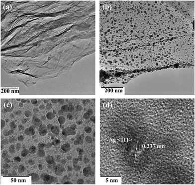
During synthesis, the POM worked as both electrocatalyst and bridging molecule. Scheme 1 shows the electrochemical-reduction-assisted assembly procedure of representative ternary Ag NPs@POM/rGO nanohybrids. The reduced POM (blue color), also called heteropoly blue (HPB), can be obtained conveniently through controlled potential bulk electrolysis at a glassy carbon working electrode. The blue color is generally attributed to d–d and intervalence charge transfer, W(V)/W(VI).54 HPB can easily transfer electrons to GO and reduce it to rGO, and it then reverts to the initial POM. When electrolysis occurs, the POM can be further reduced to HPB, and the HPB can be adsorbed on the surface of rGO; thus, HPB/rGO hybrids were formed in the solution. After that, Ag+ was added; HPB can easily transfer electrons to Ag+ and reduce it to Ag NPs; finally, Ag NPs@POM/rGO nanohybrids formed. The samples were centrifuged and washed with pure water before subsequent characterization. Fig. 1 shows typical TEM images of the pure rGO and Ag NPs@POM/rGO nanohybrids. Fig. 1a displays the as-prepared rGO as a crumpled nanosheet, which was formed by the superposition of several layers. Typical TEM images of 30% Ag NPs@POM/rGO (Fig. 1b and c with different magnifications) show that Ag NPs with an average diameter of 15 ± 3 nm (determined from a statistical study of 50 NPs) were uniformly dispersed on the surface of rGO. We have reported previously that metal NPs@POM can easily form a core–shell structure due to their strong interaction,34,47–50 and POM clusters can be easily adsorbed on rGO.33,47,48,52,55 Thus, the POMs worked as bridging molecules to facilitate the binding of Ag NPs to rGO. Electrostatic repulsion between the negatively charged POMs prevents the Ag NPs from aggregating. The Ag NPs showed a highly monocrystalline character, which is proved by the HRTEM image shown in Fig. 1d. The lattice fringe of the Ag (111) crystalline face (0.237 nm) can be observed in the figure. In situ energy dispersive X-ray (EDX) analysis (Fig. S1, ESI†) shows that strong tungsten peaks exist as well as the Ag peaks, confirming the existence of the POM around the Ag NPs/rGO. The strong peaks of Cu are from the copper grid. | ||
| Scheme 1 Electrochemical-reduction-assisted assembly procedure of the representative ternary Ag NPs@POM/rGO nanohybrids. | ||
The nanohybrid was further characterized by XRD, XPS, Raman and FT-IR spectra. XRD patterns of pure PW12, GO and 30% Ag NPs@POM/rGO are displayed in Fig. 2. It can be observed that a feature diffraction peak of GO appeared at 11.2°, corresponding to a C (002) interlayer spacing of 0.790 nm.56 After exfoliation of GO by POM-assisted photoreduction, the peak at 11.2° disappeared and a new composite characteristic peak emerged at about 26.6° that represents the C (002) of rGO, meaning that the as-prepared rGO contained several layers, which is in agreement with the TEM results. In addition, other peaks for PW12 and Ag (the observed characteristic peaks at 38.4°, 44.6° and 64.6° are assigned to the (111), (200) and (220) Bragg reflections of Ag crystals of face-centered cubic (fcc) structure)33,34 were also observed in the Ag NPs@POM/rGO nanohybrids, which confirmed the formation of ternary hybrids of Ag NPs@POM/rGO.
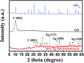 | ||
| Fig. 2 XRD spectra of PW12, GO and the as-prepared 30% Ag NPs@POM/rGO. * represents the characteristic peaks for PW12. | ||
XPS was used to further verify the as synthesised nanohybrids. Fig. 3a and b show the C 1s XPS spectra of GO and 30% Ag NPs@POM/rGO. Four types of carbon with different chemical states are observed for GO (Fig. 3a), which appear at 284.8 eV for graphite-like C, 287.0 eV for C–O, 288.0 eV for C![[double bond, length as m-dash]](https://www.rsc.org/images/entities/char_e001.gif) O and 289.0 eV for O–C
O and 289.0 eV for O–C![[double bond, length as m-dash]](https://www.rsc.org/images/entities/char_e001.gif) O, respectively.52,55 For Ag NPs@POM/rGO (Fig. 3b), the content of C–O groups (286.5 eV) decreases from an initial value of 31.1–8.6% (Table 1), which indicates that photoreduction can effectively eliminate the oxygen-containing groups on GO. Meanwhile, the content of C–C/C
O, respectively.52,55 For Ag NPs@POM/rGO (Fig. 3b), the content of C–O groups (286.5 eV) decreases from an initial value of 31.1–8.6% (Table 1), which indicates that photoreduction can effectively eliminate the oxygen-containing groups on GO. Meanwhile, the content of C–C/C![[double bond, length as m-dash]](https://www.rsc.org/images/entities/char_e001.gif) C groups for Ag NPs@POM/rGO increased from initially 59.4% of GO to 82.7%, indicating that a significant amount of graphite-like carbon structures was restored.
C groups for Ag NPs@POM/rGO increased from initially 59.4% of GO to 82.7%, indicating that a significant amount of graphite-like carbon structures was restored.
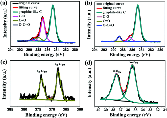 | ||
| Fig. 3 C 1s XPS spectra of (a) GO and (b) as-prepared 30% Ag NPs@POM/rGO; XPS spectra of Ag 3d (c) and W 4f (d) in the as-prepared nanohybrids. | ||
| Samples | Graphite-like C | C–O | C![[double bond, length as m-dash]](https://www.rsc.org/images/entities/char_e001.gif) O O |
O–C![[double bond, length as m-dash]](https://www.rsc.org/images/entities/char_e001.gif) O O |
|---|---|---|---|---|
| GO | 284.8 (59.4%) | 287.0 (31.1%) | 288.0 (7.5%) | 289.0 (2.0%) |
| 30% Ag NPs@POM/rGO | 284.8 (82.7%) | 286.5 (8.6%) | 287.5 (0) | 288.8 (8.7%) |
The oxidation state of the silver nanoparticle structures attached to rGO and the presence of tungsten were also determined by XPS, as shown in Fig. 3c and d. The Ag 3d3/2 and 3d5/2 doublet can be easily observed in the XPS spectrum of the as-prepared Ag NPs@POM/rGO nanohybrids (Fig. 3c). With the charge effect corrected by fixing the photoelectric peak 1s of carbon at 284.8 eV, the 3d5/2 level is located at 368.2 ± 0.3 eV and that of 3d3/2 at 374.2 ± 0.3 eV.33,34 These values suggest unambiguously that silver is present only in the metallic form, indicating the formation of Ag NPs on the surface of rGO. The presence of tungsten was also detected, and the W4f7/2 and W4f5/2 doublet with binding energies of 35.41 and 37.58 eV, respectively, is shown in Fig. 3d.47–50 These values indicate that the tungsten is in its fully oxidized form (WVI) in the POM.
Raman spectroscopy is a useful technique for the elaboration of information about the structural properties of carbonaceous materials, including disorder and defect structures. For comparison, the Raman spectra of pure PW12, GO and the as-prepared 30% Ag NPs@POM/rGO were recorded (Fig. 4). In general, two fundamental vibrations which are attributed to the G (∼1600 cm−1) and D (∼1350 cm−1) bands, respectively, are observed for GO and 30% Ag NPs@POM/rGO. It is known that the G band corresponds to the first-order scattering of the E2g mode from the sp2 carbon domains and the D band is a breathing mode of k-point photons of A1g symmetry originating from the disorder-induced mode associated with structural defects and imperfections.47 The intensity ratio of D and G bands, ID/IG, is a measure of the disorder degree and the average size of the sp2 domains. It is worth noting that the ID/IG of Ag NPs@POM/rGO decreased from an initial 0.97 for GO to 0.88, which indicates that the reduction of GO indeed increased the average size of the crystalline graphene domains due to the graphitic ‘‘self-healing’’ in the hybrids.47 In addition, Raman signals of the vas(W–Ob–W), vas(P–Oa) and vas(W![[double bond, length as m-dash]](https://www.rsc.org/images/entities/char_e001.gif) Od) bands of PW12 (from ∼830 to 1050 cm−1) were also detected in the Ag NPs@POM/rGO hybrids.
Od) bands of PW12 (from ∼830 to 1050 cm−1) were also detected in the Ag NPs@POM/rGO hybrids.
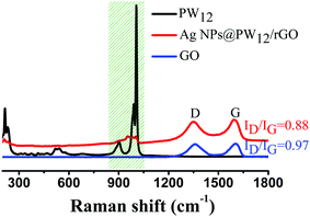 | ||
Fig. 4 Raman spectra of PW12, GO and the as-prepared 30% Ag NPs@POM/rGO. The shaded region from ∼830 to 1050 cm−1 includes the signals of the vas(W–Ob–W), vas(P–Oa) and vas(W![[double bond, length as m-dash]](https://www.rsc.org/images/entities/char_e001.gif) Od) bands of PW12. Od) bands of PW12. | ||
FT-IR spectra were recorded to verify the formation of hydrogen bonds. As shown in Fig. S2, ESI,† for free PW12, Keggin ion bands were observed at 1080 cm−1 for vas(P–O), 987 cm−1 for vas(W![[double bond, length as m-dash]](https://www.rsc.org/images/entities/char_e001.gif) O) terminal groups, 890 cm−1 for vas(W–O) corner sharing bonds and 811 cm−1 for vas(W–O) edge sharing bonds.49 In the Ag NPs@POM/rGO nanohybrids, the corresponding bands were identified at 1080 cm−1 for vas(P–O), 986 cm−1 for vas(W
O) terminal groups, 890 cm−1 for vas(W–O) corner sharing bonds and 811 cm−1 for vas(W–O) edge sharing bonds.49 In the Ag NPs@POM/rGO nanohybrids, the corresponding bands were identified at 1080 cm−1 for vas(P–O), 986 cm−1 for vas(W![[double bond, length as m-dash]](https://www.rsc.org/images/entities/char_e001.gif) O) terminal groups, 888 cm−1 for vas(W–O) corner sharing bonds and 809 cm−1 for vas(W–O) edge sharing bonds. It can be concluded that the W–O stretching bands are all red shifted by several wavenumbers. This indicates that hydrogen bonds are formed between the oxygen atoms of POM ions and the hydroxyl groups on carboxylic headgroups. Thus, POMs serve as bridging molecules between Ag NPs and rGO.
O) terminal groups, 888 cm−1 for vas(W–O) corner sharing bonds and 809 cm−1 for vas(W–O) edge sharing bonds. It can be concluded that the W–O stretching bands are all red shifted by several wavenumbers. This indicates that hydrogen bonds are formed between the oxygen atoms of POM ions and the hydroxyl groups on carboxylic headgroups. Thus, POMs serve as bridging molecules between Ag NPs and rGO.
It should be noted that the density and size of the Ag NPs on rGO can be simply tuned by changing the concentration of Ag+ under otherwise identical conditions. For example, when a lower amount of AgNO3 (70 μL or 30 μL) was added into the solution after photoreduction, the density and size of the Ag NPs on the surface of rGO can substantially be decreased, and thus the Ag loading changed to be about 20 or 10 wt%, respectively. Typical TEM images of the sample with these Ag NPs loadings are shown in Fig. S3, ESI.†
In the field of fuel cells and metal–air batteries, the ORR is an important reaction, and was selected as a preliminary test of the electrocatalytic behavior of the prepared nanohybrids. The reduction of O2 in alkaline electrolytes can proceed by the following two pathways,57 namely:
(1) Direct O2 reduction to OH− ions, what is called a four-electron pathway (2):
| O2 + 2H2O + 4e− → 4OH− | (2) |
(2) Oxygen reduction to HO2− ions, what is called a two-electron pathway (3):
| O2 + H2O + 2e− → HO2− + OH− | (3) |
| HO2− + H2O + 2e− → 3OH− | (4) |
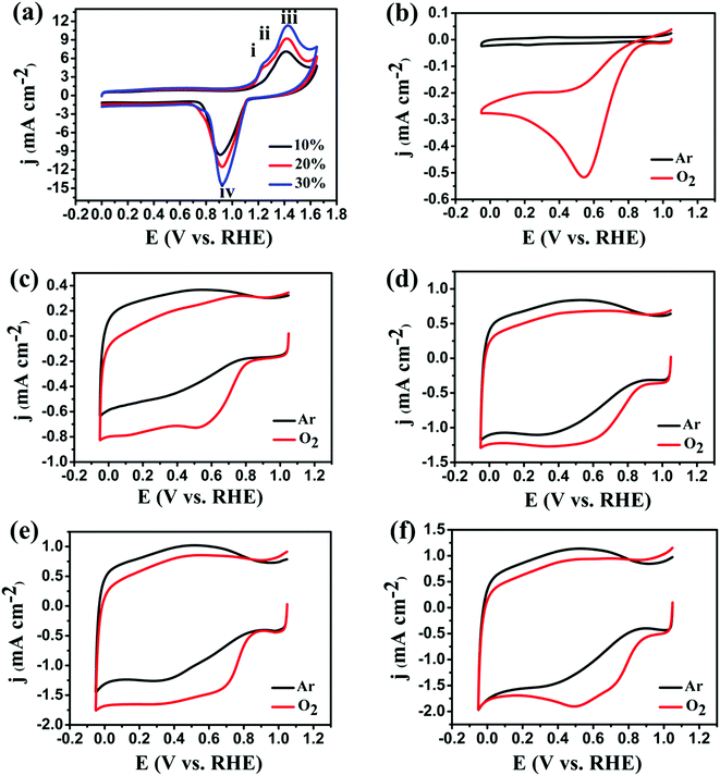
Fig. 5a shows representative CVs of 10%, 20% and 30% Ag NPs@POM/rGO nanohybrids in 0.1 M KOH that was saturated with Ar at a potential sweep rate of 50 mV s−1. In the potential range from +1.0 to +1.6 V vs. RHE, there are three anodic peaks observed and designated as i, ii, and iii, which are located at about 1.23, 1.30, and 1.41 V vs. RHE, respectively. Peak i is due to silver dissolution and the formation of a surface monolayer of Ag2O films, while peaks ii and iii are associated with the formation of bulk phases of AgOH and Ag2O. In the reverse potential scan, the cathodic current peak at +0.93 V vs. RHE (peak iv) is ascribed to the electroreduction of the silver oxides formed during the anodic potential scan.29,32,58 It is clearly shown that the peak intensities of i, ii, iii and iv are congruously increased with the increase of the Ag loading.
Fig. 5b–f show the cyclic voltammograms of the Ag NPs@POM, POM/rGO, 10% Ag NPs@POM/rGO, 20% Ag NPs@POM/rGO and 30% Ag NPs@POM/rGO modified GC RDEs in 0.1 M KOH solution, which were saturated with Ar or O2 during the experiments. Compared with the experiments performed in the Ar-saturated 0.1 M KOH solution, it is clearly shown that all catalysts exhibit catalytic activities toward the ORR when O2 exists in the electrolyte. The main characteristics determined from the CV patterns include the potential of the cathodic peak current (Epc) and the cathodic peak current density (ipc) (see Table S1, ESI†). For the Ag NPs@POM (Fig. 5b) and POM/rGO (Fig. 5c) modified electrodes, the Epc appeared at around +0.55 and +0.53 V vs. RHE, respectively. However, for the 10% Ag NPs@POM/rGO (Fig. 5d), 20% Ag NPs@POM/rGO (Fig. 5e) and 30% Ag NPs@POM/rGO (Fig. 5f) modified electrodes, the Epc shifted positively to +0.60, +0.71 and +0.74 V vs. RHE. Moreover, the ORR peak current increased gradually with the increase of the Ag loading. In comparison with the Ag NPs@POM and POM/rGO modified electrodes, higher current density and more positive Epc were obtained with the Ag NPs@POM/rGO nanohybrids. Such voltammetric characterization indicates that the nanohybrids showed much better electrocatalytic activities than Ag NPs@POM and POM/rGO. The better performance of the ternary nanohybrids is mainly due to the following two factors: (1) the highly conductive rGO will improve the charge transfer between the modifying layer and the GC substrate; (2) the synergistic effect of the Ag NPs and rGO is beneficial to their electrocatalytic activities.
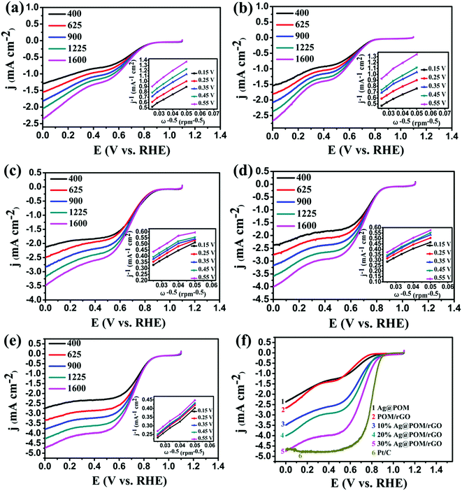
The RDE is an advanced technique for the study of the kinetics of the ORR. Fig. 6a–e show the LSV curves of the ORR at various rotation rates at Ag NPs@POM, POM/rGO, 10% Ag NPs@POM/rGO, 20% Ag NPs@POM/rGO and 30% Ag NPs@POM/rGO modified electrodes in an O2-saturated 0.1 M KOH solution at a scan rate of 10 mV s−1. Compared with Ag NPs@POM and POM/rGO, which exhibited onset potentials (Eonset, which is defined as the potential at which the ORR current is 5% of that measured at 0.3 V vs. RHE)59 of about +0.84 and +0.80 V vs. RHE, respectively, the Eonset of 10, 20 and 30% Ag NPs@POM/rGO shifted positively to about 0.88, 0.86 and 0.88 V vs. RHE, respectively. The enhanced catalytic performance of Ag NPs@POM/rGO can be attributed to the synergistic effect of Ag NPs and rGO. Koutecky–Levich plots for the five electrode materials at various potentials are shown in the insets. The transferred electron number per oxygen molecule involved in the oxygen reduction at each of the electrodes was determined by the Koutecky–Levich eqn (5):20,60
 | (5) |
| B = 0.2nF(DO2)2/3ν−1/6CO2 | (6) |
![[thin space (1/6-em)]](https://www.rsc.org/images/entities/char_2009.gif) 485 C mol−1), DO2 is the diffusion coefficient of O2 in 0.1 M KOH (1.9 × 10⁻⁵ cm2 s−1), v is the kinetic viscosity (0.01 cm2 s−1), and CO2 is the bulk concentration of O2 (1.2 × 10⁻⁶ mol cm−3). The constant 0.2 is adopted when the rotation speed is expressed in rpm. The numbers of electrons transferred for the ORR on the five electrodes calculated from the slopes of the Koutecky–Levich plots (shown in the insets of Fig. 6a–e) at various potentials are shown in Table S2 (see ESI†). It is interesting to find that the current densities of Ag NPs@POM/rGO increased gradually and Eonset shifted positively with the increase of the Ag loading (from 10% to 30%), and the transferred electron numbers of the Ag NPs@POM/rGO nanohybrids were higher than those of Ag NPs@POM and POM/rGO, regardless of the Ag loading. This shows that the oxygen reduction on Ag NPs@POM/rGO mainly proceeds by a pathway of four-electron transfer. This indicates that the Ag NPs@POM/rGO nanohybrids, which have a synergistic effect of Ag NPs and rGO, showed higher catalytic activities than Ag NPs@POM and POM/rGO. Thus we unambiguously conclude that Ag NPs@POM/rGO has high potential to be used as an electrocatalyst in the ORR. Furthermore, we also prepared 40% Ag NPs@POM/rGO nanohybrids and the electrochemical performance was examined. The LSV curves of the ORR in O2-saturated 0.1 M KOH solutions at the 30% Ag NPs@POM/rGO and 40% Ag NPs@POM/rGO electrodes are compared in Fig. S4, ESI.† It should be noted that these two catalysts show almost the same catalytic activities toward the ORR. This indicates that the optimal proportion of Ag NPs on the rGO is 30%; higher loadings of Ag NPs cannot further increase the catalytic activity, which may be attributed to the large particle size (about 22 ± 3 nm) and poor dispersibility of the Ag NPs (see typical TEM image for 40% Ag NPs@POM/rGO in Fig. S5, ESI†).
485 C mol−1), DO2 is the diffusion coefficient of O2 in 0.1 M KOH (1.9 × 10⁻⁵ cm2 s−1), v is the kinetic viscosity (0.01 cm2 s−1), and CO2 is the bulk concentration of O2 (1.2 × 10⁻⁶ mol cm−3). The constant 0.2 is adopted when the rotation speed is expressed in rpm. The numbers of electrons transferred for the ORR on the five electrodes calculated from the slopes of the Koutecky–Levich plots (shown in the insets of Fig. 6a–e) at various potentials are shown in Table S2 (see ESI†). It is interesting to find that the current densities of Ag NPs@POM/rGO increased gradually and Eonset shifted positively with the increase of the Ag loading (from 10% to 30%), and the transferred electron numbers of the Ag NPs@POM/rGO nanohybrids were higher than those of Ag NPs@POM and POM/rGO, regardless of the Ag loading. This shows that the oxygen reduction on Ag NPs@POM/rGO mainly proceeds by a pathway of four-electron transfer. This indicates that the Ag NPs@POM/rGO nanohybrids, which have a synergistic effect of Ag NPs and rGO, showed higher catalytic activities than Ag NPs@POM and POM/rGO. Thus we unambiguously conclude that Ag NPs@POM/rGO has high potential to be used as an electrocatalyst in the ORR. Furthermore, we also prepared 40% Ag NPs@POM/rGO nanohybrids and the electrochemical performance was examined. The LSV curves of the ORR in O2-saturated 0.1 M KOH solutions at the 30% Ag NPs@POM/rGO and 40% Ag NPs@POM/rGO electrodes are compared in Fig. S4, ESI.† It should be noted that these two catalysts show almost the same catalytic activities toward the ORR. This indicates that the optimal proportion of Ag NPs on the rGO is 30%; higher loadings of Ag NPs cannot further increase the catalytic activity, which may be attributed to the large particle size (about 22 ± 3 nm) and poor dispersibility of the Ag NPs (see typical TEM image for 40% Ag NPs@POM/rGO in Fig. S5, ESI†).
For comparison, we carried out LSV measurements on an RDE for each of the electrode materials (Ag NPs@POM, POM/rGO, 10% Ag NPs@POM/rGO, 20% Ag NPs@POM/rGO, 30% Ag NPs@POM/rGO and 20% Pt/C) in O2-saturated 0.1 M KOH at a scan rate of 10 mV s−1 and a rotation rate of 1600 rpm. The results show that the limiting current density of 30% Ag NPs@POM/rGO reaches the highest value of about −4.8 mA cm−2 at 0 V vs. RHE amongst the five electrodes, and is comparable to the commercial Pt/C catalyst with 20% loading, although it still has a more negative half-wave potential E1/2 (by ca. 100 mV, see Fig. 6f). It should be noted that the Ag loading mass of Ag NPs@POM was almost the same as that of 10% Ag NPs@POM/rGO (0.06 mg cm−2), but with much lower catalytic activity. This indicates that the Ag NPs@POM/rGO catalysts undergo the ORR via a four-electron transfer pathway due to the synergistic effect of the Ag NPs and rGO. Fig. S6, ESI† shows the LSV curves of the Ag NPs@POM/rGO catalysts in terms of mass activity (catalyst loading), which again confirms the higher catalytic activity of 30% Ag NPs@POM/rGO in comparison to 10 and 20 wt% Ag loading.
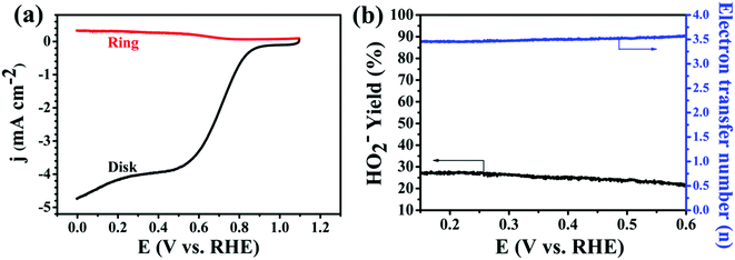
In addition, the RRDE is a useful technique for monitoring the formation of intermediate peroxide species (HO2−) during the ORR process. We thus performed the RRDE experiment for 30% Ag NPs@POM/rGO (Fig. 7a) with the same catalyst loading as that of the RDE test since the peroxide pathway is known to depend on the catalyst loading amount. The % HO2− and electron transfer number (n) were calculated from the ratio of the ring current (Ir) and the disk current (Id) following eqn (7) and (8):9
 | (7) |
 | (8) |
Since durability is another important issue for the ORR, the stability of the prepared nanohybrids was tested at a constant voltage of +0.7 V vs. RHE for 20![[thin space (1/6-em)]](https://www.rsc.org/images/entities/char_2009.gif) 000 s in a 0.1 M KOH solution saturated with O2 (Fig. 8). It should be noted that the corresponding current–time (i–t) chronoamperometric response of the 30% Ag NPs@POM/rGO modified electrode exhibited a relatively slower attenuation than commercial Pt/C (85% versus 65% still persisted after 20
000 s in a 0.1 M KOH solution saturated with O2 (Fig. 8). It should be noted that the corresponding current–time (i–t) chronoamperometric response of the 30% Ag NPs@POM/rGO modified electrode exhibited a relatively slower attenuation than commercial Pt/C (85% versus 65% still persisted after 20![[thin space (1/6-em)]](https://www.rsc.org/images/entities/char_2009.gif) 000 s), which indicates that the durability of the Ag NPs@POM/rGO nanohybrids is superior to that of the Pt/C catalyst. In addition, as a standard method, an accelerated degradation test (ADT) was performed to assess the stability of 30% Ag NPs@POM/rGO by cycling the catalyst between +0.1 and +1.1 V vs. RHE at 200 mV s−1 in an O2-saturated 0.1 M KOH solution.61 It indicates that the 30% Ag NPs@POM/rGO electrode showed a very small negative shift (∼10 mV) in E1/2 after 2000 continuous cycles (Fig. S7, ESI†), thus exhibiting excellent long-term operational stability.
000 s), which indicates that the durability of the Ag NPs@POM/rGO nanohybrids is superior to that of the Pt/C catalyst. In addition, as a standard method, an accelerated degradation test (ADT) was performed to assess the stability of 30% Ag NPs@POM/rGO by cycling the catalyst between +0.1 and +1.1 V vs. RHE at 200 mV s−1 in an O2-saturated 0.1 M KOH solution.61 It indicates that the 30% Ag NPs@POM/rGO electrode showed a very small negative shift (∼10 mV) in E1/2 after 2000 continuous cycles (Fig. S7, ESI†), thus exhibiting excellent long-term operational stability.
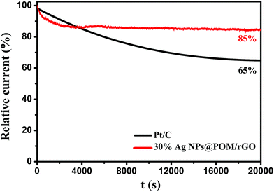 | ||
| Fig. 8 Current–time (i–t) chronoamperometric response of 30% Ag NPs@POM/rGO and Pt/C modified GC RDE at +0.70 V vs. RHE in O2-saturated 0.1 M KOH. | ||
4. Conclusion
In summary, novel ternary Ag NPs@POM/rGO nanohybrids were prepared by a green and facile electrochemical-reduction-assisted assembly method, in which the POM served as both electrocatalyst and bridging molecule. The Ag NPs@POM/rGO nanohybrids showed high electrocatalytic activity towards ORR via a direct four-electron process due to the synergistic effects of Ag NPs and rGO. Our results proved that the hybrids in our paper were sufficiently competitive with commercial Pt/C.Acknowledgements
This work was supported by the National Natural Science Foundation of China (No. 21371173, 51402298), the China Postdoctoral Foundation (No. 2014M550846) and the Wuhan Planning Project of Science and Technology (No. 2013011001010480).References
- K. Strickland, E. Miner, Q. Jia, U. Tylus, N. Ramaswamy, W. Liang, M. Sougrati, F. Jaouen and S. Mukerjee, Nat. Commun., 2015, 6, 7343 CrossRef CAS PubMed
.
- W. Yang, X. Liu, X. Yue, J. Jia and S. Guo, J. Am. Chem. Soc., 2015, 137, 1436–1439 CrossRef CAS PubMed
.
- X. Huang, Z. Zhao, L. Cao, Y. Chen, E. Zhu, Z. Lin, M. Li, A. Yan, A. Zettl, Y. M. Wang, X. Duan, T. Mueller and Y. Huang, Science, 2015, 348, 1230 CrossRef CAS PubMed
.
- Y. Meng, D. Voiry, A. Goswami, X. Zou, X. Huang, M. Chhowalla, Z. Liu and T. Asefa, J. Am. Chem. Soc., 2014, 136, 13554–13557 CrossRef CAS PubMed
.
- L. Dai, Y. Xue, L. Qu, H. Choi and J. Baek, Chem. Rev., 2015, 115, 4823 CrossRef CAS PubMed
.
- R. Silva, D. Voiry, M. Chhowalla and T. Asefa, J. Am. Chem. Soc., 2013, 135, 7823–7826 CrossRef CAS PubMed
.
- J. Zhang, Z. Zhao, Z. Xia and L. Dai, Nat. Nanotechnol., 2015, 10, 444 CrossRef CAS PubMed
.
- M. Lefèvre, E. Proietti, F. Jaouen and J.-P. Dodelet, Science, 2009, 324, 71–74 CrossRef PubMed
.
- Y. Liang, Y. Li, H. Wang, J. Zhou, J. Wang, T. Regier and H. Dai, Nat. Mater., 2011, 10, 780–786 CrossRef CAS PubMed
.
- K. Gong, F. Du, Z. Xia, M. Dustock and L. Dai, Science, 2009, 323, 760 CrossRef CAS PubMed
.
- N. R. Sahraie, J. P. Paraknowitsch, C. Göbel, A. Thomas and P. Strasser, J. Am. Chem. Soc., 2014, 136, 14486–14497 CrossRef PubMed
.
- L. Zhang, J. Zhang, D. P. Wilkinson and H. Wang, J. Power Sources, 2006, 156, 171 CrossRef CAS PubMed
.
- G. Tian, Q. Zhang, B. Zhang, Yu. Jin, J. Huang, D. Su and F. Wei, Adv. Funct. Mater., 2014, 24, 5956–5961 CrossRef CAS PubMed
.
- X. Wang, C. Ouyang, S. Dou, D. Liu and S. Wang, RSC Adv., 2015, 5, 41901 RSC
.
- C. You, S. Liao, H. Li, S. Hou, H. Peng, X. Zeng, F. Liu, R. Zheng, Z. Fu and Y. Li, Carbon, 2014, 69, 294–301 CrossRef CAS PubMed
.
- D. Ye, T. Wu, H. Cao, Y. Wang, B. Liu, S. Zhang and J. Kong, RSC Adv., 2015, 5, 26710 RSC
.
- J. S. Lee, G. S. Park, S. T. Kim, M. L. Liu and J. Cho, Angew. Chem., Int. Ed., 2013, 52, 1026–1030 CrossRef CAS PubMed
.
- R. Li, Z. Wei, X. Gou and W. Xu, RSC Adv., 2013, 3, 9978 RSC
.
- Y. Zheng, Y. Jiao, L. Ge, M. Jaroniec and S. Qiao, Angew. Chem., Int. Ed., 2013, 52, 3110–3116 CrossRef CAS PubMed
.
- Z. Ma, S. Dou, A. Shen, L. Tao, L. Dai and S. Wang, Angew. Chem., Int. Ed., 2015, 54, 1888 CrossRef CAS PubMed
.
- S. Wang, D. Yu and L. Dai, J. Am. Chem. Soc., 2011, 133, 5182–5185 CrossRef CAS PubMed
.
- L. Qu, Y. Liu, J. Baek and L. Dai, ACS Nano, 2010, 4, 1321–1326 CrossRef CAS PubMed
.
- M. Govindhan and A. Chen, J. Power Sources, 2015, 274, 928–936 CrossRef CAS PubMed
.
- M. Shao, T. Huang, P. Liu, J. Zhang, K. Sasaki, M. B. Vukmirovic and R. R. Adzic, Langmuir, 2006, 22, 10409 CrossRef CAS PubMed
.
- L. Xiao, L. Zhuang, Y. Liu, J. Lu and H. D. Abruña, J. Am. Chem. Soc., 2009, 131, 602–608 CrossRef CAS PubMed
.
- H. Yin, H. Tang, D. Wang, Y. Gao and Z. Tang, ACS Nano, 2012, 6, 8288–8297 CrossRef CAS PubMed
.
- Q. Yi, H. Chu, M. Tang, Z. Yang, Q. Chen and X. Liu, J. Electroanal. Chem., 2015, 739, 178–186 CrossRef CAS PubMed
.
- L. Pu, K. Li, Z. Chen, P. Zhang, X. Zhang and Z. Fu, J. Power Sources, 2014, 268, 476–481 CrossRef CAS PubMed
.
- Q. Wang, X. Cui, W. Guan, L. Zhang, X. Fan, Z. Shi and W. Zheng, J. Power Sources, 2014, 269, 152–157 CrossRef CAS PubMed
.
- S. Jin, M. Chen, H. Dong, B. He, H. Lu, L. Su, W. Dai, Q. Zhang and X. Zhang, J. Power Sources, 2015, 274, 1173–1179 CrossRef CAS PubMed
.
- A. Fazil and R. Chetty, Electroanalysis, 2014, 26, 2380–2387 CrossRef CAS PubMed
.
- K. Lee, M. S. Ahmed and S. Jeon, J. Electrochem. Soc., 2015, 162, F1–F8 CrossRef CAS PubMed
.
- R. Liu, X. Yu, G. Zhang, S. Zhang, H. Cao, A. Dolbecq, P. Mialane, B. Keita and L. Zhi, J. Mater. Chem. A, 2013, 1, 11961–11969 CAS
.
- R. Liu, S. Li, X. Yu, G. Zhang, Y. Ma and J. Yao, J. Mater. Chem., 2011, 21, 14917–14924 RSC
.
- K. S. Novoselov, A. K. Geim, S. V. Morozov, D. Jiang, Y. Zhang, S. V. Dubonos, I. V. Grigorieva and A. A. Firsov, Science, 2004, 306, 666 CrossRef CAS PubMed
.
- X. Huang, X. Qi, F. Boey and H. Zhang, Chem. Soc. Rev., 2012, 41, 666–686 RSC
.
- X. Wang, L. Zhi and K. Müllen, Nano Lett., 2008, 8, 323–327 CrossRef CAS PubMed
.
- X. Meng, C. Yu, X. Song, Y. Liu, S. Liang, Z. Liu, C. Hao and J. Qiu, Adv. Energy Mater., 2015, 5, 180 Search PubMed
.
- E. Yoo, J. Kim, E. Hosono, H. Zhou, T. Kudo and I. Homa, Nano Lett., 2008, 8, 2277–2282 CrossRef CAS PubMed
.
- C. Zhang, T. Kuila, N. Kim, S. Lee and J. Lee, Carbon, 2015, 89, 328 CrossRef CAS PubMed
.
- D. Li, M. B. Müller, S. Gilje, R. B. Kaner and G. G. Wallace, Nat. Nanotechnol., 2008, 3, 101 CrossRef CAS PubMed
.
- H. Sun, K. Xu, G. Lu, H. Lv and Z. Liu, IEEE Trans. Nanotechnol., 2014, 13, 789–794 CrossRef CAS
.
- Y. Cui, D. Zhou, Z. Sui and B. Han, Chin. J. Chem., 2015, 33, 119–124 CrossRef CAS PubMed
.
- S. Guo, D. Wen, Y. Zhai, S. Dong and E. Wang, ACS Nano, 2010, 4, 3959–3968 CrossRef CAS PubMed
.
- S. Sattayasamitsathit, Y. Gu, K. Kaufmann, W. Jia, X. Xiao, M. Rodriguez, S. Minteer, J. Cha, D. B. Burckel, C. Wang, R. Polsky and J. Wang, J. Mater. Chem. A, 2013, 1, 1639–1645 CAS
.
- P. J. Kulesza and L. R. Faulkner, J. Am. Chem. Soc., 1993, 115, 11878–11884 CrossRef CAS
.
- R. Liu, S. Li, X. Yu, G. Zhang, S. Zhang, J. Yao, B. Keita, L. Nadjo and L. Zhi, Small, 2012, 8, 1398–1406 CrossRef CAS PubMed
.
- R. Liu, S. Li, X. Yu, G. Zhang, S. Zhang, J. Yao and L. Zhi, J. Mater. Chem., 2012, 22, 3319–3322 RSC
.
- S. Li, X. Yu, G. Zhang, Y. Ma, J. Yao, B. Keita, N. Louis and H. Zhao, J. Mater. Chem., 2011, 21, 2282–2287 RSC
.
- S. Li, X. Yu, G. Zhang, Y. Ma, J. Yao and P. de Oliveira, Carbon, 2011, 49, 1906–1911 CrossRef CAS PubMed
.
- W. S. Hummers and R. E. Offeman, J. Am. Chem. Soc., 1958, 80, 1339 CrossRef CAS
.
- H. Li, S. Pang, S. Wu, X. Feng, K. Müllen and C. Bubeck, J. Am. Chem. Soc., 2011, 133, 9423–9429 CrossRef CAS PubMed
.
- R. Liu, H. Liu, Y. Li, Y. Yi, X. Shang, S. Zhang, X. Yu, S. Zhang, H. Cao and G. Zhang, Nanoscale, 2014, 6, 11336–11343 RSC
.
- T. Yamase, Chem. Rev., 1998, 98, 307–325 CrossRef CAS PubMed
.
- H. Li, S. Pang, X. Feng, K. Müllen and C. Bubeck, Chem. Commun., 2010, 46, 6243–6245 RSC
.
- S. Zhang, Y. Shao, H. Liao, M. H. Engelhard, G. Yin and Y. Lin, ACS Nano, 2011, 5, 1785–1791 CrossRef CAS PubMed
.
- E. Yeager, J. Mol. Catal., 1986, 38, 5–25 CrossRef CAS
.
- Y. Lu, Y. Wang and W. Chen, J. Power Sources, 2011, 196, 3033–3038 CrossRef CAS PubMed
.
- L. Birry, J. H. Zagal and J.-P. Dodelet, Electrochem. Commun., 2010, 12, 628–631 CrossRef CAS PubMed
.
- W. Xiong, F. Du, Y. Liu, A. Perez, M. Supp, T. S. Ramakrishnan, L. Dai and L. Jiang, J. Am. Chem. Soc., 2010, 132, 15839–15841 CrossRef CAS PubMed
.
- X. Sun, P. Song, Y. Zhang, C. Liu, W. Xu and W. Xing, Sci. Rep., 2013, 3, 1–5 Search PubMed
.
Footnotes |
| † Electronic supplementary information (ESI) available. See DOI: 10.1039/c5ra12556a |
| ‡ These authors contributed equally to this work. |
| This journal is © The Royal Society of Chemistry 2015 |

