
 Open Access Article
 This Open Access Article is licensed under a
 Creative Commons Attribution 3.0 Unported Licence
Influence of the surface layer of hydrated silicon on the stabilization of Co2+ cations in Zr–Si fiberglass materials according to XPS, UV-Vis DRS, and differential dissolution phase analysis
Tatyana V.
Larina
a,
Larisa S.
Dovlitova
a,
Vasily V.
Kaichev
ab,
Vladislav V.
Malakhov
a,
Tatyana S.
Glazneva
*ab,
Evgeny A.
Paukshtis
abc and
Bair S.
Bal'zhinimaev
a
aBoreskov Institute of Catalysis, Pr. Lavrentieva 5, Novosibirsk 630090, Russia. E-mail: glazn@catalysis.ru; Tel: +7 383 3269526
bNovosibirsk State University, Pirogova Str. 2, Novosibirsk 630090, Russia
cNational Research Tomsk State University, Pr. Lenina 36, Tomsk 634050, Russia
First published on 16th September 2015
Abstract
The stabilization of cobalt cations in zirconium–silica fiberglass materials was studied by X-ray photoelectron spectroscopy, ultraviolet visible diffusion reflectance spectroscopy, and a differential dissolution phase analysis. It was found that the commercial Zr–Si fiberglass material contained a layer of hydrated silicon (the depth of 6 nm) on the surface of the glass fibers. Modification of the fiberglass material with cobalt led to its distribution in the fibers mainly in the Co2+ state. It was shown that 90% of cobalt was stabilized on the surface and in the hydrated silicon layer as Co2+ cations in tetrahedral oxygen coordination, while the remaining 10% was distributed non-uniformly in the bulk of the fibers as Co2+ cations in octahedral oxygen coordination.
1. Introduction
Fiberglass materials modified by noble metals (Pt, Pd, etc.) have been recently implemented to the catalysis area and are used in many industrial processes including pollution abatement technologies.1–5 The excellent catalytic properties of these systems (activity, selectivity, and resistance to deactivation) are mainly related to the capability of glass fibers to stabilize the highly dispersed (1–2 nm) transition metal particles in the bulk of the glass matrix.6Common production of cobalt-containing fiberglass materials intends introducing the Co2+ cations into the composition of the initial molten glass. However, this synthesis approach complicates the variation of oxidation state and coordination of cobalt. Moreover, it does not allow creating the conditions for the formation of nanoparticles of metallic cobalt on the surface and/or in the bulk of the glass fibers which is a crucial factor for the activity and selectivity of the catalyst. Thereby, the postsynthetic introduction of modifying additives (Pt, Pd, Cu, Co) became widespread. In this approach, the cations of d-elements of given nature, properties, and forms of stabilization in the support matrix are introduced after the synthesis of fiberglass materials.
At postsynthetic modification of Zr–Si fiberglass materials by Co2+ cations, the cobalt is introduced after the synthesis of initial Zr–Si glass matrix similar to modification of zeolites with various cations when the modifiers cannot occupy the framework place of Si or Al cations.7 Postsynthetic modification generally leads to the non-uniform distribution of the introduced element in the bulk of fibers as opposed to the one stage industrial synthesis of Co–Zr–Si fiberglass material. However, the postsynthetic modification of fiberglass material allows controlling the required forms of cobalt stabilization and the depth of its penetration in the fiber at the subsequent heat treatments of the modified fiberglass material.
It was shown that the introduction of large quantities of cobalt (from 1 to 5 wt%) to silica resulted in the formation of Co3O4 on the surface of silica.8 The increase in the calcination temperature of Co-containing silica up to 800 °C led to an interaction of introduced cobalt with the silicon cations with the formation of Co2SiO4.9 It should be noted that there is no published data on the synthesis of fiberglass materials with isomorphic substitution of Si and Zr cations by Co2+ cations in the structure of ZrSiO4.10
Preliminary tests of fiberglass materials modified by cobalt and ruthenium ions in catalytic oxidation of HCl by oxygen showed that Co-containing fiberglass catalyst had an activity comparable with Ru-containing ones. The chemical durability of Co-containing fiberglass material remained the same for testing period of several hours and the cobalt state in the catalyst remained unchanged. This opens the opportunity to apply Co-containing fiberglass materials in various processes with aggressive reaction media. To develop a scientific basis for the preparation of such catalysts, it is necessary to understand the way of stabilization of Co2+ cations in glass fibers.
In present work, the chemical composition and the structure of Si–Zr fiberglass materials (commercial and that modified by cobalt cations) as well as their influence on the stabilization of Co2+ cations on the surface and in the bulk of glass fibers were studied by a complex of physicochemical methods: X-ray photoelectron spectroscopy (XPS), ultraviolet visible diffusion reflectance spectroscopy (UV-Vis DRS), and a differential dissolution phase analysis (DDPA). XPS gives a complete analysis of the surface and subsurface layers of the catalyst with a depth of analysis up to 50 Å. UV-Vis DRS allows to investigate both the surface and bulk of the samples, to determine the oxidation degree and the coordination number of d-elements present in multi-component samples, and to reveal the nature of interaction of active component with the support for the heterogeneous catalysts. However, the complete identification of all components of a multi-component system and the balance on the quantitative composition of all components can be obtained only by using DDPA. DDPA being the standardless stoichiographic method, in addition to data on the phase composition of multi-element substances and materials, also gives the important information about the chemical composition of these objects. Under dynamic conditions promoting the dissolution, the movement of front of the reaction from the surface to the center of soluble particles is accompanied by a continuous registration of the stoichiometric ratios between each pair of elements in their composition. In such processes, the temporal profile of stoichiogram characterizes the degree of homogeneity–heterogeneity of the elemental composition of consecutively dissolved phases and their stoichiometry. At the same time, a change of the kinetic dependencies for dissolution of elements (or phases) characterizes the homogeneity–heterogeneity of the macro- and microstructure of the phase of constant and variable composition.
2. Experimental section
2.1. Materials
For investigation, the commercial Zr–Si fiberglass material produced at JSC “Stekloplastik” (Andreevka, Moscow region, Russia) and that modified by cobalt cations were used. The commercial fiberglass material was leached in the industrial conditions by a treatment with a weak solution of sulfuric acid (the selective removal of sodium). Prior to modification, Zr–Si-FG material was calcined in air at 500 °C for 1 h. Co2+ cations were introduced by Zr–Si-FG impregnation with 1 M solution of cobalt(II) chloride hexahydrate (CoCl2·6H2O, Merck, 98%) at room temperature and pH = 5.3. The obtained Co/Zr–Si-FG sample was dried at room temperature and calcined in air at 550 °C for 1 h. Chemical analysis showed that the cobalt content in Co/Zr–Si-FG sample was 0.02 wt%. SiO2 used in the XPS studies for comparison was synthesized via a technique described elsewhere.11 The specific surface area and pore volume of SiO2 were 60 m2 g−1 and 0.74 cm3 g−1, respectively. The chemical composition of the fiberglass materials (Zr–Si-FG and Co–Zr–Si-FG) was determined with fluorescent method of elemental analysis using ARL Perform'X spectrometer equipped with X-ray tube with Rh anode. The percentage of elements was evaluated by the UniQuant program for the standardless analysis. The chemical composition of the samples is presented in Table 1.| Sample | Element content, % | ||||
|---|---|---|---|---|---|
| Si | Zr | Al | Na | Co | |
| Zr–Si-FG | 39.69 ± 0.18 | 12.13 ± 0.15 | 1.09 ± 0.05 | 0.11 ± 0.01 | — |
| Co/Zr–Si-FG | 39.69 ± 0.18 | 12.18 ± 0.16 | 1.17 ± 0.05 | 0.09 ± 0.01 | 0.02 ± 0.00 |
2.2. XPS
The chemical composition of the Zr–Si-FG and Co/Zr–Si-FG samples was studied by XPS using an X-ray photoelectron spectrometer (SPECS Surface Nano Analysis GmbH, Germany). The spectrometer was equipped with a hemispherical PHOIBOS-150 electron energy analyzer, a FOCUS-500 X-ray monochromator, an X-ray source XR-50M with a twin Al/Ag anode, and the extractor type ion source IQE-11/35. The XPS spectra were obtained using the monochromatic AlKα radiation (hν = 1486.74 eV) and fixed analyzer pass energy of 20 eV under ultrahigh vacuum conditions. To obtain the depth-profiles of elements, a layer-by-layer analysis was applied. The spectra of the initial sample surface as well as the spectra of the sample surface after the spattering of film surfaces by a focused Ar+ beam (2.4 keV, ∼10 μA cm−2) were registered. The spattering rate was approximately 0.5 nm min−1. Relative concentrations of elements were determined from the total intensities of corresponding core-level spectra using cross-sections according to Scofield.12 All the spectra were analyzed using the FitXPS software. In short, after subtraction of a Shirley-type background, the spectra were fit using Gaussian/Lorentzian line-shapes.13 The charge effect was corrected by setting the C1s peak (due to adventitious hydrocarbons) at 284.8 eV.2.3. DDPA
The phase composition of Zr–Si-FG and Co/Zr–Si-FG samples was studied by a stoichiographic standardless method of differential dissolution phase analysis. The analysis was performed in a flow dynamic mode using a stoichiograph.14 The sample in amount of 10 mg was placed in the reactor and dissolved in a stream of solvent. The concentration and temperature of solvent increased with time. The resulting solution flowed with a rate of 3.6 ml min−1 directly into the detector-analyzer of stoichiograph in an ICP AES spectrometer. The detector-analyzer allowed the simultaneous determination of all the elements of sample composition every 5 s using the spectral lines at 288.1, 589.9, 343.8, and 238.8 nm for Si, Na, Zr, and Co, respectively, with a sensitivity of 3 to 5 × 10⁻³ mg ml−1. The random error of analysis was ≤5%. The analytical signal was converted into the intermediate information as kinetic dependencies of elements dissolution in the absolute and normalized unit (in integral and differential form), as well as in the shape of stoichiograms of molar ratios of elements using the software package. Then, the final information was obtained in the form of kinetic dependencies of dissolution of revealed phases. Since the oxygen is not determined by ICP AES, the stoichiometric formulas of the phases are presented without oxygen. The conditions of all stages of DDPA analysis and calculations are described in detail elsewhere.15–17 Zr–Si-FG sample was analyzed in two sequential stages. At first stage, the composition of solvent changed continuously from H2O to HCl (1![[thin space (1/6-em)]](https://www.rsc.org/images/entities/char_2009.gif) :10) while the temperature increased from 20 up to 60 °C. At second stage, a smooth change from HCl (1:10) to HF (1:5) was performed while the temperature increased from 60 up to 80 °C. Co/Zr–Si-FG sample was analyzed by a stoichiographic titration mode, i.e. by a dynamic flow DDPA mode with a smooth change in the composition of the solvent flow from HF (1:100) to HF (1:5) while the temperature increased from 20 up to 80 °C.
:10) while the temperature increased from 20 up to 60 °C. At second stage, a smooth change from HCl (1:10) to HF (1:5) was performed while the temperature increased from 60 up to 80 °C. Co/Zr–Si-FG sample was analyzed by a stoichiographic titration mode, i.e. by a dynamic flow DDPA mode with a smooth change in the composition of the solvent flow from HF (1:100) to HF (1:5) while the temperature increased from 20 up to 80 °C.
2.4. UV-Vis DRS
The oxidation state and the coordination environment of cobalt cations in the fiberglass materials were determined by UV-Vis DR spectroscopy. A Shimadzu UV-2501 PC spectrophotometer with an ISR-240A diffuse reflectance attachment was applied for these studies. Samples of 5 × 5 cm2 were folded up in 4 layers and placed in the sample compartment of the spectrophotometer. UV-Vis DR spectra were registered in the wavelength range of 190–900 nm (the wavenumber range of 11000–54000 cm−1). To convert the reflectance spectra into the absorption spectra, the Kubelka–Munk function was applied. The electronic state of Co2+ cations in Co/Zr–Si-FG was identified using the absorption bands appearing in the visible region of UV-Vis DR spectrum.18 Ligand-to-metal charge transfer bands for the Co2+Td and Co2+Oh cations are not discussed in this article because of the shielding caused by intense intrinsic absorption of the oxygen-containing Zr–Si-FG support. In order to display better the maxima of the absorption bands of Co2+ cations in the visible region of UV-Vis DR spectrum for Co/Zr–Si-FG, the values of absorption coefficients were increased by 50 times for the range from 10000 to 22000 cm−1.
3. Results
3.1. Physicochemical properties of Zr–Si-FG
The XPS study of Zr–Si-FG sample showed that the chemical composition of the surface of glass fibers is significantly different from that of silica. Fig. 1 shows the Si2p and O1s core-level spectra of Zr–Si-FG and silica. For Zr–Si-FG, the Si2p and O1s binding energies were found to be 102.9 and 532.4 eV, respectively. The Si2p and O1s binding energies for silica in our experiments were 103.6 and 533.0 eV, respectively, which is in a good agreement with the literature citing the Si2p and O1s binding energies for SiO2 in the ranges of 103.2–103.8 and 532.8–533.0 eV, respectively.13,19 For zirconium silicate, the Si2p and O1s binding energies are 101.8 and 531.8 eV, respectively.20 It can be seen that the binding energies for glass fibers take the intermediate values between the silica and zirconium silicate. It is important to note that the [O]/[Si] atomic ratio for glass fibers is 2.2, while for silica, it is equal to 2.0. Therefore, the surface composition of Zr–Si-FG corresponds to oligomeric species of silicic acid rather than to silica. Besides, the surface concentration of zirconium, corresponds to the [Zr]/[Si] atomic ratio equal to 0.003, it increases monotonically with the sputtering time and reaches the value corresponding to chemical composition. Hence, the surface layer of glass fibers is depleted with zirconium. The effect of surface depletion with zirconium was previously observed for the zirconium-doped mesoporous silicates.21 More detailed structure of the Zr–Si-FG is described elsewhere.22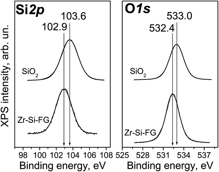 | ||
| Fig. 1 Si2p and O1s XPS core-level spectra of Zr–S-FG sample in comparison with SiO2. | ||
Fig. 2 shows kinetic dependencies for Si, Zr, and Na obtained at Zr–Si-FG differential dissolution. Since the concentration of Si, Zr, and Na varied by 4 orders, time profiles of kinetic dependencies were normalized to the maximum dissolution rate for each element which allowed presenting the dependence of all components in the same scale. For the sample with homogeneous distribution of the components in the bulk, the normalized dependencies for all elements should merge into a single curve.17 However, it can be seen that the kinetic dependencies of the elements are not merged into one indicating a non-uniform distribution of the elements with depth (Fig. 2). An exception is the ending part of Si and Zr kinetic dependencies merged into one. It should be noted that a small impurity of Na is located in the bulk of glass fibers which confirms the impossibility of complete removal of Na by the leaching process.
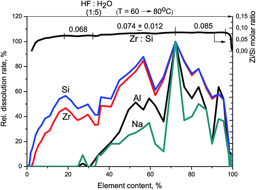 | ||
| Fig. 2 Kinetic dependencies of Na, Zr, and Si and Zr/Si stoichiogram obtained at Zr–Si-FG sample dissolution. Relative dissolution rate means the dissolution rate for each element referred to its maximal value. | ||
At the beginning of dissolution, the Zr/Si ratio is equal to zero (Fig. 2) which indicates the presence of acid-soluble silicon in the subsurface layers of fibers (Si-I form), i.e. the surface of the sample is enriched with silicon. Then, the Zr/Si ratio increases up to the average value of 0.074. The area of dissolution with the increased zirconium content (Zr/Si = 0.085) corresponds to the dissolution of Si-II form of silicon, while the area with the reduced zirconium content (Zr/Si = 0.068) corresponds to the joint dissolution of Si-I and Si-II forms. The Si-I form of silicon (Zr free) is located on the surface and in the subsurface layers of fibers and is clearly visible in Fig. 3. The chemical properties of the Si-I form (the ability to dissolve in HCl) are characteristic for the hydrated form of silica.17 The residual amounts of the Si-I form which were not dissolved completely in HCl continued to dissolve in HF. Stoichiographic calculations allow to separate the two forms of silicon (Fig. 4) and to quantify the content of the Si-I and Si-II forms (Table 2). Thus, DDPA data showed that the bulk of glass fibers is a spatially non-uniform Zr–Si structure of variable composition with the average ratio of Zr/Si equal to 0.074 ± 0.012.
 | ||
| Fig. 3 Kinetic dependencies of Na, Zr, and Si and Zr/Si stoichiogram obtained at Zr–Si-FG sample dissolution. | ||
 | ||
| Fig. 4 Kinetic dependencies of Zr0.074Si1 and Si-I dissolution for Zr–Si-FG sample. | ||
| Sample | Element content, % | |||
|---|---|---|---|---|
| Si-I | Si-II Zr0.074Si1 | Co-I | Co-II | |
| Zr–Si-FG | 10.2 | 89.8 | — | — |
| Co/Zr–Si-FG | 1.08 | 98.9 | 0.018 | 0.002 |
Fig. 5 shows the UV-Vis DR spectrum of Zr–Si-FG (spectrum 1). It can be seen that there is a strong absorption peak in the UV region with a maximum at 44700 cm−1, probably appeared from the absorption of Zr–Si-FG itself like other oxygen-containing systems.23,24 The absorption bands of glass forming elements such as Si4+ and Zr4+ cations are not revealed in the visible region of UV-Vis DR spectrum of Zr–Si-FG (spectrum 1), which will allow us to interpret unambiguously the absorption bands of Co/Si–Zr-FG appearing in this spectrum region.
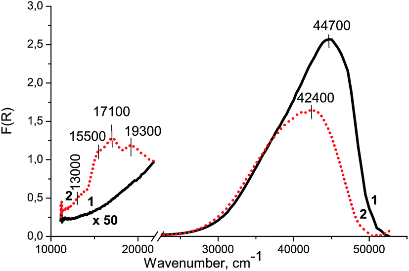 | ||
| Fig. 5 UV-Vis-NIR DR spectra of Zr–Si-FG (1) and Co/Zr–Si-FG (2) samples. | ||
3.2. Physicochemical properties of Co/Zr–Si-FG
The XPS spectra of Co/Zr–Si-FG were registered at 0, 2, 7, and 17 min of the ion sputtering. It was found that Si and O elements predominate in the structure of Co/Zr–Si-FG, while the concentration of Zr and especially Co is quite low. The impurities of other elements were not found. The results of quantitative analysis are shown in Table 3.| Etching time, min | [Zr]/[Si] | [Co]/[Si] | [O]/[Si + Zr] | [O]/[Si] |
|---|---|---|---|---|
| 0 | 0.0034 | 0.012 | 2.2 | 2.2 |
| 2 | 0.0054 | 0.011 | 2.2 | 2.2 |
| 7 | 0.024 | 0.0069 | 2.0 | 2.1 |
| 17 | 0.090 | 0.0055 | 2.1 | 2.3 |
The Si2p and O1s binding energies are 103.5 and 532.8 eV, respectively, which is typical for polycrystalline SiO2.19,25,26 Cobalt is mainly localized on the surface of Zr–Si-FG and its concentration drops distinctly after several minutes of the ion sputtering (Fig. 6). In contrast, the concentration of Zr increases with increase in the depth of analysis.
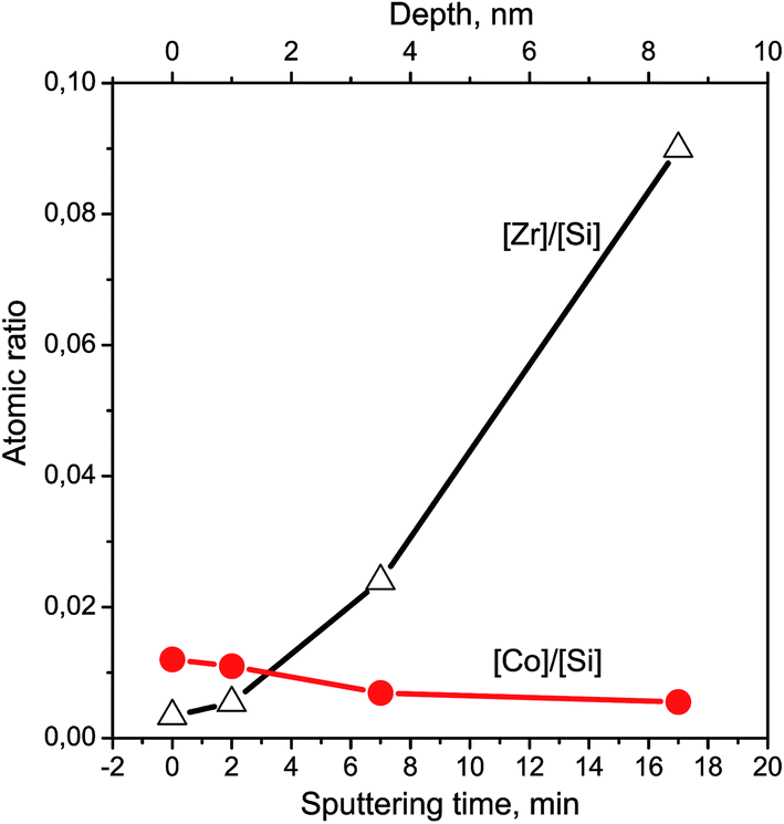 | ||
| Fig. 6 Cobalt and zirconium depth-profiles for Co/Zr–Si-FG sample. | ||
The Zr3d spectrum of Co/Zr–Si-FG registered after 7 min of the ion sputtering is shown in Fig. 7. It can be seen that the spectrum is a doublet with the intensity of Zr3d5/2 and Zr3d3/2 components related as 3:2. The difference in the Zr3d5/2 and Zr3d3/2 binding energies (spin–orbit splitting) is 2.4 eV. The Zr3d5/2 binding energy is 183.8 eV which corresponds to Zr4+. The binding energies for zirconium silicate or for zirconium doped mesoporous silicates are similar (183.0–183.3 and 183.1–183.6 eV, respectively).20,21 The typical values of the Zr3d5/2 binding energies for stoichiometric ZrO2 are smaller and are in the range of 181.6–182.2 eV.20,21,27–29 The high-dispersed particles of ZrO2 with the sizes ranging from 6 to 100 nm are characterized by even a lower value of the Zr3d5/2 binding energies (180.8–181.7 eV), and the binding energy increases with an increase in the particle size.27 The Zr3d5/2 binding energy for a ZrO2–Si thin film is 182.7 eV.29 Therefore, we can assume that the Zr4+ cations are included in the structure of glass matrix but do not form ZrO2 oxide particles. This is in a good agreement with the framework structure of Zr–Si glass fibers revealed in NMR and IR spectroscopic studies.30
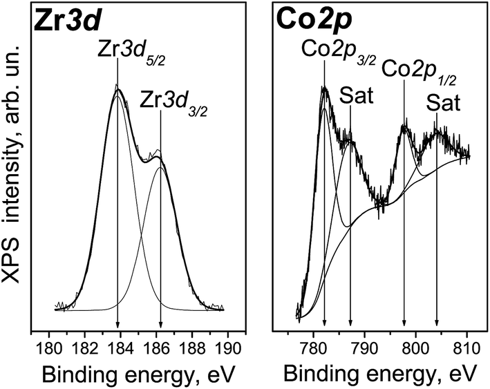 | ||
| Fig. 7 Co2p and Zr3d spectra of Co/Zr–Si-FG sample. | ||
Fig. 7 shows the Co2p spectrum of Co/Zr–Si-FG surface. It can be seen that along with the Co2p3/2 and Co2p1/2 sharp peaks at 781.8 and 797.5 eV, respectively, there are intense bands of so-called “shake-up” satellites shifted by 6 eV towards higher binding energy values. The presence of intense satellites is a characteristic feature of Co2+ cations.29,31,32 Indeed, “shake-up” satellites are practically absent in the spectra of trivalent cobalt compounds and cobalt in the metallic state.31,32 The value of spin–orbit splitting (i.e. the difference in the Co2p1/2 and Co2p3/2 binding energies) for Co/Zr–Si-FG is 15.7 eV. This is in a good agreement with the literature data on Co2+ compounds (CoO, Co(OH)2) with the spin–orbit splitting of 15.5–16.0 eV, whereas the spin–orbit splitting for trivalent cobalt stabilized in the LiCoO2 structure is only 15.0 eV.31,32 Therefore, the cobalt on the Co/Zr–Si-FG surface is predominantly in the Co2+ state.
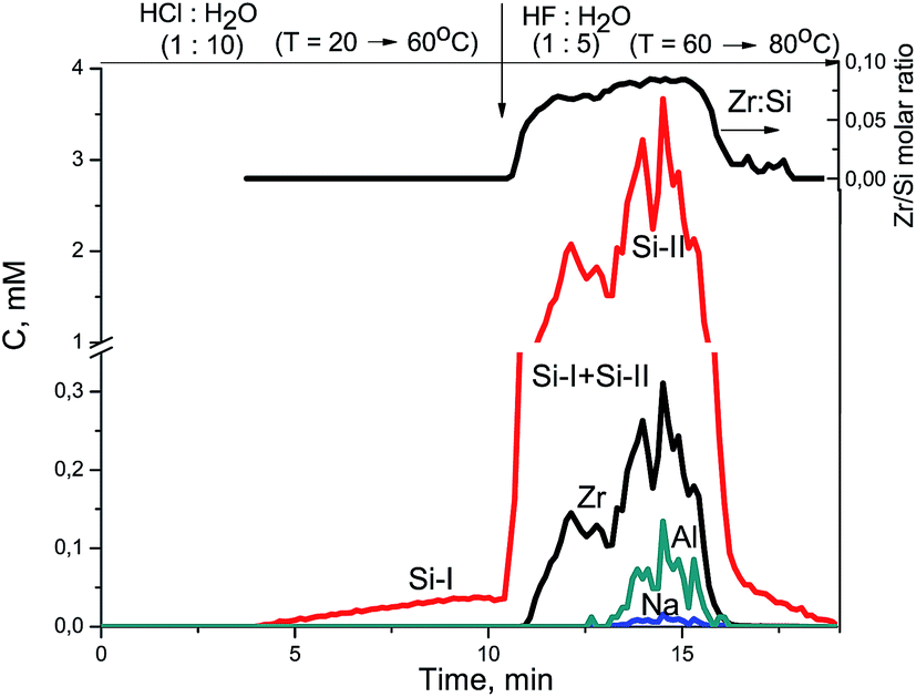
Fig. 8 shows kinetic dependencies of Si, Zr, and Co obtained at the Co/Zr–Si-FG differential dissolution. Cobalt kinetic dependency contains two areas of intense dissolution. The first area of kinetic dependency corresponds to a Co-I form which dissolves simultaneously with the surface layers of fibers (up to 5% of soluble part of Co/Zr–Si-FG). Diffusion and structural limitations associated with the Zr–Si-FG structure prevent the rapid dissolution of the surface Co-I form and, thus, affect the form of the cobalt kinetic dependency. The second area corresponds to the dissolution of a Co-II form. This is a bulk form of cobalt dissolving in HF together with framework elements of glass fibers under the DDPA dynamic mode. Therefore, the cobalt is present not only on the surface and in the subsurface layers of glass fibers but also in the bulk of fibers.
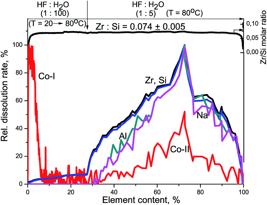 | ||
| Fig. 8 Kinetic dependencies of Zr, Co, and Si and Zr/Si stoichiogram obtained at Co/Zr–Si-FG sample dissolution. Relative dissolution rate means the dissolution rate for each element referred to its maximal value. | ||
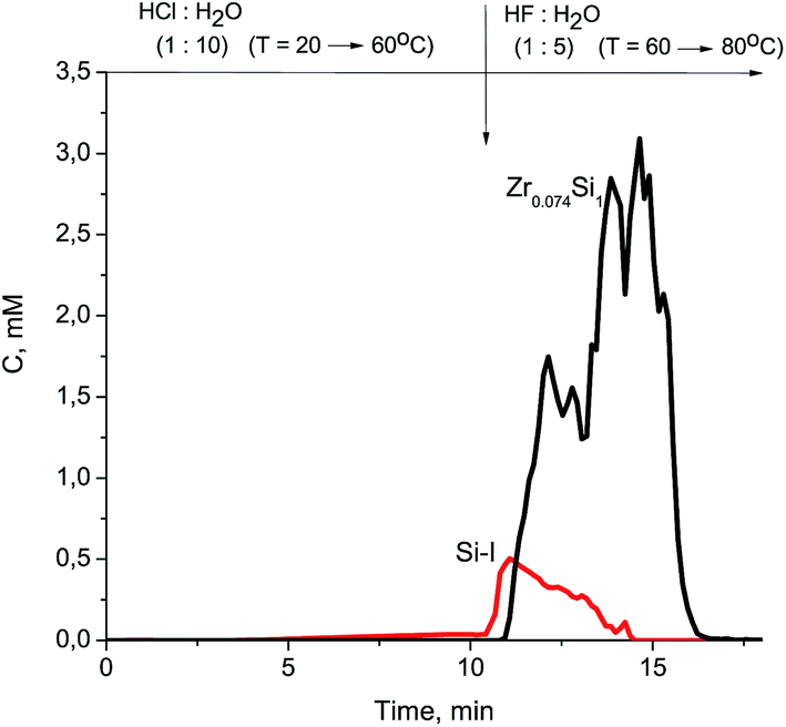
The Zr/Si stoichiogram (Fig. 8) is linear and corresponds to the ZrxSi1 formula (x = 0.074 ± 0.005) with an accuracy corresponding to a deviation of the glass fibers composition from the homogeneous distribution of the components in the bulk. The differences in the framework formulas of Zr–Si-FG and Co/Zr–Si-FG are only in numeric errors (0.012 and 0.005, respectively), which depends on the method of Co/Zr–Si-FG synthesis and the conditions of dissolution.33
The subsurface layers of the Co/Zr–Si-FG sample have a variable value of the Zr/Si molar ratio (from zero to 0.074). Alternating character of the Zr/Si stoichiogram in the first minutes of dissolution indicates the presence of hydrated form of silicon (Si-I) at the surface of Co/Zr–Si-FG similarly to that of Zr–Si-FG. The dissolution of hydrated form of silica detected on the surface of Co/Zr–Si-FG is accompanied by a simultaneous dissolution of bulk silicon. Only stoichiographic calculations allow to divide both forms of silicon and to show the kinetics of dissolution (Fig. 9), as well as to quantify the content of the Si-I hydrated form, and the Si-II framework form in Co/Zr–Si-FG (see Table 2). As follows from Table 2, the ratio of Co-I form to Si-I form in Co/Zr–Si-FG sample is equal to 0.017%, which corresponds, according to XPS (Fig. 6 and Table 3), to the surface hydrated silicon layer of 6 nm in depth.
 | ||
| Fig. 9 Kinetic dependencies of Zr0.074Si1, Co, and Si-I from dissolution for Co/Zr–Si-FG sample. | ||
Thus, the DDPA data showed that modification of Zr–Si-FG by Co2+ cations led to distribution of 90% of the total cobalt content on the surface and in the subsurface layers of Zr–Si-FG including surface silica layer. The remaining 10% of the cobalt were dissolved simultaneously with Si–Zr-framework, indicating the presence of cobalt in the bulk of glass fibers. The shape of kinetic dependencies of the cobalt dissolution (Co-II part) indicates a spatially non-uniform distribution of Co in the bulk of Zr–Si-FG.
Fig. 5 shows the UV-Vis DR spectrum of Co/Zr–Si-FG sample. There are three absorption bands in the visible region of spectrum: at 13000, 15500, 17100, and 19300 cm−1, and a strong absorption in the near UV region above 30000 cm−1 with a maximum at 42400 cm−1, similar to Zr–Si-FG sample.
4. Discussion
The XPS study revealed the presence of a hydrated silicon compound stabilized on the surface of glass fibers which is in a good agreement with the literature data.22,34 This layer of silicon compound most probably consists of oligomeric forms of silicic acid (SiOn(OH)m species). According to the DDPA data (Fig. 9, Table 2), 90% of cobalt in Co/Zr–Si-FG was dissolved simultaneously with a surface silicon layer. The Co/Si stoichiogram has a variable character that indicates the absence of the interaction phase between cobalt and silicon. Apparently, the cobalt is distributed non-uniformly in the silicon layer. The remaining 10% of the cobalt was detected in the bulk of Co/Zr–Si-FG.The absorption in the region of 15000–17000 cm−1 is generally related to the d–d transition of Co2+Td appearing as one, two or three absorption bands in the UV-Vis DR spectra.7,18,32,33 Therefore, the absorption bands at 15500 and 17100 cm−1 (Fig. 5) can be attributed to the weak appearance of multiplet structure of d–d transition (4A2(F)–4T1(P)) of Co2+ cations in the tetrahedral oxygen coordination (Co2+Td). According to the scheme of splitting of the electron 4F-term in weak crystal fields with the symmetry of tetrahedron distorted along the trigonal axis, the multiplet of absorption bands of Co2+ cations is observed in the case of trigonal distortion of the tetrahedron, its compression or stretching.35 At compression of the tetrahedron, all the intensities of the absorption bands are different and consistently increase or decrease during the transition from one absorption band to another. This type of multiplet of absorption bands is observed, for example, for CoAl2O4 and γ-Co(OH)2.36,37 At tetrahedron stretching, the intensity of the first and third absorption bands is the same, and the intensity of the middle absorption band is lower or higher than that of two neighbor bands. This is usually observed for isolated Co2+Td cations stabilized in zeolite channels, for example, X and Y, when the oxygen of the zeolite lattice is one of the ligands, and the water molecules are the other three ligands.35 If there is no trigonal distortion of the tetrahedron, one or two absorption bands can be seen in the UV-Vis DR spectra, since there is no removal of the degeneracy of the overlying T1 and T2 terms. Therefore, we do not observe splitting of terms which usually manifests itself in the form of absorption bands in the UV-Vis DR spectrum of Co2+Td cations.
The shoulder of low intensity at 13000 cm−1 refers to a two-electron d–d transition (4T1g(F)–4A2g(F)) of Co2+ cations in the octahedral oxygen coordination (Co2+Oh). The band at 19300 cm−1 is attributed to the d–d transition (4T1g(F)–4T1g(P)) of Co2+ cations in the octahedral oxygen coordination (Co2+Oh).18,37
It can be assumed that the weak appearance of the multiplet structure of absorption bands in the UV-Vis DR spectra is due to squeezing of the tetrahedron around Co2+ cations. This can take place only in the case of Co2+ localization in the positions of Si4+ in the hydrated silicon compound stabilized on the surface of Zr–Si-FG. It is well known that the modifiers introduced after the synthesis of fiberglass material are most often localized not only on the surface of fiber but in the bulk of glass matrix in narrow (<4 Å) low-density spaces.30,38 These low-density spaces are filled with H-bonded hydroxyl groups which is one of the key features of silicon glass structure.30 Squeezing the tetrahedron around Co2+ cations is probably associated with a larger ion radius of cobalt as compared with that of Si4+. Co2+ cations in tetrahedral coordination are stabilized in the cavities of the hydrated layer of Si-I form as most probably the dimers of tetrahedral Co2+ cations of <10 Å in size, like a very small Pd clusters around 1 nm in size in glass matrix.39
Recently, it was shown that an increase in the calcination temperature for Co-containing SiO2 up to 600 °C led to the interaction of Co2+Oh cations with Si4+ cations with formation of Co2SiO4; the absorption bands for Co2SiO4 appeared in the visible region of UV-Vis spectrum at 13000 and 22000 cm−1.9 In our case, the XPS and DDPA data showed that the calcination of Co/Zr–Si-FG at 550 °C did not lead to the formation of Co2SiO4. Besides, the absorption bands at 13000 and 19300 cm−1 were observed in the UV-Vis DR spectrum of Co/Zr–Si-FG sample (Fig. 5, curve 2), therefore, Co2+ cations represent the isolated hexaaquacomplexes of Co2+ like Co2+Oh in aqueous solutions of Co2+ salts, which do not incorporate into the lattice of Zr–Si-FG.18
Cava et al. showed that the variation of SiO2/ZrO2 ratios led to formation of solid solutions of isomorphic SiO2–ZrO2 substitution with different structure.10 According to the XPS data, the new compound was ZrSiO4 with a layer of SiO2 on the surface.10 After the impregnation with cobalt nitrate solution, the Co2+ cations were stabilized in the tetrahedral (in the positions of Si4+ in SiO2) and octahedral (in positions of Zr4+ in ZrSiO4) positions.10 In our case, the DDPA study showed that the framework of Zr–Si-FG and Co/Zr–Si-FG has the parametric formula of Zr0.074±0.012Si1 and Zr0.074±0.005Si1, respectively, indicating that zirconium is distributed statistically in the bulk of glass fiber and that the solid solution of ZrSiO4 is absent. The presence of an intermediate state between ZrO2 and ZrSiO4 is confirmed by difference in the binding energy values for Zr4+ in Zr–Si-FG. The difference in the binding energy values remains the same after modification of Zr–Si-FG with Co2+ cations. Based on these data, we can assume that the Co2+Oh cations are stabilized in the cavities of larger size in the bulk of Co/Zr–Si-FG in comparison with the cavities in the subsurface hydrated SiO2 containing dimers of Co2+Td cations.
The drop in intensity of the charge-transfer band in the UV-Vis DR spectrum (Fig. 5, curve 2) at 44700 cm−1 and its visible shift to 42400 cm−1 can indicate the compaction of the Co/Zr–Si-FG structure during calcination of the sample and reducing the amount and size of the cavities in the sample like in ZnO polycrystals. Thus, the cobalt cations are stabilized in Co/Zr–Si-FG both in the tetrahedral and octahedral oxygen coordination. Besides, the Co2+ cations do not form a new compound with Si4+ cations (like Co2SiO4), as well as a solid solution of CoO in ZrSiO4. Co3O4 normally appearing in the UV-Vis DR spectrum as a pair of absorption bands at 15000 and 22500 cm−1 was not detected. Therefore, it can be concluded that isolated Co2+ cations are stabilized in the bulk of Zr–Si-FG in the octahedral coordination and in the subsurface layers as dimers of Co2+ cations in the tetrahedral coordination.
On the basis of the set forth experimental and literature data, the influence of the hydrated silicon layer on the stabilization of the Co2+ cations in glass fibers may be described as follows. According to the literature, glass fibers contain the hydrated SiOn(OH)m on the surface, similar to [Si(OH)4]n.33,40 Zr4+ cations in the structure of ZrSiO4 have a coordination number of 8.41 The theoretical calculations of NMR spectra showed that Zr4+ cations are stabilized in the bulk of glass fibers in the octahedral oxygen coordination.30 Impregnation of glass fibers with an aqueous solution of CoCl2 containing only isolated Co2+Oh cations and drying at 20 °C leads to stabilization of cobalt cations only in octahedral coordination. Further calcination of Co/Zr–Si-FG sample at 550 °C results in two types of stabilization of Co2+ cations. A small fraction of Co2+ cations stabilizes in the bulk of glass fibers (Si-II form) as the isolated Co2+Oh cations. Most of Co2+ cations is stabilized in hydrated silicon layer (Si-I) of 6 nm in size in the form of Co2+Td dimers with the size of up to 10 Å.
5. Conclusions
The XPS and DDPA method showed that the surface of Zr–Si-FG contained the hydrated silicon layer which most probably was represented by oligomeric forms of silicic acid, i.e. SiOn(OH)m species. Zirconium was found to be distributed non-uniformly in the bulk of glass fibers. The modification of Zr–Si-FG by cobalt led to distribution of 90% of cobalt in the hydrated silicon layer (the dimers of Co2+ cations in the tetrahedral coordination) while the remaining part of cobalt was stabilized in the bulk of glass fibers (isolated Co2+ cations in the octahedral coordination).Acknowledgements
The authors thank V. A. Balashov for the preparation of the Co/Na–Zr–Si fiberglass material and A. A. Pochtar' for help with performing differential dissolution studies. Presidium of the Russian Academy of Sciences and Ministry of Education and Science of the Russian Federation are gratefully acknowledged for supporting the research.References
- L. Kiwi-Minsker, I. Yuranov, E. Slavinskaya, V. Zaikovskii and A. Renken, Catal. Today, 2000, 59, 61–68 CrossRef CAS.
- A. N. Zagoruiko, S. A. Lopatin, B. S. Bal'zhinimaev, N. R. Gil'mutdinov, G. G. Sibagatullin, V. P. Pogrebtsov and I. F. Nazmieva, Catal. Ind., 2010, 2, 113–117 CrossRef.
- B. S. Bal'zhinimaev, L. G. Simonova, V. V. Barelko, A. V. Toktarev, V. I. Zaikovskii and V. A. Chumachenko, Chem. Eng. J., 2003, 91, 175–179 CrossRef.
- B. S. Bal'zhinimaev, V. V. Barelko, A. P. Suknev, E. A. Paukshtis, L. G. Simonova, V. B. Goncharov, V. L. Kirillov and A. V. Toktarev, Kinet. Catal., 2002, 43, 542–549 CrossRef.
- E. A. Paukshtis, L. G. Simonova, A. N. Zagoruiko and B. S. Balzhinimaev, Chemosphere, 2010, 79, 199–204 CrossRef CAS PubMed.
- L. G. Simonova, V. V. Barelko, A. V. Toktarev, V. I. Zaikovskii, V. I. Bukhtiyarov, V. V. Kaichev and B. S. Bal'zhinimaev, Kinet. Catal., 2001, 42, 837–846 CrossRef CAS.
- O. P. Krivoruchko, V. Yu. Gavrilov, I. Yu. Molina and T. V. Larina, Kinet. Catal., 2008, 49, 285–290 CrossRef CAS.
- P. Shukla, H. Sun, Sh. Wang, H. M. Ang and M. O. Tade, Sep. Purif. Technol., 2011, 77, 230–236 CrossRef CAS.
- S. Esposito, A. Setaro, P. Maddalena, A. Aronne, P. Pernice and M. Laracca, J. Sol-Gel Sci. Technol., 2011, 60, 388–394 CrossRef CAS.
- S. Cava, S. M. Tebcherani, S. A. Pianaro, C. A. Paskocimas, E. Longo and J. A. Varela, Ceramica, 2005, 51, 302–307 CAS.
- S. P. Bardakhanov, A. I. Korchagin, N. K. Kuksanov, A. V. Lavrukhin, R. A. Salimov, S. N. Fadeev and V. V. Cherepkov, Mater. Sci. Eng., B, 2006, 132, 204–208 CrossRef CAS.
- J. H. Scofield, J. Electron Spectrosc. Relat. Phenom., 1976, 8, 129–137 CrossRef CAS.
- D. A. Shirley, Phys. Rev. B: Solid State, 1972, 5, 4709–4714 CrossRef.
- V. V. Malakhov and I. G. Vasilyeva, Russ. Chem. Rev., 2008, 77, 351–372 CrossRef CAS.
- V. V. Malakhov, J. Anal. Chem., 2009, 64, 1097–1107 CrossRef CAS.
- V. V. Malakhov and A. A. Vlasov, J. Anal. Chem., 2011, 66, 262–268 CrossRef CAS.
- V. V. Malakhov, N. N. Boldyreva, A. A. Vlasov and L. S. Dovlitova, J. Anal. Chem., 2011, 66, 458–464 CrossRef CAS.
- A. B. P. Lever, Inorganic Electronic Spectroscopy, Elsevier, Amsterdam, Oxford, New York, Tokyo, 2nd edn, 1987 Search PubMed.
- A. A. Khassin, T. M. Yurieva, M. P. Demeshkina, G. N. Kustova, I. Sh. Itenberg, V. V. Kaichev, L. M. Plyasova, V. F. Anufrienko, I. Yu. Molina, T. V. Larina, N. A. Baronskaya and V. N. Parmon, Phys. Chem. Chem. Phys., 2003, 5, 4025–4031 RSC.
- M. J. Guittet, J. P. Crocombette and M. Gautier-Soyer, Phys. Rev. B: Condens. Matter Mater. Phys., 2001, 63, 125117 CrossRef.
- D. J. Jones, J. Jimenez-Jimenez, A. Jimenez-Lopez, P. Maireles-Torres, P. Olivera-Pastor, E. Rodriguez-Castellon and J. Roziere, Chem. Commun., 1997, 431–432 RSC.
- T. S. Glazneva, V. V. Kaichev, E. A. Paukshtis, D. F. Khabibulin, O. B. Lapina, B. S. Bal'zhinimaev, E. N. Zhurba, I. A. Lavrinovich, I. N. Gavrikova, V. I. Shumskii and A. N. Trofimov, J. Non-Cryst. Solids, 2012, 358, 1053–1058 CrossRef CAS.
- L. Truffault, M.-T. Ta, T. Devers, K. Konstantinov, V. Harel, C. Simmonard, C. Andreazza, I. P. Nevirkovets, A. Pineau, O. Veron and J.-Ph. Blondeau, Mater. Res. Bull., 2010, 45, 527–535 CrossRef CAS.
- M. G. Ha, E. D. Jeong, M. S. Won, H. G. Kim, H. K. Pak, J. H. Jung, B. H. Shon, S. W. Bae and J. S. Lee, J. Korean Phys. Soc., 2006, 49, S675–S679 CAS.
- S. B. Hong and M. A. Camblor, Chem. Mater., 1997, 9, 1999–2003 CrossRef CAS.
- J. Mendialdua, R. Casanova, F. Rueda, A. Rodriguez, J. Quinones, L. Alarcon, E. Escalante, P. Hofmann, I. Taebi and L. Jalowiecki, J. Mol. Catal. A: Chem., 2005, 228, 151–162 CrossRef CAS.
- S. Tsunekawa, K. Asami, S. Ito, M. Yashima and T. Sugimoto, Appl. Surf. Sci., 2005, 252, 1651–1656 CrossRef CAS.
- C. Sleigh, A. P. Pijpers, A. Jaspers, B. Coussens and R. J. Meier, J. Electron Spectrosc. Relat. Phenom., 1996, 77, 41–57 CrossRef CAS.
- N. S. Mclntyre and M. G. Cook, Anal. Chem., 1975, 47, 2208–2213 CrossRef.
- B. S. Bal'zhinimaev, E. A. Paukshtis, O. B. Lapina, A. P. Suknev, V. A. Kirillov, P. E. Mikenin and A. N. Zagoruiko, Stud. Surf. Sci. Catal., 2010, 175, 43–50 CrossRef.
- A. A. Khassin, T. M. Yurieva, V. V. Kaichev, V. I. Bukhtiyarov, A. A. Budneva, E. A. Paukshtis and V. N. Parmon, J. Mol. Catal. A: Chem., 2001, 175, 189–204 CrossRef CAS.
- N. V. Kosova, V. V. Kaichev, V. I. Bukhtiyarov, D. G. Kellerman, E. T. Devyatkina and T. V. Larina, J. Power Sources, 2003, 119–121, 669–673 CrossRef CAS.
- L. S. Dovlitova, A. A. Pochtar and V. V. Malakhov, J. Anal. Chem., 2013, 68, 72–79 CrossRef CAS.
- C. Cailleteau, F. Angeli, F. Devreux, S. Gin, J. Jestin, P. Jollivet and O. Spalla, Nat. Mater., 2008, 7, 978–983 CrossRef CAS PubMed.
- I. D. Mikheikin, O. I. Brotikovskii, G. M. Zhidomirov and V. B. Kazanskii, Kinet. Katal., 1971, 12, 1442–1447 CAS.
- O. P. Krivoruchko, V. F. Anufrienko, E. A. Paukshtis, T. V. Larina, E. B. Burgina, S. A. Yashnik, Z. R. Ismagilov and V. N. Parmon, Dokl. Phys. Chem., 2004, 398, 226–230 CrossRef CAS.
- O. P. Krivoruchko, T. V. Larina, V. F. Anufrienko, I. Yu. Molina and E. A. Paukshtis, Inorg. Mater., 2009, 45, 1355–1361 CrossRef CAS.
- Yu. K. Gulyaeva, A. P. Suknev, E. A. Paukshtis and B. S. Bal'zhinimaev, J. Non-Cryst. Solids, 2011, 357, 3338–3344 CrossRef CAS.
- Yu. K. Gulyaeva, V. V. Kaichev, V. I. Zaikovskii, E. V. Kovalyov, A. P. Suknev and B. S. Bal'zhinimaev, Catal. Today, 2015, 245, 139–146 CrossRef CAS.
- R. K. Iler, The chemistry of silica: solubility, polymerization, colloid and surface properties and biochemistry of silica, Wiley-Interscience, New York, Chichester, Brisbano, Toronto, 1979 Search PubMed.
- T. Kittiauchawal, A. Mungchamnankit, S. Sujinnapram, J. Kaewkhao and P. Limsuwan, Procedia Eng., 2012, 32, 706–713 CrossRef CAS.
| This journal is © The Royal Society of Chemistry 2015 |