Understanding effects of two different acceptors in one small molecule for solution processable organic solar cells†
Yifan Zhaoab,
Liu Yuanb,
Jianqi Zhangb,
Lingyun Zhub,
Kun Lu*b,
Wei Yan*a and
Zhixiang Wei*b
aDepartment of Environmental Science and Engineering, Xi’an Jiaotong University, Xi’an 710049, China. E-mail: yanwei@mail.xjtu.edu.cn
bNational Center for Nanoscience and Technology, Beijing 100190, China. E-mail: lvk@nanoctr.cn; weizx@nanoctr.cn
First published on 3rd July 2015
Abstract
Introducing two different electron-withdrawing groups into the molecular backbone is one of the effective methods to extend absorption and lower the highest occupied molecular orbital (HOMO) energy level for a high open-circuit voltage (Voc). However, examples of two-acceptor type small molecules are less studied. In order to understand the effect of two acceptors, two kinds of small molecules named as BDT(dFBT-TT)2 with a single acceptor unit and BDT(dFBT-ON)2 with two acceptor units have been synthesized, respectively. However, the power conversion efficiency (PCE) of the BDT(dFBT-ON)2 device is lower (3.54%) than that of BDT(dFBT-TT)2 (5.55%). Grazing incidence wide angle X-ray scattering (GIWAXS) and the intensity dependence of current–voltage characteristics were used to study the spatially periodic order and charge recombination of these small molecules. Although the Voc of BDT(dFBT-ON)2 is higher than that of BDT(dFBT-TT)2, the short circuit current (Jsc) of BDT(dFBT-ON)2 is lower due to a higher ratio of charge carrier recombination. For the sake of getting a high Voc and Jsc simultaneously in the future, this work would supply valuable insights for designing multi-acceptor-type small molecules.
Introduction
With the decline of traditional energy sources and increasing pollution, the development and application of clean energy is extremely urgent. Solar energy, with its many features such as being reproducible, pollution-free and inexhaustible, has kept research enthusiasm going for years. Organic solar cells (OSCs) are superior compared with mainstream silicon cells in the manner of being low-cost, having a simple preparation, being producible on a large-scale, and being solution processable. The bulk heterojunction (BHJ), which is proven to be the most successful structure currently, can realize the function of a p-type semiconductor (polymer or small molecule) as the electron donor (D) and a fullerene derivative ([6,6]-phenyl-C-butyric acid methyl ester, PCBM) as the electron acceptor (A).1–3 Recently, the power conversion efficiency (PCE) of single junction OSCs has approached over 10%, both in polymer and small molecule solar cells.4,5 Compared with the polymer donor materials, small molecules have many advantages such as a reproducible synthesis and purification, good solubility, high mobility, well-defined structures and no batch to batch variations.6 On the other hand, small molecules are beneficial for forming a good nanoscale film morphology.7 Hence, small molecules attract more research that is interesting in the OSCs field.For achieving a high PCE, the molecule design should be carried out carefully to get broad absorption, a lower highest occupied molecular orbital (HOMO) level, high mobility, and so on.8 Some works have reported adding two acceptor units into a polymer or small molecule structure to extend the absorption edge and lower the HOMO levels.9–17 However, this kind of small molecule did not show high photovoltaic properties,15,16 and a deep understanding of the roles for the two acceptors in one small molecule had barely been demonstrated.
As strong acceptor units, 5,6-difluoro-2,1,3-benzothiadiazole (dFBT) and oxo-alkylated nitrile (ON) groups are mostly used in the polymers and small molecules to lower the HOMO level and achieve a high PCE over 9%.6,16,18–22 In addition, benzo[1,2-b:4,5-b]dithiophene (BDT) has been proven to be a very good donor unit both in polymers and small molecules.5,23–26 Moreover, adding two different acceptors into the main frame structure of the small molecule may enhance the electron-withdrawing ability and interaction between the molecules.
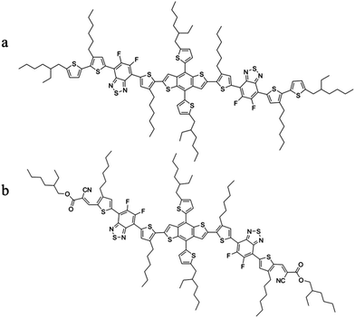
In this paper, we synthesized two kinds of small molecules named BDT(dFBT-ON)2 with the structure of A1–A2–D–A2–A1 and BDT(dFBT-TT)2 with the structure of D1–A2–D–A2–D1 using the BDT unit as D, and ON and dFBT as A1 and A2, respectively. The photovoltaic properties and film morphology were both investigated and compared with each other. The crystalline behaviours and the spatially periodic order were also studied by grazing incidence wide angle X-ray scattering (GIWAXS). Interestingly, this study revealed that two acceptors resulted in a high open-circuit voltage (Voc) and a red-shifted absorption spectrum, but a high short circuit current (Jsc) can not emerge. In addition, atomic force microscopy (AFM) and transmission electron microscopy (TEM) were used to investigate the film morphology. The charge recombination of small molecules was also studied by the intensity dependence of the current–voltage characteristics to discuss the differences in properties. This work would supply valuable insights and play a guiding significant role in the design of A1–A2–D–A2–A1 style small molecules in the future to get both high Voc and Jsc values simultaneously.
Results and discussion
Materials and synthesis
The chemical structures of the molecules BDT(dFBT-TT)2 and BDT(dFBT-ON)2 are illustrated in Scheme 1, and their synthesis process can be seen in the ESI.†Optical and electrochemical properties
The normalized UV-vis absorption of the small molecules in chloroform solution and in a thin solid film is shown in Fig. 1. The optical spectrum of BDT(dFBT-ON)2 in chloroform presented an absorption peak at 544 nm and the thin film showed intense absorption throughout the visible region (300–750 nm). It exhibited an obvious red-shifted absorption peak (λmax = 609 nm) by introducing two different acceptor units compared with BDT(dFBT-TT)2 (λmax = 580 nm), and the red-shift was about 29 nm. The vibronic shoulder peaks were at 663 nm for BDT(dFBT-ON)2 and 633 nm for BDT(dFBT-TT)2, which indicated π–π packing between the molecular backbones and strong intermolecular interaction in the solid state. The film absorption onsets of BDT(dFBT-ON)2 and BDT(dFBT-TT)2 were 740 nm and 713 nm, and their corresponding optical band gaps were −1.68 eV and −1.75 eV, respectively. This red-shift can be attributed to the introduction of the two acceptors of the ON group and the dFBT group.13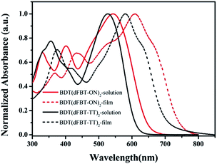 | ||
| Fig. 1 UV-vis absorption spectra of BDT(dFBT-TT)2 and BDT(dFBT-ON)2 in chloroform solution and in a solid film. | ||
The energy levels of the small molecules were measured by cyclic voltammetry (Fig. 2). The HOMO and lowest unoccupied molecular orbital (LUMO) energy levels of BDT(dFBT-ON)2 were −5.30 eV and −3.61 eV, calculated from the oxidation and reduction onset potential against Ag/Ag+.27 The value of LUMOD–LUMOA was large enough as a downhill driving force for exciton dissociation.28–32 The energy levels of BDT(dFBT-TT)2 were −5.25 eV and −3.53 eV. Obviously, two-acceptors can be a stronger electron-deficient group than a single-acceptor, which will lead to a narrower band gap with a deeper localized HOMO level.33 Otherwise, the deeper localized HOMO level of BDT(dFBT-ON)2 should get a higher Voc.
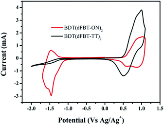 | ||
| Fig. 2 Cyclic voltammogram of the BDT(dFBT-TT)2 and BDT(dFBT-ON)2 films in 0.1 mol L−1 Bu4NPF6 acetonitrile solution. | ||
Geometry and electronic structure
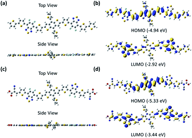
The ground-state geometry of these small molecules was optimized by density functional theory (DFT) at the B3LYP/6-31G(d,p) level, which was performed in the gas phase with the Gaussian 09 program.34 For the sake of calculation, the alkyl groups were replaced by hydrogen atoms. As seen from the optimized structures (Fig. 3), the backbones of the small molecules were both completely planar to form good π–π stacking in the film. The electrons of the HOMO were both localized mainly on the BDT unit and partly on the dFBT unit, and the electrons of the LUMO were localized mainly on the dFBT and ON units for BDT(dFBT-ON)2 and only on the dFBT unit for BDT(dFBT-TT)2. The DFT-derived HOMO and LUMO energy levels of the small molecules are seen from Fig. 3. All the results of the calculation were very consistent with the CV values.Photovoltaic properties
Photovoltaic devices were fabricated using indium-tin oxide (ITO) as the bottom electrode. The structure of the device was ITO/PEDOT:PSS/active layer/Ca/Al, in which the active layer was a blend of small molecules and PC71BM. Chloroform was chosen as the solvent for its good solubility.The ratio of small molecules to PC71BM was 1![[thin space (1/6-em)]](https://www.rsc.org/images/entities/char_2009.gif) :
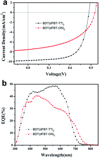
:![[thin space (1/6-em)]](https://www.rsc.org/images/entities/char_2009.gif) 1 (w/w). The best photovoltaic data are listed in Table 1. The corresponding current–voltage (J–V) curves and their external quantum efficiency (EQE) spectra are shown in Fig. 4. Some post-treatments such as thermal annealing, solvent annealing and additive solvent were all taken to improve the performance. However, thermal annealing and solvent annealing were not helpful to improve the performance of both the two molecules. The additive solvents, including 1,8-diiodooctane (DIO) and tetrahydrofuran (THF) (3% DIO and 1% THF, v/v), were added into the BDT(dFBT-ON)2 solution. The Voc, Jsc and fill factor (FF) were increased simultaneously and the best PCE was 3.54%.
1 (w/w). The best photovoltaic data are listed in Table 1. The corresponding current–voltage (J–V) curves and their external quantum efficiency (EQE) spectra are shown in Fig. 4. Some post-treatments such as thermal annealing, solvent annealing and additive solvent were all taken to improve the performance. However, thermal annealing and solvent annealing were not helpful to improve the performance of both the two molecules. The additive solvents, including 1,8-diiodooctane (DIO) and tetrahydrofuran (THF) (3% DIO and 1% THF, v/v), were added into the BDT(dFBT-ON)2 solution. The Voc, Jsc and fill factor (FF) were increased simultaneously and the best PCE was 3.54%.
![[thin space (1/6-em)]](https://www.rsc.org/images/entities/char_2009.gif) :
:![[thin space (1/6-em)]](https://www.rsc.org/images/entities/char_2009.gif) A ratios are 1
A ratios are 1![[thin space (1/6-em)]](https://www.rsc.org/images/entities/char_2009.gif) :
:![[thin space (1/6-em)]](https://www.rsc.org/images/entities/char_2009.gif) 1 (w/w)
1 (w/w)
| Small molecule | Voc (V) | Jsc (mA cm−2) | FF (%) | PCE (%) |
|---|---|---|---|---|
| BDT(dFBT-TT)2 | 0.86 | 9.19 | 65.9 | 5.55 |
| BDT(dFBT-ON)2 | 0.95 | 7.48 | 49.6 | 3.54 |
From the EQE curve of the optimized BHJ devices based on BDT(dFBT-ON)2![[thin space (1/6-em)]](https://www.rsc.org/images/entities/char_2009.gif) :
:![[thin space (1/6-em)]](https://www.rsc.org/images/entities/char_2009.gif) PC71BM (1
PC71BM (1![[thin space (1/6-em)]](https://www.rsc.org/images/entities/char_2009.gif) :
:![[thin space (1/6-em)]](https://www.rsc.org/images/entities/char_2009.gif) 1, w/w), a broader response range than that of BDT(dFBT-TT)2 was observed, which is consistent with the absorption spectrum. However, the value of the EQE indicated that the advantages of absorption did not reflect on the short circuit current. The integrated current densities from the EQE curves agree well with those obtained from the J–V curves with variations below 5%.
1, w/w), a broader response range than that of BDT(dFBT-TT)2 was observed, which is consistent with the absorption spectrum. However, the value of the EQE indicated that the advantages of absorption did not reflect on the short circuit current. The integrated current densities from the EQE curves agree well with those obtained from the J–V curves with variations below 5%.
Charge carrier mobility
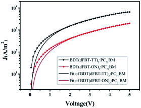
The blended films of small molecules with PC71BM were measured via hole-only space-charge-limited current (SCLC) diode mobility measurements,35 and the results are shown in Table 2. Fig. 5 shows the curve of J–V fitted according to the hole-only SCLC model. The charge carrier mobility differed by one order of magnitude for the two small molecules. In general, a high charge mobility deduced a high charge transform and low charge recombination. Therefore, the Jsc and FF were both obviously decreased for BDT(dFBT-ON)2 due to the lower mobility.![[thin space (1/6-em)]](https://www.rsc.org/images/entities/char_2009.gif) :
:![[thin space (1/6-em)]](https://www.rsc.org/images/entities/char_2009.gif) 1 (w/w)
1 (w/w)
| Materials | Additive solvents (v/v) | Thickness (nm) | Hole mobilities (cm2 V−1 s−1) |
|---|---|---|---|
| BDT(dFBT-TT)2:PC71BM | — | 109 | 6.17 × 10⁻⁴ |
| BDT(dFBT-ON)2:PC71BM | 3% DIO + 1% THF | 103 | 4.65 × 10⁻⁵ |
Film morphology
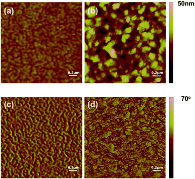
In order to understand the effect of film morphology on the solar cell performance and charge carrier mobility, AFM (Fig. 6) was carried out to characterize the features of the blended films. There was a big difference in morphology between the film of BDT(dFBT-TT)2:PC71BM and BDT(dFBT-ON)2:PC71BM. For the film of BDT(dFBT-ON)2:PC71BM with additive solvents, the scale of the phase separation was bigger and these aggregation structures limited the Jsc and FF values.36 The scale of the BDT(dFBT-TT)2:PC71BM domains decreased which was beneficial for the charge dissociation.37The TEM measurement (Fig. 7) was also taken to investigate the film morphology. Discrepancies were apparent in the morphology. Short nanorods can be observed in Fig. 7a. Otherwise, from Fig. 7b, apparent nanofiber domains appeared, and they were like continuous compact-networks throughout the film compared with the nanoflakes. The linear fiber structures were found when DIO was added into the solution of BDT(dFBT-ON)2 with PC71BM (see Fig. S3†), which had a positive effect on the charge separation and transfer.38 The linear fiber structure aggregated to be longer and stacked after THF was added into the blended film (see Fig. 7b). The dense dark domains are attributed to PC71BM rich regions39–41 and obvious crystallization can be observed. In general, the nanofibrous morphology brought about the enhancement of hole mobility due to the nanofibers being helpful for providing better charge transport pathways.42 The result of the TEM was accidentally inconsistent with the consequence of the charge mobility and solar cell performance. In fact, the performance of BDT(dFBT-TT)2 was better than that of BDT(dFBT-ON)2. Therefore, other methods need to be used to study the differences.
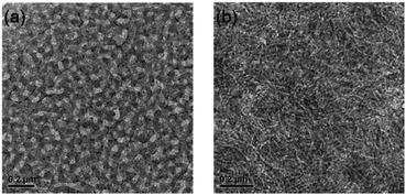 | ||
| Fig. 7 TEM images of the active layer of small molecules: (a) blended film of BDT(dFBT-TT)2:PC71BM; (b) blended film of BDT(dFBT-ON)2:PC71BM with 3% DIO and 1% THF. The scales are both 200 nm. | ||
Spatially periodic order
In order to study the molecular stacking and arrangement in the active layer, GIWAXS was performed. The results are shown in Fig. 8. From the 2D patterns (Fig. 8a and b), the samples showed a strong (100) peak in the out-of-plane direction, which means that the small molecules exhibit a preferential edge-on arrangement.38,43 However, the diffraction peak (010) of the π–π stacking can also be observed in the out-of-plane direction for BDT(dFBT-TT)2, while the (010) peak of BDT(dFBT-ON)2 can not be observed. It indicates that there is a portion of face-on orientation of BDT(dFBT-TT)2, however, it is not the case for BDT(dFBT-ON)2. It is well known that face-on orientation facilitates the charge transport between two electrodes.44,45 That is the main reason why BDT(dFBT-TT)2 has a better performance than BDT(dFBT-ON)2 from the molecular orientation point of view.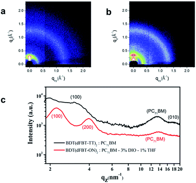 | ||
| Fig. 8 GIWAXS of small molecule based solar cell active layers: (a) BDT(dFBT-TT)2:PC71BM; (b) BDT(dFBT-ON)2:PC71BM, 3% DIO, 1% THF; (c) XRD patterns of BDT(dFBT-TT)2 and BDT(dFBT-ON)2 blended films. | ||
Intensity dependence of current–voltage characteristics
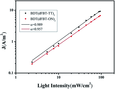
Two acceptors were helpful to extend the absorption edge and lower the HOMO level. In addition, the mixed solvents treatment was an effective method to modulate the morphology of the continuous nanofibers. Nevertheless, the photovoltaic performance was still not high. Hence, to get deeper insight into the charge recombination kinetics, studies were taken from the perspective of the Jsc under different light intensities ranging from 100 mW cm−2 to 0.5 mW cm−2. In this model, the variation of Jsc is dependant on a function of the illumination intensity (see Fig. S5†).46 The following equation shows a power law dependence of Jsc upon light intensity.| Jsc ∝ Iα |
From the equation, when α is close to unity, this is taken as being indicative of a weak bimolecular recombination.47–49 In Fig. 9, the data were plotted on a log–log scale and fitted to a power law using the equation. BDT(dFBT-TT)2 yields an α value of 0.989, compared with the α value of the BDT(dFBT-ON)2 based solar cell, which was closer to unity. A higher slope implies lower charge recombination and a higher charge dissociation efficiency.46,50 This was in agreement with the hole mobility and photovoltaic properties of the two small molecules.
Conclusions
A kind of two-A type small molecule named as BDT(dFBT-ON)2 and a single-A type small molecule named as BDT(dFBT-TT)2 were synthesized and their photovoltaic devices were fabricated. Introducing two different acceptor units into the small molecule could lower the HOMO level and extend the absorption area. As a result, the Voc of BDT(dFBT-ON)2 that could be reached was almost 1 V but the Jsc was not enhanced. Although some post-treatments such as adding DIO and THF additive solvents into the solution were taken to improve the morphology, the OSCs of BDT(dFBT-ON)2 exhibited low Jsc and FF values. In order to get an insight into this phenomenon, a study of the charge recombination was carried out and it was found that the two-acceptors would increase the charge recombination. The result illustrates that two acceptor (dFBT and ON) units in the backbone will decrease the charge dissociation efficiency and impact the Jsc and FF values. This work would supply valuable guidelines for the design of A1–A2–D–A2–A1 style small molecules for achieving high PCE values in the future, by tuning and choosing appropriate A1 and A2 units, in order to get a high Voc and Jsc simultaneously.Acknowledgements
We acknowledge the financial support of the National Natural Science Foundation of China (No. 21125420, 21474022), the Ministry of Science and Technology of China (No. 2011CB932303), and the Chinese Academy of Sciences.References
- L.-M. Chen, Z. Hong, G. Li and Y. Yang, Adv. Mater., 2009, 21, 1434–1449 CrossRef CAS PubMed.
- P. W. M. Blom, V. D. Mihailetchi, L. J. A. Koster and D. E. Markov, Adv. Mater., 2007, 19, 1551–1566 CrossRef CAS PubMed.
- R. L. Uy, S. C. Price and W. You, Macromol. Rapid Commun., 2012, 33, 1162–1177 CrossRef CAS PubMed.
- S. H. Liao, H. J. Jhuo, Y. S. Cheng and S. A. Chen, Adv. Mater., 2013, 25, 4766–4771 CrossRef CAS PubMed.
- B. Kan, Q. Zhang, M. Li, X. Wan, W. Ni, G. Long, Y. Wang, X. Yang, H. Feng and Y. Chen, J. Am. Chem. Soc., 2014, 136, 15529–15532 CrossRef CAS PubMed.
- Y. Chen, X. Wan and G. Long, Acc. Chem. Res., 2013, 46, 2645–2655 CrossRef CAS PubMed.
- W. Shin, T. Yasuda, G. Watanabe, Y. S. Yang and C. Adachi, Chem. Mater., 2013, 25, 2549–2556 CrossRef CAS.
- J. Roncali, P. Leriche and P. Blanchard, Adv. Mater., 2014, 26, 3821–3838 CrossRef CAS PubMed.
- B. Carsten, J. M. Szarko, H. J. Son, W. Wang, L. Lu, F. He, B. S. Rolczynski, S. J. Lou, L. X. Chen and L. Yu, J. Am. Chem. Soc., 2011, 133, 20468–20475 CrossRef CAS PubMed.
- J. E. Donaghey, R. S. Ashraf, Y. Kim, Z. G. Huang, C. B. Nielsen, W. Zhang, B. Schroeder, C. R. G. Grenier, C. T. Brown, P. D’Angelo, J. Smith, S. Watkins, K. Song, T. D. Anthopoulos, J. R. Durrant, C. K. Williams and I. McCulloch, J. Mater. Chem., 2011, 21, 18744–18752 RSC.
- K. H. Hendriks, G. H. Heintges, V. S. Gevaerts, M. M. Wienk and R. A. Janssen, Angew. Chem., Int. Ed., 2013, 52, 8341–8344 CrossRef CAS PubMed.
- J. W. Jung, F. Liu, T. P. Russell and W. H. Jo, Energy Environ. Sci., 2013, 6, 3301–3307 CAS.
- T. E. Kang, H.-H. Cho, H. J. Kim, W. Lee, H. Kang and B. J. Kim, Macromolecules, 2013, 46, 6806–6813 CrossRef CAS.
- S. Li, Z. Yuan, J. Yuan, P. Deng, Q. Zhang and B. Sun, J. Mater. Chem. A, 2014, 2, 5427–5433 CAS.
- G. D. Sharma, J. A. Mikroyannidis, R. Kurchania and K. R. J. Thomas, J. Mater. Chem., 2012, 22, 13986–13995 RSC.
- Y. Chen, Z. Du, W. Chen, Q. Liu, L. Sun, M. Sun and R. Yang, Org. Electron., 2014, 15, 405–413 CrossRef CAS PubMed.
- J. Zhou, S. Xie, E. F. Amond and M. L. Becker, Macromolecules, 2013, 46, 3391–3394 CrossRef CAS.
- G. He, X. Wan, Z. Li, Q. Zhang, G. Long, Y. Liu, Y. Hou, M. Zhang and Y. Chen, J. Mater. Chem. C, 2014, 2, 1337–1345 RSC.
- W. Ni, M. Li, B. Kan, Y. Zuo, Q. Zhang, G. Long, H. Feng, X. Wan and Y. Chen, Org. Electron., 2014, 15, 2285–2294 CrossRef CAS PubMed.
- L. Yang, J. R. Tumbleston, H. Zhou, H. Ade and W. You, Energy Environ. Sci., 2013, 6, 316–326 CAS.
- J. R. Tumbleston, A. C. Stuart, E. Gann, W. You and H. Ade, Adv. Funct. Mater., 2013, 23, 3463–3470 CrossRef CAS PubMed.
- J. R. Tumbleston, L. Yang, W. You and H. Ade, Polymer, 2014, 55, 4884–4889 CrossRef CAS PubMed.
- J. Zhou, X. Wan, Y. Liu, Y. Zuo, Z. Li, G. He, G. Long, W. Ni, C. Li, X. Su and Y. Chen, J. Am. Chem. Soc., 2012, 134, 16345–16351 CrossRef CAS PubMed.
- Y. Liu, X. Wan, F. Wang, J. Zhou, G. Long, J. Tian and Y. Chen, Adv. Mater., 2011, 23, 5387–5391 CrossRef CAS PubMed.
- J. Zhou, Y. Zuo, X. Wan, G. Long, Q. Zhang, W. Ni, Y. Liu, Z. Li, G. He, C. Li, B. Kan, M. Li and Y. Chen, J. Am. Chem. Soc., 2013, 135, 8484–8487 CrossRef CAS PubMed.
- Y. Lin, L. Ma, Y. Li, Y. Liu, D. Zhu and X. Zhan, Adv. Energy Mater., 2014, 4, 1300626–1300631 Search PubMed.
- Y. F. Li, Y. Cao, J. Gao, D. L. Wang, G. Yu and A. J. Heeger, Synth. Met., 1999, 99, 243–248 CrossRef CAS.
- Z. G. Zhang and J. Wang, J. Mater. Chem., 2012, 22, 4178–4187 RSC.
- L. Huo, J. Hou, S. Zhang, H. Y. Chen and Y. Yang, Angew. Chem., Int. Ed., 2010, 49, 1500–1503 CrossRef CAS PubMed.
- Y. S. Choi and W. H. Jo, Org. Electron., 2013, 14, 1621–1628 CrossRef CAS PubMed.
- T. Wang, H. Yan, M. Zhang, X. Song, Q. Pan, T. He, Z. Hu, H. Jia and Y. Mai, Appl. Surf. Sci., 2013, 264, 11–16 CrossRef CAS PubMed.
- M. C. Scharber, D. Mühlbacher, M. Koppe, P. Denk, C. Waldauf, A. J. Heeger and C. J. Brabec, Adv. Mater., 2006, 18, 789–794 CrossRef CAS PubMed.
- L. Wang, D. Cai, Q. Zheng, C. Tang, S.-C. Chen and Z. Yin, ACS Macro Lett., 2013, 2, 605–608 CrossRef CAS.
- M. J. Frisch, G. W. Trucks, H. B. Schlegel, G. E. Scuseria, M. A. Robb, J. R. Cheeseman, J. A. Montgomery Jr., T. Vreven, K. N. Kudin, J. C. Burant, J. M. Millam, S. S. Iyengar, J. Tomasi, V. Barone, B. Mennucci, M. Cossi, G. Scalmani, N. Rega, G. A. Petersson, H. Nakatsuji, M. Hada, M. Ehara, K. Toyota, R. Fukuda, J. Hasegawa, M. Ishida, T. Nakajima, Y. Honda, O. Kitao, H. Nakai, M. Klene, X. Li, J. E. Knox, H. P. Hratchian, J. B. Cross, V. Bakken, C. Adamo, J. Jaramillo, R. Gomperts, R. E. Stratmann, O. Yazyev, A. J. Austin, R. Cammi, C. Pomelli, J. W. Ochterski, P. Y. Ayala, K. Morokuma, G. A. Voth, P. Salvador, J. J. Dannenberg, V. G. Zakrzewski, S. Dapprich, A. D. Daniels, M. C. Strain, O. Farkas, D. K. Malick, A. D. Rabuck, K. Raghavachari, J. B. Foresman, J. V. Ortiz, Q. Cui, A. G. Baboul, S. Clifford, J. Cioslowski, B. B. Stefanov, G. Liu, A. Liashenko, P. Piskorz, I. Komaromi, R. L. Martin, D. J. Fox, T. Keith, M. A. Al-Laham, C. Y. Peng, A. Nanayakkara, M. Challacombe, P. M. W. Gill, B. Johnson, W. Chen, M. W. Wong, C. Gonzalez and J. A. Pople, Gaussian 09 D.01 Search PubMed.
- Y. Liang, D. Feng, Y. Wu, S.-T. Tsai, G. Li, C. Ray and L. Yu, J. Am. Chem. Soc., 2009, 131, 7792–7799 CrossRef CAS PubMed.
- L. Yuan, Y. Zhao, K. Lu, D. Deng, W. Yan and Z. Wei, J. Mater. Chem. C, 2014, 2, 5842–5849 RSC.
- A. P. Zoombelt, S. G. J. Mathijssen, M. G. R. Turbiez, M. M. Wienk and R. A. J. Janssen, J. Mater. Chem., 2010, 20, 2240–2246 RSC.
- J. A. Love, C. M. Proctor, J. Liu, C. J. Takacs, A. Sharenko, T. S. van der Poll, A. J. Heeger, G. C. Bazan and T.-Q. Nguyen, Adv. Funct. Mater., 2013, 23, 5019–5026 CrossRef CAS PubMed.
- W. Ma, J. Y. Kim, K. Lee and A. J. Heeger, Macromol. Rapid Commun., 2007, 28, 1776–1780 CrossRef CAS PubMed.
- M. Zhang, X. Guo, S. Zhang and J. Hou, Adv. Mater., 2014, 26, 1118–1123 CrossRef CAS PubMed.
- M. S. Su, C. Y. Kuo, M. C. Yuan, U. S. Jeng, C. J. Su and K. H. Wei, Adv. Mater., 2011, 23, 3315–3319 CrossRef CAS PubMed.
- S. Sun, T. Salim, L. H. Wong, Y. L. Foo, F. Boey and Y. M. Lam, J. Mater. Chem., 2011, 21, 377–386 RSC.
- D. M. DeLongchamp, R. J. Kline and A. Herzing, Energy Environ. Sci., 2012, 5, 5980–5993 CAS.
- L. A. Perez, K. W. Chou, J. A. Love, T. S. van der Poll, D. M. Smilgies, T. Q. Nguyen, E. J. Kramer, A. Amassian and G. C. Bazan, Adv. Mater., 2013, 25, 6380–6384 CrossRef CAS PubMed.
- J. A. Lim, F. Liu, S. Ferdous, M. Muthukumar and A. L. Briseno, Mater. Today, 2010, 13, 14–24 CrossRef CAS.
- A. K. K. Kyaw, D. H. Wang, V. Gupta, W. L. Leong, L. Ke, G. C. Bazan and A. J. Heeger, ACS Nano, 2013, 7, 4569–4577 CrossRef CAS PubMed.
- J. K. J. van Duren, X. N. Yang, J. Loos, C. W. T. Bulle-Lieuwma, A. B. Sieval, J. C. Hummelen and R. A. J. Janssen, Adv. Funct. Mater., 2004, 14, 425–434 CrossRef CAS PubMed.
- I. Riedel, J. Parisi, V. Dyakonov, L. Lutsen, D. Vanderzande and J. C. Hummelen, Adv. Funct. Mater., 2004, 14, 38–44 CrossRef CAS PubMed.
- P. Schilinsky, C. Waldauf and C. J. Brabec, Appl. Phys. Lett., 2002, 81, 3885–3887 CrossRef CAS PubMed.
- L. J. A. Koster, M. Kemerink, M. M. Wienk, K. Maturova and R. A. J. Janssen, Adv. Mater., 2011, 23, 1670–1674 CrossRef CAS PubMed.
Footnote |
| † Electronic supplementary information (ESI) available. See DOI: 10.1039/c5ra12462j |
| This journal is © The Royal Society of Chemistry 2015 |

