Parisa Jahanmard and
Akbar Shojaei*
Department of Chemical and Petroleum Engineering, Sharif University of Technology, P.O. Box 11155-9465, Tehran, Iran. E-mail: akbar.shojaei@sharif.edu
First published on 8th September 2015
Composites of phenol-formaldehyde (PF) resin with Closite Na+ and Closite 30B up to 20 wt% loadings were prepared by solution mixing. Tensile testing showed that both pristine and organically modified clays increased considerably the mechanical properties of PF resin at 2.5 wt% loading followed by marginal improvement or even sacrificed properties at high loadings. DMA and DSC analyses suggested development of a highly crosslinked and well adhered interphase around silicate layers. A novel three-phase model considering the interphase region was proposed to predict composite modulus. The model was successfully employed to correlate morphological characteristics and mechanical properties of PF/clay composites.
Similar with many polymer nanocomposites, the incorporation of nanoparticles into the PF resin has also attracted the attention of researchers, targeting to obtain improved properties. Of various nanoparticles, nanoclay as the least expensive nanomaterials has been much considered in literature. Due to bulky, rigid and complex molecular structure of PF resin, the nanodispersion (intercalation/exfoliation) of clay in this matrix is not achieved easily. In order to improve the dispersibility of clay in the PF resin, many researchers have examined the role of mixing process, i.e. in situ polymerization, melt and solution, as well as the type of organic modifier of clay.3–12 It is shown that the resole type phenolic resin which includes highly branched or three-dimensional molecular structure even at uncured state7,9 is hardly suitable to intercalate into silicate gallery. Compared to resole, novolac resin is promising in obtaining much uniform nanodispersion of layered silicate because of the fact that this type may consist of linear molecular structure and its curing reaction is induced in presence of curing agent at elevated temperature, rather than the heat induced crosslinking reaction in the resole type.
Open literature indicates that research on the novolac resin/clay nanocomposites is surprisingly sparse. The current works, dealing with this type of nanocomposite, have focused mostly on nanodispersion state and morphology, whereas the detailed mechanical properties analysis correlating with the microstructure of the nanocomposite has been seldom investigated. Literature shows that organically modified montmorillonite (MMT) can be dispersed uniformly and interact appropriately in novolac resin by melt mixing method13,14 which often leads to improved mechanical properties.14 However, it was shown that this mixing process is not able to intercalate novolac resin into tactoids of pristine sodium MMT (Na+MMT)14 and only splitting of stacked silicate layers may be achieved in this case.13 Therefore, melt processed novolac/Na+MMT resulted in deterioration of mechanical properties of novolac resin.14
Recently, Zhang et al.15 reported the morphological characteristics and thermal stability of low temperature curing novolac/clay nanocomposites with various organoclays and pristine clay prepared by solution high mixing process. Unlike to melt mixing process leading to poor dispersion of unmodified montmorillonite in novolac resin,8,14 they concluded that the biggest increment in d-spacing value is achieved in the case of unmodified clay (Na+MMT) compared to other organoclays used in their study. This suggests that dispersion mechanism obtained by solution mixing method is possibly different from the melt mixing process. Unfortunately, Zhang et al.15 did not report the mechanical properties of such solution processed clay filled nanocomposite, however, it appears that its mechanical properties may exhibit different characteristics with respect to melt processed samples.
Recently, we reported on the influence of clays on durability of PF/glass fiber composites.16 The present research was focused on morphological characteristics and mechanical properties of novolac/clay composites to explore their structure–property relationship. A wide range of clay loadings up to 20 wt% was considered in this investigation to obtain deep insight into the role of state of dispersion of clays on the mechanical properties of PF/clay nanocomposites.
Morphology of the nanocomposites and neat clays was examined by X-ray diffraction (XRD) analysis using Philips diffractometer (40 kV, 30 mA, λ = 17.9 nm, scanning rate of 0.02° s−1, Netherlands). The transmission electron microscopy (TEM) was carried out with a Philips CM-120 operating with an accelerating voltage of 120 kV on ultrathin sections prepared by diamond knife using OmU3 microtome (C. Reichert, Austria). The dynamic mechanical tests were performed using a Perkin-Elmer DMA 8000 analyzer on samples with dimensions 10 × 5 × 2 mm under bending mode at a fixed frequency of 1 Hz with temperature ramp of 5 °C min−1. Differential scanning calorimetric (DSC) analysis was performed on the uncured samples using TA-Instruments, DSC Q-100, USA, under nitrogen atmosphere at a heating rate of 10 °C min−1. Mechanical properties were determined using a HIWA 2126 universal testing machine from HiwaEng, Co. Iran on rectangular specimens of 130 × 20 × 2 mm with a strain rate of 2 mm min−1.
To prepare nanocomposites, novolac resin was first dissolved in methanol (99.8% purity, Merck) at ambient temperature using high speed mixer. Then the clays (both CN and CB) were added to this solution to obtain a concentration of 100 g (clay + resin) per 200 cm3 solvent. The suspension is mixed for 10 min at 2000 rpm followed by sonication using Bandelin Sonorex (35 kHz) sonicator for 30 min at ambient temperature. Eventually, the compounds were dried at room temperature for 24 h followed by vacuum drying at 70 °C for 2 h to remove residual methanol and humidity. The loading of clays in the dried samples varied as 2.5, 5, 10 and 20 wt%. The dried samples were grounded in the form of fine powder to prepare the final test specimens using the compression molding.
All compounds were first pre-polymerized at 130 °C for 6 min under vacuum to obtain B-staged samples. Then the B-staged samples were grounded as fine powder, poured into steel mold frame (200 × 130 × 2 mm) and hot pressed under 200 bars at 140 °C for 8 min to fabricate PF/clay composites. Finally, to obtain fully postcured samples, the molded samples were postcured at a multistep heating program as: 150 °C per 6 h (under vacuum)-160 °C per 2 h-180 °C per 2 h-200 °C per 2 h. In order to examine the evolution of crosslinking appropriately, some typical samples were also partially postcured at a single heating step of 150 °C per 6 h (under vacuum).
![]() | ||
Fig. 1 Comparison of XRD pattern of uncured PF/clay composites with the corresponding neat clay; (a) PF/CN and (b) PF/CB. |
As shown in Fig. 1b, the d-spacing of neat CB powder is higher than that of CB dispersed in the PF matrix, while the peak intensity has reduced significantly. The reduction of peak intensity can be attributed to the conversion of some portion of clay gallery to single silicate layer (exfoliated morphology).18 Furthermore, such a trend in shifting of XRD peaks is consistent with that of Zhang et al.15 for CB loadings higher than 2.5 wt%. The decrease in d-spacing of gallery in polymer/organoclay systems has been reported previously for polymer nanocomposites which could be attributed to the exit of organic materials from the gallery caused by thermal degradation,19,20 compressive force exerted during processing21 or extraction by solvent/polymer solution.15 As the samples examined here were obtained by solution mixing process at low temperature, a possible reason for the decrease of d-spacing could be the extraction of organic materials by the solvent, i.e. the interaction of methanol with modifier and pulling it out. To examine such possibility, CB/methanol mixture (without the novolac resin) was prepared by the same mixing procedure as the novolac/CB/methanol mixture. Then the mixture was dried accordingly. The same experiment was also performed for CN as unmodified clay for the sake of comparison. These solvent processed clays were named as CN-SD and CB-SD for CN and CB, respectively.
As shown in Fig. 1, the peak position and the peak intensity of CN-SD and CB-SD do not change at all with respect to the corresponding original clays. This suggests that the methanol is unable to neither extracting the organic material of gallery nor breaking down of silicate stack (no change in the peak intensity) caused by the mechanical shearing. Therefore, a possible explanation of the d-spacing decrease for PF/CB could be the spatial rearrangement of organic modifier within the silicate gallery, e.g. from paraffin-type arrangement to a lateral-type, upon entrance of novolac molecules after intercalation. Furthermore, the thermodynamic affinity between novolac resin and organic materials of CB could also lead to the partial extraction of organic modifier from the galley spacing which may be further reason for decrease of d-spacing.
Fig. 2 shows TEM micrographs of the fully post cured PF/clay composites at clay loading of 2.5 wt%. Both exfoliated and intercalated morphologies are observed suggesting the formation nanocomposites for both CN and CB filled PF.
![]() | ||
Fig. 3 DMA results obtained for fully postcured samples; (a) tan![]() ![]() |
According to the theory of rubber elasticity, the elastic modulus of rubber materials is related directly to the crosslinking density as27 where υe is the crosslinking density, Er the rubber modulus at the reference temperature Tr and R the universal gas constant. This model has been successfully employed to estimate the crosslink density of neat thermosetting resins26 and thermosetting nanocomposite.28 Table 1 represents the crosslinking density of novolac resin determined using rubber elasticity theory based on the procedure mentioned in literature.26 It is revealed that the crosslink density of the novolac resin is enhanced greatly by incorporation of both types of clay.
Compound | υPe (mol m−3) | υFe (mol m−3) | TgP (°C) | TgF (°C) | Tg0 (°C) | K (m3 °C mol−1) |
---|---|---|---|---|---|---|
a Tg0 is glass-transition temperature of uncured resin calculated using eqn (1). | ||||||
PF | 7028 | 10![]() |
162.8 | 209 | 70.3 | 0.0132 |
PF/CN-2.5 | 5926 | 43![]() |
169 | 224 | 160.4 | 0.0014 |
PF/CN-5 | — | 41![]() |
— | 231 | — | — |
PF/CN-10 | 13![]() |
52![]() |
167 | 228 | 146.1 | 0.0015 |
PF/CN-20 | 15![]() |
78![]() |
162.8 | 229 | 146.8 | 0.0011 |
PF/CB-2.5 | 5908 | 35![]() |
168.4 | 223 | 157.5 | 0.0018 |
PF/CB-5 | — | 39![]() |
— | 228 | — | — |
PF/CB-10 | 10![]() |
42![]() |
179.2 | 239 | 160.8 | 0.0018 |
PF/CB-20 | 8592 | 25![]() |
163.7 | 223 | 133 | 0.0036 |
Literature shows that unmodified clay (Na+MMT) exhibited a positive influence on crosslinking density while organically modified clays did not act sensibly the same role on the crosslinking density of resole matrix. This behavior was attributed to the role of sodium cation (Na+) in producing intermediate chelate promoting the addition of formaldehyde to phenol12 or the role of pristine silicate in neutralizing partly the acid environment.10 On the other hand, for the novolac resin/clay system prepared by melt mixing method where there was no HMTA inside the gallery, the DSC analysis has shown that clays did not affect the cure process.8
The significance of clay on the crosslinking density of novolac resin in our case could be explained by the conformational effect of novolac macromolecular chain on the curing process in presence of HMTA as described by Hirano and Yoshida.2,29 According to them, reactive sites within the random coiled novolac molecules has less chance to take part in the curing reaction with respect to extended linear molecular structure leading to lower crosslinking density in random coiled state. In our case, it was postulated that novolac molecules within the silicate gallery got extended and become linear (at least in part) due to the spatial limitation in the gallery spacing, providing more crosslinks2,29 whenever sufficient amount of HMTA is available in the gallery. As the novolac resin contained HMTA was used during the solution mixing, there was a chance to intercalate HMTA into the silicate gallery as well.
Additionally, novolac molecules are able to adhere (physically and/or chemically) to the surface of silicate layer due to the polarity of both novolac resin and the silicate layer surface, a fact that has already been addressed for the epoxy/layered silicate30 and resol/layered silicate10 systems. Such an interaction can also contribute to the extent of crosslinking density calculated by rubber elasticity theory. Consequently, difference in the crosslinking density of novolac resin in presence of unmodified and modified clays could possibly be associated to the difference in the degree of linearity of novolac resin within the silicate gallery and the amount of interaction between the silicate layer and novolac molecules. For the CB filled resin, it is thought that presence of organic modifier disturbs the linearity of molecules leading to lower crosslinking density. Moreover, the organic modifier provides higher free volume leading to less interaction between silicate layer and novolac molecules.
DMA curves of typical PF/clay composites which were partially postcured at 150 °C per 6 h (under vacuum) were also determined to investigate further the network structure of novolac resin. As shown in Fig. 4a and b, tanδ curve of partially postcured samples is broad and in some cases it shows a shoulder. Meanwhile, tan
δ peak height is greatly higher than that of the fully postcured samples shown in Fig. 3. As the postcuring process did not affect the dispersion state of clays, based on XRD data not shown here, the difference in the DMA results of fully and partially postcured samples could be attributed to the difference in the state of crosslinking in both cases. Fig. 4c and d show that storage modulus experiences a significant loss at Tg of novolac network followed by a rise at higher temperatures, i.e. above the regular Tg. The increment of storage modulus at higher temperatures could be attributed to the evolution of network structure and crosslinking density of partially postcured samples in the course of DMA experiment.24,31 Therefores, Tg value increases and it shifts to higher value leading to a broad tan
δ–T curve.
![]() | ||
Fig. 4 DMA results obtained for partially postcured samples; (a) tan![]() ![]() |
It was tried to calculate the crosslinking density of partially postcured samples using rubber elasticity theory as it was performed for fully postcured samples. To do this, minimum storage modulus observed above Tg (corresponding to the first loss in storage modulus) was used to exclude the role of crosslink evolution at higher temperatures. As the extent of reduction of storage modulus in the first step loss of partially postcured sample is in the range of fully cured samples (compare Fig. 3c,d and 4c,d), it can be assumed that this minimum value for storage modulus is reasonably close to the rubbery state. Therefore, minimum storage modulus could be reasonable approximation for the storage modulus of rubbery state for partially postcured samples. This made possible the calculation of crosslinking density of partially postcured samples correctly. Furthermore, the Tg values of partially and fully postcured samples were extracted from the storage modulus versus temperature curves (the first loss in modulus curve) according to ASTM E 1640, since the tanδ curve showed broad peak for partially postcured samples making difficult extraction of the exact value of Tg from the tan
δ peak position. Table 1 compares the Tg value and crosslinking density of partially and fully postcured samples. As expected, the Tg and the crosslinking density increase substantially at fully postcured state. Moreover, it is found that the extent of increment in Tg, i.e. ΔTg = TFg − TPg, and υe, i.e. Δυe = υFe − υPe, (where superscripts P and F stand for partially and fully postcured samples, respectively) of PF/clay samples upon completion of postcuring process are greater than those of neat novolac resin, i.e. greater than almost 10 °C for ΔTg and 20
000 mol m−3 for Δυe. This indicates the primary role of clays on the evolution of crosslink density and the interfacial interaction.
It is well established that the Tg of thermosetting polymer is linearly related to the crosslinking density as26,27,32
Tg = Kυe + Tg0 | (1) |
For PF/clay nanocomposites, two endothermic broad peaks are appeared in DSC thermographs. The first peak around 62 °C is more likely relevant to the Tg0 of the novolac resin in the bulk. Even though the height of this peak has changed significantly but the peak position remains unchanged. The second endothermic broad peak, starting around 80 °C, can possibly be attributed to the Tg0 of novolac resin molecules with restricted mobility which is more likely adhered on the surface of the silicate layer, forming an interphase. The reduction of tanδ peak height of the pure novolac resin in presence of clays can be ascribed to the transfer of some portion of bulk resin to the regions of restricted mobility, i.e. interphase region, in the PF/clay composite. Such a dual Tg characteristic has been observed for other polymeric composites whenever a large interfacial area and good interfacial interaction are available.33 Accordingly, it is revealed that the values of Tg0 for PF/clay composites obtained from the DSC are much lower than that of prediction by eqn (1), see Table 1. This suggests that linear model is not valid for PF/clay composites and Tg varies nonlinearly with crosslinking density in this case possibly due to the fact that the composite includes a nonuniform network structure, i.e. bulk resin with normal crosslinking plus interphase region with highly crosslinked and severely adhered molecules to the silicate layers.
As shown in Fig. 5, incorporation of both clays shifts the cure temperature (exothermic peak around 130 °C) to lower values which could be ascribed to the catalytic role of silicate layer on the cure reaction of novolac resin. One possibility for this behavior may be the conformational change of novolac resin in the vicinity of silicate layer, as mentioned above according to DMA data, which increases the reaction site of novolac resin. The catalytic role of silicate layer on the cure process of thermosetting resin has been reported by others as well.34
![]() | ||
Fig. 6 Effect of clay content on the tensile properties of the fully postcured composites, (a) tensile strength and (b) tensile modulus. |
It was attempted to compare experimental elastic modulus with the predictions obtained using two-phase micromechanical modeling based on Halpin–Tsai and Takayanagi models. For randomly oriented particulate reinforcements, Halpin–Tsai model is given as:35–37
![]() | (2) |
![]() | (3) |
In eqn (2) and (3), volume fraction of the clays was calculated based on the density of natural MMT. However, the volume fraction of CB was determined by excluding the organic content of the clay based on the ignition loss of CB reported by the manufacturer (see the Experimental Section) to obtain the volume fraction of neat silicate layer. This led to lower volume fraction of CB in the matrix compared to CN at similar weight percent.
In Halpin–Tsai model, the parameters Ef and ξ are often utilized as effective values depending on the intercalation/exfoliation state of clay in the matrix.37 The elastic modulus and shape factor of a single silicate layer are 178 GPa and 200 (with length 100 nm and thickness 1 nm35,37,39), respectively, which can be used for fully exfoliated morphology. As a rough estimation, theoretical predictions for elastic modulus were performed by setting Ef and ξ in their maximum value as 178 GPa and 200, respectively. Even at this situation, theoretical predictions underestimate the experimental value at 2.5 wt% loadings (see Fig. 6). Such deviation can be attributed to the formation of considerable interphase region around the reinforcing particles as addressed by others for different polymer composites40,41 as well. Furthermore, presence of interphase region was corroborated by DMA and DSC studies in previous section as well.
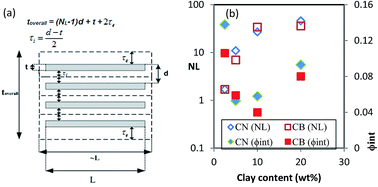
Ji's three-phase model considering the role of interphase region has been used frequently in literature,41,42 however, it appears to be useful for fully exfoliated system. In this study, a model is offered for the interphase region of a silicate layer in a stack, as shown schematically in Fig. 7a. According to this model, interphase region is divided into two parts including the internal interphase located between the gallery, and external interphase formed on the external surface of a stack. Due to the space limitation, the thickness of the internal interphase region (τi) is limited to the gap between two adjacent layers. The thickness of external interphase (τe) is different than τi and depends on the radius of gyration of macromolecules which was considered to be 10 nm in this study.41 Therefore, the total volume fraction of interphase region in the composite (ϕint) is the sum up the internal (ϕint,i) and external (ϕint,e) volume fractions. According to Fig. 7a, ϕint is directly related to the actual volume fraction of clay as where d is the d-spacing obtained by XRD for intercalated state, t the thickness of single silicate layer which is ∼1 nm and NL is the average number of silicate layer in a stack. Therefore, effective reinforcing particle (ERP) with uniform properties consisting of silicate layer and interphase regions is proposed to be used in the Halpin–Tsai model, as was performed in our previous work.43 The effective modulus (Eeff) of ERP which may be obtained by the rule of mixtures is expressed as:
![]() | (4) |
In order to employ the concept of ERP in Halpin–Tsai equation, the Eint and the average number of silicate layer (NL) must be known. The value of Eint was set to be 20 GPa which is consistent with literature.41 Fig. 7b exhibits the variation of NL and interphase volume fraction (ϕint) versus the clay loadings. At 2.5 wt% loading, NL is almost 2 for both CN and CB, indicating the nanodispersion of clays which is mainly the intercalated state, as shown in Fig. 2. Furthermore, the ϕint is considerably high at this clay content showing development of considerable interphase region. The thickness of gallery stack with two silicate layers is lower than gallery thickness observed by TEM (see Fig. 2), whereas overall thickness consisting of external interphase is calculated to be 22 nm which is almost consistent with microscopic observation. Moreover, it is observed that NL increases dramatically and ϕint decreases considerably by increasing the clay loading which could be a consequence of the limited dispersion state of clays.
This journal is © The Royal Society of Chemistry 2015 |