Sol–gel based simonkolleite nanopetals with SnO2 nanoparticles in graphite-like amorphous carbon as an efficient and reusable photocatalyst

Moumita Pal, Susanta Bera and Sunirmal Jana*
Sol-Gel Division, CSIR-Central Glass and Ceramic Research Institute (CSIR-CGCRI), 196 Raja S. C. Mullick Road, PO Jadavpur University, Kolkata 700032, India. E-mail: sjana@cgcri.res.in; janasunirmal@hotmail.com; Fax: +91 33 2473 0957; Tel: +91 33 23223303

Received 25th June 2015 , Accepted 19th August 2015

First published on 20th August 2015


Abstract

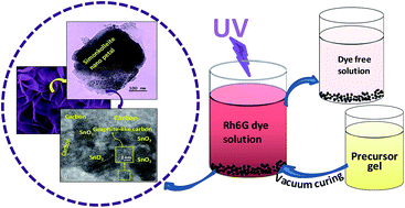
We report a new sol–gel nanocomposite (STC) having simonkolleite nanopetals (SC) and quasi-spherical tin oxide (SO) nanoparticles embedded in graphite-like amorphous carbon (C) as an efficient and reusable photocatalyst for the degradation of rhodamine 6G dye under UV (254 nm) illumination. The STC was synthesized using vacuum curing (450 °C) of precursor gel derived from a sol (Zn[thin space (1/6-em)]:[thin space (1/6-em)]Sn, 2[thin space (1/6-em)]:[thin space (1/6-em)]1) in 2-methoxyethanol with acetylacetone. The presence of tetragonal SO well decorated on rhombohedral SC forming nanoheterostructures in the carbon matrix was identified by X-ray diffraction, micro-Raman and X-ray photoelectron spectroscopy and electron microscopes (field emission scanning electron and transmission electron) studies. Carbon content and thermal weight loss behaviour in STC were studied by carbon determinator and thermogravimetry. The nanocomposite showed high photocatalytic activity (10−5 M dye solution degraded completely in 32 min). Reusability test of the photocatalyst exhibited about 95% of dye degradation after five successive recycles. In addition to accelerating photo-induced charge carrier separation and electron transport in the nanoheterostructures as revealed from electrochemical impedance spectroscopy response of the UV-exposed nanocomposite, an active role of the carbon at an optimum content (∼18%) was found for generating high BET specific surface area (∼143 m2 g−1). This simple synthesis strategy could open a new avenue to the development of sol–gel nanocomposites as efficient and reusable photocatalysts from various simonkolleite-based metal oxide semiconductors embedded in graphite-like amorphous carbon.


1. Introduction

Water pollution related to contamination by organic dyes is a serious global concern.1 In this regard, the synthetic wastewaters from different dye industries have posed a great threat to the water environment.2 The problem of this pollution could be mitigated cost effectively and economically by the use of nano metal oxide semiconductor (MOS) as photocatalyst under illumination of light.3 However, the fast recombination of photogenerated electrons and holes (charge carriers) could diminish the photocatalytic activity of the MOS.4 Thus, it is necessary to reduce the recombination rate of charge carriers that could enhance the lifetime of electrons and holes, resulting in an improvement of the activity of semiconductors.2 Accordingly, several strategies could be adopted. One could be an intentional creation of surface defects by incorporation of a suitable doping element into the host crystal lattice.5 The defects could act as trap states that reside within the band gap of the MOS. This strategy could result in the reduction of the recombination rate of charge carriers. In the same vein, the use of nanoheterostructures from mixed oxide semiconductors could also be regarded as an effective strategy.3,6 These heterostructures could be constructed of different metal oxide semiconductors (such as ZnO, SnO2, TiO2) with wide band-gap energy.6–9 Nowadays, these nanoheterostructures attract the attention of materials scientists due to their remarkable properties and several applications10 including photocatalysis. With respect to the activity, the large specific surface areas as well as unique spatial architectures of the heterostructures could make them highly efficient photocatalysts. One could improve the efficiency of the photocatalytic activity by reducing the recombination rate of photogenerated charge carriers and accelerating the reduction–oxidation reactions for degradation of organic pollutants (e.g. organic dyes).

It is worth noting11–13 that carbon (e.g. graphene, carbon nanotubes, amorphous carbon) could couple with several basic materials (such as oxides, metals, polymers) to improve their functional properties including their optoelectronic properties. Therefore, for the enhancement of the photocatalytic activity of a semiconductor, major work has already been reported on carbon (C)-coupled single metal oxide semiconductor (such as ZnO/C, SnO2/C, TiO2/C) nanocomposites.11–13 Also, very recently, carbon-coupled mixed metal oxide semiconductors (e.g. α-Fe2O3/Mn3O4/graphene), which showed excellent charge transfer performance towards photocatalytic water oxidation, have been reported.14 In these carbon-coupled nanocomposites, the photogenerated electrons would accumulate on the surface of the carbon to convert O2 to ˙O2 and the holes could remain on the semiconductor surface transforming H2O/OH to OH˙ for fast degradation of organics.15 In addition, the carbon could enhance the textural properties (particularly surface area and porosity) that could be necessary for effective contact with photodegradable organic dyes.

Simonkolleite (Zn5(OH)8Cl2·H2O, SC), synthesized mostly by hydrothermal, sonochemical and sol–gel processes, is known as a common corrosion product for zinc-bearing materials.16,17 It can also enhance the performance of photoelectrochemical cells.17 SC can be transformed into ZnO by thermal heating at relatively low temperatures.16 Moreover, SC is now recognized as one of the wide band gap semiconductors having electronic band structure similar to that of ZnO (bulk band gap energy of 3.3 eV).17 As a semiconductor, SC could also be able to decompose organic dyes (e.g. methyl orange). It is also known that the electrochemical/photochemical properties of SC could be improved by coupling with TiO2.18 This would form heterostructures, SC/TiO2. On the other hand, SnO2 is a well-known MOS having widespread applications (e.g. Li-ion batteries, gas sensing, photovoltaic conversion etc.).11 However, the photocatalytic activity of SnO2 is low.19 To the best of our knowledge, no report is yet available on carbon-coupled SC-based heterostructure semiconductor nanocomposites that would act as carbon-coupled mixed semiconductors. With this in mind, we considered SC/SnO2 as a new heterostructure system. In addition, due to the ability of carbon to couple easily with several materials, even with heterostructures, we attempted to synthesize in situ a nanocomposite of carbon-coupled SC/SnO2 heterostructures. In this system, it could be expected that the photogenerated electrons of SC would transfer to SnO2 as the electronic band structure of SC is similar to that of ZnO.17 This would result in a wide charge separation and consequently a reduction in the recombination rate of charge carriers. Moreover, the carbon in the nanocomposite could further enhance the photogenerated charge separation in the photo-responsive materials through acceleration of electron transport and improvement of the textural property that could be a favourable factor for enhancement of photocatalytic activity of the material towards degradation of organic dyes under light illumination.20 In this respect, we should mention that α-Fe2O3/Mn3O4/graphene composite has very recently been reported for photocatalytic water oxidation.14 That reported work is a motivation of the present work.

The sol–gel method is a facile technique, especially for the preparation of thin films and nanomaterials. In this technique, the properties of a material (such as microstructural, optical, electronic, optoelectronic properties) primarily depend upon several parameters such as precursor composition and chemistry, doping etc.5 Moreover, the curing treatments (e.g. vacuum curing, controlled-atmosphere curing) could also influence significantly the properties. This is because various chemisorption and desorption processes and oxygen diffusion mechanisms are highly involved during the curing treatments.5 Among the different curing treatments, vacuum curing could be a very important one, as carbon-based nanocomposite sol–gel materials for advanced applications could be developed from metal–organic precursors through this type of curing.21

Previously, we reported8,9 the change of crystallinity, morphology and microstructure and optical and photocatalytic properties of vacuum-cured ZnO–SnO2 thin films on glass from sols of varying Zn-to-Sn atomic ratio, R (1.86[thin space (1/6-em)]:[thin space (1/6-em)]1 to 2.33[thin space (1/6-em)]:[thin space (1/6-em)]1) or sol pH using zinc acetate dihydrate and tin chloride pentahydrate in 2-methoxyethanol with acetylacetone as a sol stabilizer. A detailed study8 was also performed on sol to gel formation, and chemical and physical properties of sols. However, adopting a particular synthesis process, the properties (morphological, optical, photocatalytic etc.) of a material in nano powder form would differ from those of a nanostructured thin film.22 Therefore, in the present work, a zinc–tin containing gel, derived from a precursor sol (Zn[thin space (1/6-em)]:[thin space (1/6-em)]Sn, 2[thin space (1/6-em)]:[thin space (1/6-em)]1), was cured systematically under the vacuum condition to obtain a nanocomposite powder. For the first time, in the nanocomposite, we found the formation of petal-like rhombohedral SC well decorated with tetragonal SnO2 nanoparticles embedded in graphite-like amorphous carbon, as confirmed by X-ray diffraction, micro-Raman spectroscopy, XPS, FESEM, TEM, etc. Moreover, the nanocomposite was mesoporous in nature, having a high specific surface area as studied by BET nitrogen adsorption–desorption isotherms. An excellent photocatalytic activity of the sample towards degradation of rhodamine 6G dye, considered to be a water pollutant, was observed under UV illumination (254 nm) (complete dye degradation in only 32 min). It was found that the presence of an optimum content (∼18%) of carbon in the nanocomposite enhanced the photocatalytic activity by over 6.5 times compared to SC/SnO2 nanoheterostructures. A reusability study with up to five successive recycles showed an excellent performance of the photocatalyst. In brief, this report presents for the first time a very simple strategy for the development of a carbon-coupled SC/SnO2 nanocomposite for efficient photocatalytic degradation of rhodamine 6G.

2. Experimental

2.1 Precursor sols

In this work, all the chemicals were used as received without further purification. The precursor sol (ZSS) for simonkolleite-tin oxide-carbon nanocomposite material (ZSV) was made by using zinc acetate dihydrate (ZA, Sigma-Aldrich, purity 98%; as a zinc source) and stannic chloride pentahydrate (TCP, Loba Chemie, purity 99.5%; as a tin oxide source) in 2-methoxyethanol (SRL, India, 99%) solvent with acetylacetone (acac) as sol stabilizing agent. In the precursor sol, the Zn to Sn (atomic) ratio was 2[thin space (1/6-em)]:[thin space (1/6-em)]1. The details of the preparation of the sol and its properties have already been reported in our previous work.8 In brief, for the preparation of the sol, the required quantities of ZA and TCP were dissolved in 2-methoxyethanol with acac. A sol (SS) was also prepared using TCP in 2-methoxyethanol in the presence of acac. In addition, another sol (ZS′S) was also made using ZA and TCP in 2-methoxyethanol without adding acac. Moreover, using zinc chloride (ZC, Sigma-Aldrich, purity 98%; as Zn source) in 2-methoxyethanol with acac, a different sol (Z′S) was also prepared. It is important to mention that the equivalent oxide weight percentage (wt%) and the molar ratio of acac with ZA or TCP (in the case of ZA-free sol) were kept fixed at 4.0 wt% and 1[thin space (1/6-em)]:[thin space (1/6-em)]1.4, respectively. Further, fixing oxide content (4%) and Zn to Sn molar ratio (2[thin space (1/6-em)]:[thin space (1/6-em)]1), two different sols were also prepared. These sols were named as ZSS-LC and ZSS-HC with molar ratio of acac to ZA of 1[thin space (1/6-em)]:[thin space (1/6-em)]1 and 1[thin space (1/6-em)]:[thin space (1/6-em)]2, respectively. Finally, the as-prepared transparent sols in Borosil glass beakers of 200/500 ml capacity were placed in a clean room (temperature, ∼30 °C; relative humidity, 50–55%) to obtain gels from the precursor sols. It is noted that the TCP-containing sols showed shorter gelling time than ZA- or ZC-based sols. This could be related to the different rate of hydrolysis of the salts.8,23

2.2 Nanocomposites

All the gels (ZSG-LC, ZSG, ZSV-HC, ZS′G, ZG and SG) were cured under vacuum condition (−1 mbar pressure) at 450 ± 5 °C in an electrical vacuum furnace8 with a heating rate of 2°C min−1 and a soaking period of 1 h at the maximum temperature. The vacuum curing was performed to generate a carbon matrix21 in the cured samples (discussed later). Under the vacuum condition, the cooling process was continued to ∼250 °C with a cooling rate of 2 °C min−1. Then, the furnace was allowed to cool down automatically to room temperature (30 ± 5 °C) under the vacuum condition. It is important to note that the ZS′G vacuum-cured sample was further heat treated (rate, 2 °C min−1) at 400 °C in pure oxygen gas (flow rate, 2 l min−1) atmosphere for 1 h at the maximum curing temperature to remove the carbon from the sample. The final samples derived from ZSG-LC, ZSG, ZSV-HC, ZS′G, ZG and SG gels were termed as ZSV-LC, ZSV, ZSV-HC, ZS′V, ZV and SV, respectively. Moreover, the ZSG gel was also cured in an air atmosphere at 450 °C for 1 h duration without vacuum. This air-cured sample was designated as ZSA. More details about the samples are given in Table S1 (ESI).

We have already reported in our previous study8 on the formation of acetylacetonato complexes of metal ions (Zn2+/Sn4+) present in the sols. However, in this work, an FTIR spectral study (Fig. S1 and Table S2, ESI) of the precursor gels dried at 130 ± 5 °C for 2 h in an air oven suggested that acac/solvent was present as organics, chemically interacted with metal ions in the gels. These organics in the gels after curing under vacuum condition could generate a carbon matrix (Table S3). It is important to mention that the formation of different inorganic crystals (Fig. S2) was also observed under the vacuum condition depending upon the curing temperature. We proposed chemical equations (eqn (1)–(7), ESI) based on systematic FTIR and Raman spectral as well as X-ray diffraction, electron microscopy (field emission scanning electron and transmission electron) and X-ray photoelectron spectroscopy analyses (discussed in later sections) for different in situ-generated products (especially simonkolleite, zinc oxychloride, tin oxide, zinc oxide and graphite-like amorphous carbon) derived from zinc–tin-containing gels dried at 130 °C, cured at different conditions (vacuum/oxygen/air) and temperatures.

2.3 Characterizations

2.3.1 Materials characterizations. In the ZSV sample, the presence of crystalline phases was identified by an X-ray diffraction (XRD) study employing an X-ray diffractometer (Philips PW 1730 XRD unit) with nickel-filtered CuKα radiation source (wavelength, 1.5418 Å) in the diffraction angle (2θ) range 10° to 70°. Morphology and microstructure of the samples were analyzed by field emission scanning electron microscopy (FESEM and FESEM-EDS, Zeiss, SUPRA™ 35VP). Transmission electron microscopy (TEM) was employed to determine the particle shape and size, tentative metal content as well as crystalline phases of the samples using a Tecnai G2 30ST (FEI) electron microscope operating at 300 kV. Initially, the samples were dispersed in low boiling alcohol (such as ethanol) by ultrasonication for about 2 h and the dispersed samples were placed carefully onto a carbon-coated Cu grid (300 mesh). Simultaneous thermogravimetry, thermogravimetric-differential scanning calorimetry (TG-DSC) (Netzsch STA 449F3 STA449F3A-0584-M) was carried out for ZSV to determine the weight loss behaviour of the sample in air up to 1050 °C using alumina as reference. The rate of heating was maintained at 5.0 K min−1 during the TG-DSC run. Carbon content in the samples was analyzed by a carbon determinator (LECO, USA; model C600). The rate of heating was maintained at 5.0 K min−1 during the TG-DSC run. Raman spectra (frequency range, 2000–200 cm−1) of the composites were measured at room temperature by employing a micro-Raman spectrometer (Renishaw inVia Raman microscope) using an argon ion laser with incident wavelength of 514 nm as an excitation source. The presence of different elements and their chemical states in the representative ZSV sample was determined by employing an X-ray photoelectron spectrometer (XPS) in the energy range 200–1200 eV (PHI Versaprobe II scanning XPS microprobe surface analysis system) using Al-Kα X-rays (, 1486.6 eV; ΔE, 0.7 eV at room temperature). The pressure in the XPS analysis chamber was better than 5 × 10⁻¹⁰ mbar and the energy scale of the spectrometer was calibrated with pure Ag. Moreover, the position of the C 1s peak was taken as a standard (binding energy, 284.5 eV). The specific surface area and pore size of the samples were measured by BET nitrogen adsorption and desorption isotherm studies at liquid nitrogen temperature using a Quantachrome (Autosorb1) machine. All the samples were outgassed in a vacuum at suitable temperature for about 4 h prior to the measurement. Electrochemical impedance spectra (EIS) (Nyquist plots) of the samples (ZSV, ZS′V, ZSA, ZV and SV) under UV light (254 nm in a custom built stainless steel UV curing chamber; details given in the next section) were recorded in the frequency range 1–1000 kHz with an AC amplitude of 200 mV utilizing a Metrohm Autolab 3200N instrument. A fixed weight (5 mg) of sample (photocatalyst) was added into 2 ml of 2-methoxyethanol, and then the aliquot was ground initially for more than 10 min until a viscous paste was formed. Finally, the paste was deposited (area, 1 cm2) onto a FTO glass (Technistro; sheet resistance, 10 Ω per □) adopting a doctor blading technique. The deposited film electrode (area, 1 cm2) served as the working electrode. A platinum wire as counter electrode (CE) and Ag/AgCl/3 M KCl as reference electrode were also used in this measurement. Moreover, aqueous Na2SO4 (0.01 M) solution prepared by using sodium sulphate salt (Ranbaxy, India, 99%) and deionized water from Milli-Q (Millipore, 18 MΩ) was used as the electrolyte solution.
2.3.2 Measurement of photocatalytic activity. Photocatalytic activity of the samples towards decomposition of rhodamine 6G dye with an initial dye concentration of 10−5 M (Co) in double distilled water was examined under UV illumination (wavelength, 254 nm) in a custom built stainless steel UV curing chamber equipped with a lid and an arrangement of three equally spaced UV lamps (power of 8 W each). For each sample, a suspension was prepared by adding 50 mg of the catalyst into a 100 ml aqueous dye solution in the dark. At a specific time interval, ∼4 ml of the dye solution was taken out from the photocatalytic reaction vessel (150 ml Borosil glass beaker) exposed to the UV light and the solid catalyst was separated from the solution by centrifugation.5 After that the visible absorption spectrum of the solution was recorded to find out the remnant dye concentration (C) with the help of a calibration curve for the dye solutions. The calibration curve was constructed by plotting dye concentration against absorbance (OD) at 527 nm peak wavelength of the solutions obeying the Lambert–Beer law. The photocatalytic activity of the samples was analyzed by plotting ln(Co/C) (Co, initial dye concentration; C, remnant dye concentration) versus illumination time. The rate constants of the decomposition reaction (considering first-order reaction kinetics) were determined from the plots. All the details of the photocatalytic activity have already been reported elsewhere.5,8 It is noted that the photocatalytic activity of the representative ZSV sample was also investigated using specific chemicals (such as tert-butyl alcohol, potassium iodide, 1,4-benzoquinone) in the dye solution for understanding the possible mechanism governing the photocatalytic activity. Moreover, to investigate the recyclability of the photocatalyst, a reusability study of the ZSV photocatalyst for up to five successive recycles was performed (Fig. S3, Tables S4 and S5; ESI). After the 1st cycle, the catalyst was extracted by centrifugation and then washed thoroughly in deionized water. Subsequently, the recovered solid mass was washed with ethanol followed by drying at 80 °C for about 5 h in an air oven. The process was repeated for up to five successive recycles. The reusability study of the catalyst showed that there is a minor decrease (about 5%) in the dye decomposition (Table S5, ESI) after 5 successive recycles.

3. Results and discussion

3.1 Phase structure

Fig. 1 shows the XRD patterns of ZSV including ZS′V, ZV and SV samples. All the samples were found to be nanocrystalline in nature (Table S6, ESI) as confirmed from the measurement of crystallite sizes from the XRD patterns of the samples using Scherrer's equation.24 For ZSV, the XRD patterns (in terms of 2θ peaks) are fully matched with two different types of crystals: rhombohedral simonkolleite (r-SC) [JCPDS Card 07-0155] and tetragonal SnO2 (t-SnO2) [JCPDS Card 41-1445]. However, no trace of hexagonal ZnO (h-ZnO) was detected in ZSV while in ZV the presence of both r-SC and h-ZnO was identified (inset, Fig. 1). It is interesting to note that in zinc–tin-containing precursor gels (ZSG or ZS′G), the formation and stability of r-SC greatly depend upon the gel curing temperature (T) and atmosphere. However, the change of curing condition did not affect the formation of t-SnO2. It was also seen that under vacuum curing of ZSG precursor gel at 400 °C, r-SC started to form (Fig. S2, ESI), but at a curing temperature of 450 °C, the sample was enriched with r-SC in addition to t-SnO2. Anyhow, on further increasing T to 500 °C, the XRD patterns of SC disappeared and several new peaks were noticed distinctly. It is noted that the peaks were fully matched with h-ZnO [JCPDS card 36-1451]. On the other hand, for the ZSG gel when cured at 450 °C under an air atmosphere, orthorhombic zinc oxychloride (o-ZnO·ZnCl2·H2O, o-ZOC) [JCPDS card 45-0819] along with t-SnO2 was identified but no trace of r-SC was found from the XRD patterns of the ZSA sample. Moreover, the ZS′V sample prepared by two-step curing of ZS′G gel derived from ZSS equivalent sol composition without adding acac also showed the formation of o-ZOC with the presence of a noticeable amount of r-SC. Here, the two-step curing means that the ZS′G gel was initially cured under vacuum at 450 °C and further cured at 300 °C in pure oxygen gas atmosphere for 2 h for removal of carbon (details discussed later under Raman spectral study, Fig. 2). Hence, the XRD study revealed that during thermal curing of zinc–tin-containing precursor gels (ZSG/ZS′G), the air/oxygen atmosphere is not suitable for the formation of r-SC, and the most favourable condition for r-SC formation is vacuum curing at a temperature of 450 °C. On the other hand, the ZV and SV composites showed the presence of r-SC with small content of h-ZnO and t-SnO2, respectively, as evident from their XRD patterns (Fig. 1). As reported by many authors,17,18,25–27 the formation of r-SC mainly depends on precursor sol/solution pH and temperature in rather complicated processes including hydrothermal, co-precipitation, electrochemical etc. In this respect, the present preparation method of r-SC could certainly be a novel process. However, the exact role of vacuum curing in the formation of r-SC has yet to be investigated. Further, the FTIR spectral study (Fig. S1, Table S2) evidenced that the organics are present in the precursor gels even after thermal baking at 130 °C. This could be an obvious observation of the sol–gel process.28 Moreover, under vacuum curing of the gels, the formation of amorphous/crystalline carbon21,29,30 could be expected in the sample (details discussed later under Raman, XPS and TEM analyses). However, no characteristic XRD patterns for crystalline carbon were identified for the vacuum-cured samples. This would indicate the formation of amorphous carbon; otherwise, if the generated carbon is crystalline, its characteristic peaks would be overlapped with the XRD peaks of t-SnO2/r-SC crystals. Sometimes, due to high dispersion14 of carbon, the sample would also not be amenable to XRD measurement.
image file: c5ra12322d-f1.tif
Fig. 1 XRD patterns of ZSV, ZS′V, ZSA, ZV (inset) and SV samples.

image file: c5ra12322d-f2.tif
Fig. 2 Raman spectra of ZSV nanocomposite along with those of ZS′V, ZSA, ZV and SV samples. Inset shows the Raman spectrum of ZS′V sample cured at 450 °C under vacuum.

3.2 Raman spectra

Raman spectroscopy is an efficient tool for the characterization of carbon materials.31–35 Two distinct Raman peaks located at ∼1595 cm−1 and ∼1355 cm−1, assigned to ‘G’ (graphene) and ‘D’ (defect) bands of carbon,14,31–35 were observed in the spectra of ZSV, ZV and SV (Fig. 2) as well as in those of ZSV-LC and ZSV-HC (Fig. S4) samples prepared by curing the precursor gels under vacuum at 450 °C. However, when the gels were cured in air or pure oxygen atmosphere (in the case of ZS′V and ZSA samples), the Raman vibrations were not observed. It is important to note that the ZS′V sample was prepared by a two-step curing process (initially cured under vacuum at 450 °C and finally cured again at 300 °C in pure oxygen gas atmosphere for 2 h) from ZS′G gel derived from ZSS equivalent sol composition without adding acac. Also, the Raman spectrum (inset, Fig. 2) of 450 °C vacuum-cured ZS′V sample showed the presence of carbon as evident from the observation of Raman peaks at ∼1595 cm−1 and ∼1355 cm−1, corresponding to ‘G’ and ‘D’ bands of carbon. Generally, the G band represents the vibration of sp2C in graphitic32 domain while the D band evidences sp3C or disordered carbon structure.14,33 In the present work, the observed G band position is relatively higher than that of graphene.32 It is known that the G band position would depend upon the sp3C/sp2C fraction in carbon material.34 With an increase in the fraction of sp3C, the in-plane correlation length of graphitic layers would reduce and as a consequence the average G band position moves towards higher energy region.35 This might be caused by the shortening of interplanar distance, d002 (ref. 29) (discussed under TEM analysis, Fig. 5). Therefore, the Raman spectral analysis suggested that the carbon present in the vacuum-cured samples could be graphite-like amorphous carbon. This amorphous carbon in the SC/SnO2 composite could be useful for improving photocatalytic activity towards degradation of organic dye36 (discussed later). Also, we measured the content of carbon in ZSV-LC, ZSV, ZSV-HC, ZV and SV samples by a carbon determinator and the content of carbon measured was ∼10%, ∼18%, ∼23.5%, ∼6.5% and ∼17%, respectively (Table S3, ESI). The lowest content of carbon in ZV could be because of non-formation of zinc–acetylacetonato complex in the precursor gel derived from the sol using ZnCl2 as zinc source. This was verified from FTIR spectra (Fig. S1 and Table S2, ESI) of ZG gel baked at 130 °C.

3.3 XPS analysis

In the ZSV sample, the presence of SC and SnO2 semiconductors along with graphite-like amorphous carbon was evidenced from XRD structural (Fig. 1) and Raman spectral (Fig. 2) analyses. Mainly two different hybridizations, sp2C and sp3C, could be expected in amorphous carbon.32 However, the determination of relative content of sp2C and sp3C in the carbon was not possible from the Raman study (Fig. 2). Therefore, XPS analysis (Fig. 3) of the sample was absolutely necessary to know the relative content of each type of carbon. In addition, the presence of different elements with their chemical states was also essential for the purpose of the Raman study. The existence of non-metallic elements such as carbon, chlorine and oxygen as well as metallic elements such as zinc and tin was identified from their corresponding binding energy signals in the XPS survey spectrum (Fig. 3a) of the sample. The sources of carbon, chlorine and oxygen could be the graphite-like amorphous carbon, SC and SC/SnO2, respectively, as evident from Raman (Fig. 2) and XRD (Fig. 1) studies of the sample. In the case of carbon, a broad asymmetrical signal of C 1s core level could be decomposed into two Gaussian-fitted components with binding energy peaks located at 284.1 ± 0.1 eV and 285.9 ± 0.2 eV, assigned to sp2C and sp3C carbons, respectively (Fig. 3b). From the peak area of the signals, the calculated relative contents of the sp2C and sp3C carbons are ∼55.5% and ∼44.5%, respectively. Thus, the XPS data strongly supported the Raman spectral study (Fig. 2) related to the existence of graphite-like amorphous carbon.35 Another broad signal appeared with a peak energy of ∼530 eV for O 1s that could be split into two distinct Gaussian-fitted peaks (Fig. 3c) located at 530.1 ± 0.1 eV (S1) and 531.6 ± 0.2 eV (S2). The values of the peaks for O 1s matched with the data reported by Chen et al.37 The S1 signal could relate to O2− ions37 of SC and SnO2 as evident from XRD (Fig. 1) and Raman spectra (Fig. 2) while the S2 signal could be assigned to O2− ions of oxygen-deficient semiconductors (SC, SnO2).5 On the other hand, the binding energy peaks of Zn 2p1/2 and Zn 2p3/2 core levels (Fig. 3d) were observed at 1044.8 ± 0.2 eV and 1021.7 ± 0.1 eV, respectively. The energy difference between the two core levels is 23.1 ± 0.1 eV, matching well with the reported value for Zn2+.5,38 The XPS spectrum of the sample showed triplet signals of Sn 3d (Fig. 3e). The triplet signals with decreased peak intensity appearing at 486.4 ± 0.2, 494.9 ± 0.1 and 499.3 ± 0.2 eV could originate from the core levels of Sn 3d5/2, Sn 3d3/2 and Sn 3d1/2, respectively.38,39 The binding energy difference of Sn 3d5/2 and Sn 3d3/2 core levels (Δ) is 8.4 eV. In this respect, Shi et al.38 also reported a similar value of Δ. It is known that in Sn 3d5/2, the binding energies of Sn4+ (486.5 eV) and Sn2+ (486.25 eV) are very close.40 Therefore, it is difficult to separate Sn2+ from Sn4+ in the XPS data. However, the presence of tetragonal SnO2 from the XRD pattern (Fig. 1) of the sample could emphasize the existence Sn4+. Further, the XPS signal for Sn0 could appear at relatively low energy (484.6 eV)41 compared to the energy of the signal for Sn4+/Sn2+. In fact, it was not detected from the XPS measurement. Hence, the possibility of Sn0 formation in the sample could be discounted.
image file: c5ra12322d-f3.tif
Fig. 3 XPS results of ZSV nanocomposite. (a) Survey spectrum shows the presence of different elements; (b) typical XPS data for the binding energy of C 1s; (c) binding energy signal for O 1s; binding energy signals for core levels of (d) Zn 2p and (e) Sn 3d.

3.4 Morphology and microstructure

3.4.1 FESEM study. Fig. 4 and S5 (ESI) display the FESEM results of ZSV, ZV and ZSA along with ZS′V and SV samples. The FESEM images (Fig. 4a and b) of the ZSV sample clearly show particles with petal-like hierarchical structures (petal thickness, 28–41 nm; inset, Fig. 4b) together with quasi-spherical particles (average size, 15 ± 3 nm) embedded in a featureless matrix (inset, Fig. 4a). The featureless matrix is believed to be graphite-like amorphous carbon (more discussion under TEM analysis, Fig. 5). It is worth noting that Raman spectral (Fig. 2) and XPS (Fig. 3) analyses already evidenced the presence of carbon in ZSV, ZV and SV samples. Further, the results of FESEM-EDS study (Fig. 4b1) of the composition (atomic percentage, at%) of Zn and Cl of the hierarchical microstructures are given in Fig. 4b which shows about 67.3% Zn and 32.7% Cl (Zn to Cl atomic ratio, RZC = 2.06). The source of Zn and Cl could be the SC nanopetals as evident from XRD patterns (Fig. 1) of the ZSV sample. It is interesting to note that the ZSA sample (obtained from ZSG gel after curing at 450 °C under air atmosphere) shows spherical clusters (size, 20 ± 5 nm) (Fig. 4c and inset). These clusters could be mixtures of tetragonal-SnO2 and orthorhombic zinc oxychloride as confirmed from the XRD patterns (Fig. 1) of the sample. On the other hand, the FESEM microstructure (Fig. 4d) of ZV displays the presence of nanopetal/plate-like particles (thickness, 23–30 nm) that could be of r-SC/h-ZnO as evident from the XRD patterns (inset, Fig. 1) of the sample. The RZC value calculated from the FESEM-EDS curve (Fig. 4d1) of the microstructure (Fig. 4d) could be comparable with the RZC value of ZSV. This result implies that the ZV sample also contains SC as identified from its XRD curve (Fig. 1). It is worth noting that flower-like morphology constructed of hexagonal plates (Fig. S5a, ESI) was found in the ZS′V sample by curing initially at 450 °C under vacuum and finally at 300 °C in pure oxygen of ZS′G gel that was prepared from the precursor sol without using acac. Therefore, it could be that the formation of petal-like morphology of SC is possible in the sample derived from the precursor sol with acac. Although the exact role of acac in the formation of SC is not known, the graphite-like amorphous carbon generated in situ in the nanocomposite would help to form the morphology.44 It should be mentioned that the SV sample consisting of t-SnO2 (Fig. 1) shows only spherical nanoclusters (size, 17 ± 2 nm) as revealed from the FESEM study (Fig. S5b, ESI).
image file: c5ra12322d-f4.tif
Fig. 4 FESEM images of (a and b) ZSV, (c) ZSA and (d) ZV samples along with FESEM-EDS curves of (b1) and (d1) obtained from the microstructures (b) and (d), respectively. Zone (i) of (a) is magnified in (b) showing petal-like particles, while zone (ii) of the enlarged part of image (a) displays quasi-spherical nanoparticles embedded in a featureless matrix.

image file: c5ra12322d-f5.tif
Fig. 5 TEM results of ZSV sample. (a) TEM image shows a petal-shaped large particle decorated with nanoparticles embedded in a featureless matrix. A magnified marked portion of (a) is shown as (b) (inset shows the histogram for particle size distribution with average particle size of 10.5 nm). In (b), the HRTEM image of a particle (marked as A) is also given. The HRTEM image shows distinct lattice fringes with d spacing matched with t-SnO2 along the (110) plane. The SAED of the microstructure (a) is displayed as (c), confirming the presence of both t-SnO2 and o-SC nanocrystals. TEM-EDS of the microstructure (a) is shown in (d). The presence of different elements such as Zn, Sn, Cl, O, C etc. is detected from the EDS curve with contents of Zn (∼66.2%), Cl (∼26.4%) and Sn (∼7.4%). The sample also shows a different microstructure as shown in (e). (f) Magnified part (marked as square) of (e), confirming the presence of both t-SnO2 (from the lattice fringes) and graphite-like amorphous carbon matrix.

Simonkolleite is an important mineral with a complex structure of a transition metal (Zn) layered hydroxide chloride.27 It usually exists as hexagonal sheets.17 Sometimes, depending upon the synthesis parameters, the formation of hierarchical structures could be possible.26,27 However, no distinct mechanism for the formation of such hierarchical structures is available in the literature. Mahmoudian et al.27 electrodeposited SC flower-like nanostructure on porous surface of zinc, coated with poly(N-methylpyrrole). The authors considered that the trapping of Cl and OH ions within the pores of coatings could be the reason for the morphology. In the present work, the formation of petal-like hierarchical structure of SC could be due to the curing of the precursor gels under vacuum. This is because various chemisorption and desorption processes as well as oxygen diffusion mechanisms are greatly involved during the curing process.8

3.4.2 TEM study. Fig. 5 displays the field emission transmission electron microscopy characterization result of the ZSV nanocomposite. The TEM image of the sample shows a flower-like hierarchical microstructure (Fig. 5a) decorated well with SnO2 nanoparticles (average size, ∼16 nm; histogram, inset of Fig. 5b). The HRTEM image (inset A, Fig. 5b) of a nanoparticle (marked A) shows distinct lattice fringes with interplanar distance d (0.33 nm) matched with tetragonal SnO2 nanocrystals [JCPDS card 41-1445]. This observation fully supported the XRD result (Fig. 1) of the sample. The SAED pattern (Fig. 5c) for the microstructure as displayed in Fig. 5a shows several bright spots and the calculated d values from the spots corresponded to orthorhombic SC and tetragonal SnO2 nanocrystals. The TEM-EDS (Fig. 5d) compositional (atomic percentage, at%) analysis for Zn, Sn and Cl elements for the hierarchical microstructure as displayed in Fig. 5a shows the presence of about 56.7% Zn, 27.2% Cl and 16.1% Sn with a Zn to Cl ratio (RZC) of 2.08. It is worth mentioning that a similar RZC value for the petal-like microstructure was obtained by the FESEM-EDS analysis (Fig. 4b1). Moreover, a typical TEM image (Fig. 5e) at higher magnification of the ZSV sample shows the nanoparticles are embedded intimately in a matrix. The HRTEM image (Fig. 5f) of the area marked by the square in Fig. 5e confirms the presence of distinct lattice fringes with interplanar distance d (0.33 nm) matched with tetragonal SnO2 nanocrystals [JCPDS card 41-1445] embedded in a mesoporous milky diffraction background. This background could suggest the presence of carbon45 in the nanocomposite. It is also noted that in several parts of the matrix, the signature of graphitic layers29 with shorter interplanar distance (0.29 nm) than graphene46 is observed. The shortening of interplanar distance could be considered as a consequence of the vacuum curing of precursor gels. Therefore, in the present work, the existing carbon matrix in the sample could be termed as graphite-like amorphous carbon which is found to have a somewhat disordered structure.29 It should be mentioned that the presence of carbon in the ZSV nanocomposite has already been confirmed by Raman (Fig. 2) and XPS (Fig. 3) analyses.

3.5 TG-DSC study

The thermal stability in terms of thermal weight loss behaviour of the ZSV sample having graphite-like amorphous carbon (Fig. 2, 3 and 5) was investigated by TG-DSC analysis (Fig. 6). The DSC curve shows two endothermic peaks appearing below 200 °C with the corresponding weight loss of about 4% as measured from the TG curve. This weight loss could be attributed to the loss of adsorbed water.42,43 It is also seen from the DSC curve that the pyrolysis (exothermic) reaction starts at ∼350 °C and ends at ∼530 °C. From the TG curve, up to ∼530 °C, there is a total weight loss of 23.1%, but above 530 °C, no further weight loss was measured from the sample. Hence, considering the loss of water, the further loss of about 19% could be ascribed to the loss of carbon along with the weight loss accompanying the conversion of SC [Zn5(OH)8Cl2·H2O] to ZnO as evidenced from the XRD (Fig. S2) study. It is worth mentioning that the presence of carbon in the sample was already confirmed from the Raman, XPS and HRTEM analyses (Fig. 2, 3 and 5). Moreover, about 18% of carbon in the sample was measured by the carbon determinator (Table S3). Therefore, in the sample, the amount of carbon obtained from the TG-DSC analysis (Fig. 6) is approximately matched with the data from the carbon determinator.
image file: c5ra12322d-f6.tif
Fig. 6 TG-DSC curves of ZSV sample.

3.6 Textural properties

Textural properties (surface area, pore size) of ZSV (Fig. 7a) and ZS′V (Fig. 7b) nanocomposites were measured using the BET nitrogen adsorption–desorption method. The isotherms of both the nanocomposites conform to IUPAC type IV architecture having H3 hysteresis loop, indicating the presence of slit-like mesopores in the samples.47 The pore size distribution curves were plotted from the desorption branch of the isotherms (insets of Fig. 7a and b). From the distribution curves, the calculated average pore sizes were 3.1 nm and 3.5 nm for ZSV and ZS′V, respectively. It is worth noting that a very high BET specific surface area of 142.6 ± 0.2 m2 g−1 was obtained from the isotherms of the ZSV sample. The presence of graphite-like carbon29 as evidenced from Raman spectral (Fig. 2), TEM microstructural (Fig. 5) and XPS (Fig. 3) analyses of the sample could be the reason for the high surface area. This is true because in the absence of carbon (Fig. 2) in the ZS′V sample, the measured surface area was more than 4.5 times lower (31.6 ± 0.2 m2 g−1) than for ZSV. Due to this large surface area in ZSV, the surface active sites could increase and this typical textural property of the nanocomposite could be beneficial for obtaining a high photocatalytic activity towards degradation of organic dye under light illumination (discussed later).
image file: c5ra12322d-f7.tif
Fig. 7 BET nitrogen adsorption and desorption isotherms of (a) ZSV and (b) ZS′V nanocomposites (insets show the pore size distribution curves constructed from the desorption branch of the isotherms).

3.7 Photocatalytic activity

Photodecomposition (Fig. 8a and b and Table S4 of ESI) of rhodamine 6G dye (10−5 M aqueous solution) using the ZSV nanocomposite as photocatalyst was performed under UV illumination (wavelength of 254 nm) after keeping the dye solution in the presence of the sample for an optimum time of 30 min to attain dye adsorption equilibrium under dark condition (see Fig. S6, ESI for details). It was seen that the dye in the water solution decomposed completely in 32 min of the UV exposure. We also determined the dye decomposition rate constant, k, by plotting ln(Co/C) versus time, considering first-order reaction kinetics. Here, Co is the initial concentration and C denotes the remnant dye concentration at different times of UV exposure. All the plots are found to be approximately linear, implying pseudo first-order reaction kinetics of the dye degradation. Using the ZSV sample having graphite-like amorphous carbon, we obtained a k value of 0.096 min−1 (inset, Fig. 8b). It is worth noting that the carbon-free nanocomposite, ZS′V, having SC and SnO2 nanoheterostructures in the presence of non-semiconductor zinc oxychloride as evident from XRD (Fig. 1) and Raman spectral results (Fig. 2), showed a nearly seven times lower k value (0.0145 min−1) (inset, Fig. 8c) compared to the k value of ZSV. Also, other samples (ZSA, ZV and SV) showed very low rate constants (0.001–0.0045 min−1) (insets, Fig. 8d, S7a and b and Table S4, ESI). Therefore, for this synthesis process, the single metal oxide nanosemiconductor coupled with graphite-like amorphous carbon in ZV and SV samples or the carbon-free SC/SnO2 nanoheterostructures showed very negligible photocatalytic activity; although the crystallite (Table S6)/particle sizes (Fig. 4, 5 and S4, ESI) of SC and SnO2 in all the samples were in the nano domain which could mean the possibility of forming photogenerated charges (electrons and holes) with stronger oxidative/reductive capabilities. In this work, the presence of carbon in the mesoporous (average pore size, 3.1 nm) ZSV nanocomposite with large specific surface area (142.6 ± 0.2 m2 g−1, measured by BET nitrogen adsorption–desorption isotherms, Fig. 7a) could help to create a larger number of contacts with the dye molecules on the catalyst surface.36 Moreover, the carbon could possibly improve the separation efficiency of photogenerated charge carriers via interfacial interactions with the nanoheterostructures (see Fig. 9 for more details). This could lead to an improvement of photocatalytic activity of the ZSV nanocomposite towards degradation of an organic pollutant like rhodamine 6G under UV illumination. Moreover, the reusability test (Fig. S3 and Table S5) of the ZSV photocatalyst shows only a 5% decrease in the dye decomposition efficiency after five successive recycles for 32 min of UV exposure in each cycle. The slight decrease of the photocatalytic activity of ZSV could be attributed to oxidation of the carbon by energetic valence band holes (h+) generated in the photochemical reaction. However, the oxidation process seemed to be very slow and the high concentration of the dye could greatly compete with the hole scavenging process.48 It is also true that the photocatalytic activity could be reduced due to photocorrosion of nanosemiconductors (SC and SnO2). However, the presence of graphite-like amorphous carbon would inhibit the photocorrosion effectively.48 In this respect, the ZSV sample as a new sol–gel nanocomposite was better with few exceptions (Table S7, ESI) than other photocatalysts reported in the literature.49–53 Therefore, the ZSV nanocomposite could be considered as a new, cost effective and highly efficient photocatalyst towards degradation of organic pollutants like rhodamine 6G dye under UV illumination.
image file: c5ra12322d-f8.tif
Fig. 8 Photocatalytic activity of ZSV, ZS′V and ZSA samples towards degradation of rhodamine 6G dye under UV illumination. (a) Remnant dye concentration versus UV exposure time. (b–d) Visible spectra of dye solution at different illumination times for the photocatalysts ZSV, ZS′V and ZSA, respectively (insets show respective dye decomposition rate constant, considering first-order reaction kinetics).

image file: c5ra12322d-f9.tif
Fig. 9 Electrochemical impedance (EIS) Nyquist plots of electrodes of different samples obtained under UV (254 nm) illumination.

It is known48,54–60 that charge carrier (electron and hole) separation and electron transport behaviours of semiconductors are critical factors in photocatalytic dye decomposition reactions. These behaviours could clearly be understood from a study using the powerful tool of electrochemical impedance spectroscopy (EIS). In this respect, the smaller arc radius in the EIS semicircle of an electrode (photocatalyst) under suitable light irradiation could indicate an effective separation of photogenerated electron–hole pairs as well as fast interfacial charge transfer. Moreover, the presence of one arc/semicircle on the EIS plane implies an involvement of only surface charge-transfer step in the photocatalytic reaction and the magnitude of the arc radius could be related to the rate of the degradation reaction. Therefore, several authors48,54–60 efficiently utilized EIS to explain the photocatalytic activity of semiconductors including carbon-coupled single/mixed metal oxide nanocomposites (see text with Table S8 of ESI for more details). In the present work, EIS was performed on the ZSV nanocomposite as well as on other samples (ZS′V, ZSA, ZV and SV) to understand the difference in charge separation behaviour which could directly relate to the photocatalytic activities towards degradation of rhodamine 6G dye as observed under UV illumination (Table S4 and Fig. S7, ESI). The EIS Nyquist plots of UV-illuminated (254 nm) photoelectrodes are displayed in Fig. 9. The plots of the samples each show only one arc/semicircle on the EIS plane, indicating only the surface charge-transfer could occur in the electrodes.20,48 Moreover, the radius (r) of the arc/semicircle in the Nyquist plots for the ZSV, ZS′V, ZSA, ZV and SV photoelectrodes decreases in the order rSV > rZV > rZSA > rZS′V > rZSV. A similar trend was also observed for the change of magnitude of the arc/semicircle for the samples under dark condition (not shown here). This result obviously implies that the most effective photogenerated charge separation/reduction of the recombination rate of the charges occurred for ZSV.48 It could also indicate that the fastest interfacial charge transfer to acceptor/donor could occur for the ZSV sample where the graphite-like amorphous carbon is present as evident from the Raman spectral (Fig. 2), XPS (Fig. 3), carbon content (Table S3, ESI) and TEM (Fig. 5) analyses of the sample. This phenomenon could be possible via an interfacial interaction between the carbon and the nanoheterostructures made by SC nanopetals and SnO2 nanoparticles. This assumption could be justified from the experimental observation of much higher arc radius (in the EIS plot) for ZSV as compared to that for the carbon-free ZS′V sample (confirmed by Raman spectral study, Fig. 2). It is worth noting that both samples possessed SC nanopetals/nano SnO2 nanoheterostructures. It is also important to mention that the change in magnitude of the arc/semicircle in the Nyquist plots of the samples was consistent with the photocatalytic activities in terms of the dye degradation rate constant (k) under UV illumination. This improved electrochemical property of the ZSV nanocomposite in terms of the photocatalytic activity would rely on the electron transport properties of graphite-like amorphous carbon.20 It has already been reported by many authors that relatively higher photocatalytic efficiency could be obtained in nanoheterostructure semiconductors (like SC/TiO2, ZnO/SnO2, ZnO/TiO2 etc.).18,61,62 Therefore, in the present work, this implies that the carbon that is strongly coupled with the SC petals and SnO2 nanoheterostructures in the ZSV sample could further improve the photocatalytic efficiency and make the nanocomposite a highly efficient photocatalyst towards degradation of the dye. In this respect, the higher specific surface area of the ZSV sample as measured by BET nitrogen adsorption–desorption isotherms (Fig. 7) due to presence of the carbon was also a beneficial factor for the improvement of the photocatalytic activity.11 In the same vein, due to its large surface area, the surface active sites in the photocatalyst could consequently increase, and more and more dye molecules could come into contact with the surface of the catalyst.48,63 As a result, an effective photocatalytic reaction could occur for the ZSV sample. In this respect, many authors have already reported the effect of surface area on the photocatalytic activity (rate constant) of different photocatalysts including carbon-based composite semiconductor materials on different organics (see details in Table S9 and 10 of ESI).

It is worth noting11–13 that carbon (e.g. graphene, carbon nanotubes, amorphous carbon) could couple with several basic materials (such as oxides, metals, polymers) and even with heterostructures to improve the functional properties including optoelectronic properties of materials. In this regard, major studies have already been done on carbon-coupled single metal oxide semiconductor composites (such as ZnO/C, SnO2/C, TiO2/C) for enhancing the photocatalytic activity of semiconductors.11–13 Also, carbon-coupled mixed metal oxide semiconductors (e.g. α-Fe2O3/Mn3O4/graphene) showed excellent charge transfer performance for photocatalytic water oxidation.14 It is also known that in the carbon-coupled nanocomposites, the photogenerated electrons would accumulate on the carbon surface to convert O2 to ˙O2 and the holes could remain on the semiconductor surface, transforming H2O or OH to OH˙, useful for fast degradation of organic dyes by the generated free radicals.15,64 Also, the carbon could enhance the textural properties (particularly surface area and porosity) that could be necessary for effective contact of photodegradable organic dyes on the surface of photocatalysts. Therefore, in the present work, a dual role of the carbon was found: one role involving faster rate of interfacial charge transfer and another involving enhancing the specific surface area of the ZSV nanocomposite. On the other hand, SC is now recognized as one of the wide band gap semiconductors having electronic band structure similar to that of ZnO (bulk band gap energy of 3.3 eV).17 Moreover, it could be able to decompose organic dyes. It is also known that the electrochemical/photochemical properties of SC could be improved by coupling with TiO2 (ref. 18) as heterostructures. SnO2 is a well-known metal oxide semiconductor having widespread applications.11 However, the photocatalytic activity of SnO2 is low.19 From the results of this work, it could be expected that the photogenerated electrons of SC would transfer to SnO2 as the electronic band structure of SC is similar to that of ZnO.17 This would result in a wide charge separation and a consequent reduction in the recombination rate of charge carriers. Moreover, the carbon in the nanocomposite could further enhance the photogenerated charge separation in the photo-responsive materials through accelerating electron transport in addition to improving the textural properties (such as surface area, porosity) that could be a favourable factor for enhancing active sites of the photocatalyst under UV illumination.20 In this respect, we should mention that an α-Fe2O3/Mn3O4/graphene composite was reported very recently as a highly efficient photocatalyst for water oxidation.14

It is known that an optimum content of carbon could be required for obtaining efficient photocatalytic activity in carbon-coupled photocatalysts for decomposition of water pollutants (such as organic dyes).65,66 Therefore, it is absolutely necessary to verify whether ∼18% graphite-like amorphous carbon that is present in ZSV could be an optimum content of carbon for this purpose. In this respect, we changed the carbon content in the nanocomposites by varying the acac content in the two precursor sols and obtained ∼10% and 23.5% carbon (Table S3, ESI) as analyzed by carbon determinator in ZSV-LC and ZSV-HC, respectively. It was found that ZSV-LC showed a lower value of first-order rate constant (k = 0.043 min−1; ∼100% dye decomposition in 64 min) than ZSV for dye decomposition (Fig. S8, ESI) under UV exposure. However, an interesting result was obtained for the ZSV-HC sample. It is noted that by keeping the ZSV-HC sample continuously stirred in the dye solution for 64 min under the dark condition, a complete adsorption of the dye was seen (Fig. S8, ESI). This strong adsorption capability but low photocatalytic dye decomposition activity (∼57% dye decomposed in 60 min under UV illumination) of ZSV-HC compared to the ZSV-LC and ZSV samples is discussed in detail in the ESI (Fig. S8). Hence, it is clear that the ZSV-HC sample was an efficient dye adsorbent but not an efficient photocatalyst. This adsorption capability of ZSV-HC could be ascribed to the presence of excess content of carbon. Possibly, this excess carbon could create a shielding effect of the incident UV light65,66 and covered the active sites of the nanoheterostructures (SC nanopetals/quasi-spherical tin oxide nanoparticles) in the nanocomposite. In the case of ZSV-LC, the lowest carbon content would not be sufficient for charge separation and consequent reduction in the recombination rate of photogenerated charge carriers (electrons and holes).59,67 Therefore, an optimum carbon content of ∼18% (Table S3) in the ZSV sample could be required for maximizing the photocatalytic activity towards decomposition of rhodamine 6G dye under UV exposure.

It is known that several reactive species (RES) could be produced during photocatalytic dye decomposition reactions.64 Their generation could be understood by the use of specific RES scavengers (such as tert-butyl alcohol, TBA; potassium iodide, KI; and 1,4-benzoquinone, BQ). Therefore, many authors have used TBA, KI and BQ in dye solutions to examine the formation of ˙OH (hydroxyl radical), h+ (hole) and ˙O2 (superoxide radical), respectively. In our present work, we also used these scavengers for the purpose of understanding the existence of specific RES that took part in the dye decomposition reaction. As can be seen from Fig. S9 (ESI), 1 mM BQ solution could completely terminate the dye degradation reaction by consuming/arresting ˙O2 radicals that play a significant role in the photocatalytic reaction. Moreover, on addition of 10 mM TBA/2 mM KI solution, the dye degradation was also found to decrease significantly. Therefore, the RES scavenger experiment clearly indicated that ˙O2 and ˙OH radicals as well as h+ ions could be generated in the degradation of rhodamine 6G dye under UV illumination. Photochemical reactions could be proposed (eqn (1)–(8)) as a result of the free radical scavenger experiment.10

 
SnO2-SC/carbon + → SnO2(eCB) + SC(hVB+) + carbon (1)
 
SnO2(eCB) + carbon → SnO2 + carbon(eCB) (2)
 
carbon(eCB) + O2 → carbon + ˙O2 (3)
 
SC(hvb+) + OH → SC + ˙OH (4)
 
˙O2 + H2O → HO2˙ + OH (5)
 
HO2˙ + H2O → OH˙ + H2O2 (6)
 
H2O2 → 2OH˙ (7)
 
Rhodamine 6G + OH˙ → degradation product (8)

4. Conclusion

This report presents a new sol–gel nanocomposite having rhombohedral simonkolleite nanopetals and quasi-spherical tetragonal SnO2 nanoparticles forming nanoheterostructures embedded in graphite-like amorphous carbon as an efficient and reusable photocatalyst, synthesized under vacuum curing (450 °C) of precursor gel derived from a sol (Zn[thin space (1/6-em)]:[thin space (1/6-em)]Sn = 2[thin space (1/6-em)]:[thin space (1/6-em)]1) in 2-methoxyethanol with acetylacetone. The sample showed high photocatalytic activity (10−5 M dye solution degraded completely in 32 min) under UV illumination. A reusability test of the photocatalyst exhibited about 95% of dye degradation after five successive recycles. In the nanocomposite, an active role of the carbon at an optimum content (∼18%) was found to generate high BET specific surface area (∼143 m2 g−1) and also to accelerate photo-induced charge carrier separation and electron transport in the nanoheterostructures. This simple synthesis strategy could open a new avenue to develop sol–gel nanocomposites as efficient and reusable photocatalysts from other simonkolleite-based nanoheterostructures, embedded in graphite-like amorphous carbon.

Acknowledgements

The authors wish to acknowledge the Director, CSIR-Central Glass and Ceramic Research Institute, Kolkata for his kind permission to publish this work. MP and SB thank UGC and CSIR, Government of India for providing their research fellowships. The authors also acknowledge the help rendered by Analytical Facility, Glass, Bioceramic and Coating as well as Nanostructured Materials Divisions for characterizations of several samples. The work has been done as an associated research work under CSIR-funded Supra Institutional Network Project (SINP) (no. ESC0202) of 12th Five Year Plan.

References

  1. M. R. Hoffmann, S. T. Martin, W. Choi and D. W. Bahnemann, Chem. Rev., 1995, 95, 69–96 CrossRef CAS.
  2. Y.-M. Zheng, R. F. Yunus, K. G. N. Nanayakkara and J. P. Chen, Ind. Eng. Chem. Res., 2012, 51, 5953–5960 CrossRef CAS.
  3. X. Wu, X. Xu, C. Guo and H. Zeng, J. Nanomater., 2014, 2014, 603096 Search PubMed.
  4. R. S. Dhabbe, A. N. Kadam, M. B. Suwarnkar, M. R. Kokate and K. M. Garadkar, J. Mater. Sci.: Mater. Electron., 2014, 25, 3179–3189 CrossRef CAS.
  5. M. Pal, S. Bera, S. Sarkar and S. Jana, RSC Adv., 2014, 4, 11552–11563 RSC.
  6. F. T. Vasco and A. V. Kuznetsov, Electronic states and optical transitions in semiconductor heterostructures, Springer, New York, 1998 Search PubMed.
  7. S. Jana, A. S. Vuk, A. Mallick, B. Orel and P. K. Biswas, Mater. Res. Bull., 2011, 46, 2392–2397 CrossRef CAS PubMed.
  8. M. Pal, S. Bera and S. Jana, J. Sol-Gel Sci. Technol., 2013, 67, 8–17 CrossRef CAS.
  9. M. Pal, S. Bera, S. Sarkar and S. Jana, International Journal of Engineering and Innovative Technology, 2014, 3, 158–163 Search PubMed.
  10. M. T. Uddin, Y. Nicolas, C. Olivier, T. Toupance, L. Servant, M. M. Muller, H.-J. Kleebe, J. Ziegler and W. Jaegermann, Inorg. Chem., 2012, 51, 7764–7773 CrossRef CAS PubMed.
  11. G. Malekshoar, K. Pal, Q. He, A. Yu and A. K. Ray, Ind. Eng. Chem. Res., 2014, 53, 18824–18832 CrossRef CAS.
  12. C. Peng, S. Zhang, D. Jewell and G. Z. Chen, Prog. Nat. Sci., 2008, 18, 777–788 CrossRef CAS PubMed.
  13. W.-Q. Han and A. Zettl, Nano Lett., 2003, 3, 681–683 CrossRef CAS.
  14. S. Yin, X. Wang, Z. Mou, Y. Wu, H. Huang, M. Zhu, Y. Du and P. Yang, Phys. Chem. Chem. Phys., 2014, 16, 11289–11296 RSC.
  15. Y. Zhao, M.-Y. Ma, G.-W. Cui, X.-F. Shi, F.-Y. Han, X.-Y. Xia and B. Tang, Carbon, 2014, 73, 333–337 CrossRef CAS PubMed.
  16. J. D. Yoo, P. Volovitch, A. A. Aal, C. Allely and K. Ogle, Corros. Sci., 2013, 70, 1–10 CrossRef CAS PubMed.
  17. H. Chen, L. Zhu, H. Liu and W. Li, Electrochim. Acta, 2013, 105, 289–298 CrossRef CAS PubMed.
  18. M. I. Badawya, M. E. M. Ali, M. Y. Ghaly and M. A. El-Missiry, Process Saf. Environ. Prot., 2015, 94, 11–17 CrossRef PubMed.
  19. Z. Zhang, C. Shao, X. Li, L. Zhang, H. Xue, C. Wang and Y. Liu, J. Phys. Chem. C, 2010, 114, 7920–7925 CAS.
  20. J. Du, X. Lai, N. Yang, J. Zhai, D. Kisailus, F. Su, D. Wang and L. Jiang, ACS Nano, 2011, 5, 590–596 CrossRef CAS PubMed.
  21. C. Klinke and K. Kern, Nanotechnology, 2007, 18, 215601 CrossRef.
  22. R. A. Aziz and I. Sopyan, Indian J. Chem., 2009, 48, 951–957 CrossRef.
  23. P. Innocenzi and T. Kidchob, J. Sol-Gel Sci. Technol., 2005, 35, 225–235 CrossRef CAS.
  24. C. Mateous–Pedrero, H. Silva, D. A. P. Tanaka, S. Liguori, A. Iulianelli, A. Basile and A. Mendes, Appl. Catal., B, 2015, 174, 67–76 CrossRef PubMed.
  25. S. Cousy, L. Svobod, J. Zelenka, Basic precipitation of simonkolleite nanoplatelets, Proc. 5th International Conference NANOCON 2013, Hotel Voronez I, Brno, Czech Republic, EU, October 16–18, 2013, 4 pages Search PubMed.
  26. W. Zhang and K. Yanagisawa, Chem. Mater., 2007, 19, 2329–2334 CrossRef CAS.
  27. M. R. Mahmoudian, W. J. Basirun, Y. Alias and M. Ebadi, Appl. Surf. Sci., 2011, 257, 10539–10544 CrossRef CAS PubMed.
  28. R. D. Roy, D. Sil, S. Jana, P. K. Biswas and S. K. Bhadra, Photonic Sens., 2012, 2, 81–91 CrossRef.
  29. V. Kulikovsky, K. Metlov, A. Kurdyumov, P. Bohac and L. Jastrabik, Diamond Relat. Mater., 2002, 11, 1467–1471 CrossRef CAS.
  30. R. Saliger, U. Fischer, C. Herta and J. Fricke, J. Non-Cryst. Solids, 1998, 225, 81–85 CrossRef CAS.
  31. D. Yang, A. Velamakanni, G. Bozoklu, S. Park, M. Stoller, R. D. Piner, S. Stankovich, I. Jung, D. A. Field, C. A. Ventrice Jr. and R. S. Ruoff, Carbon, 2009, 47, 145–152 CrossRef CAS PubMed.
  32. A. C. Ferrari and J. Robertson, Philos. Trans. R. Soc. London, Ser. A, 2004, 362, 2477–2512 CrossRef CAS PubMed.
  33. L. Zhang, H. Cheng, R. Zong and Y. Zhu, J. Phys. Chem. C, 2009, 113, 2368–2374 Search PubMed.
  34. S. Zeb, M. Sadiq, A. Qayyum, G. Murtaza and M. Zakaullah, Mater. Chem. Phys., 2007, 103, 235–240 CrossRef CAS PubMed.
  35. P. K. Chu and L. Li, Mater. Chem. Phys., 2006, 96, 253–277 CrossRef CAS PubMed.
  36. T. Xia, W. Zhang, Z. Wang, Y. Zhang, X. Song, J. Murowchick, V. Battaglia, G. Liu and X. Chen, Nano Energy, 2014, 6, 109–118 CrossRef CAS PubMed.
  37. M. Chen, X. Wang, Y. H. Yu, Z. L. Pei, X. D. Bai, C. Sun, R. F. Huang and L. S. Wen, Appl. Surf. Sci., 2000, 158, 134–140 CrossRef CAS.
  38. X. Shi, X. Zhao, L. Duan, H. Sun, J. Liu, X. Bai, M. Guan, M. Cao and J. Liu, J. Sol-Gel Sci. Technol., 2013, 66, 301–305 CrossRef CAS.
  39. Z. Xiufeng, L. Juan, L. Lianghai and W. Zuoshan, J. Nanomater., 2011, 2011, 432947 Search PubMed.
  40. W.-S. Choi, Transactions on Electrical and Electronic Materials, 2009, 10, 200–202 CrossRef.
  41. Y. Cao, T. He, L. Zhao, E. Wang, W. Yang and Y. Cao, J. Phys. Chem. C, 2009, 113, 18121–18124 CAS.
  42. C. G. Vassileva and S. V. Vassilev, Fuel Process. Technol., 2006, 87, 1095–1116 CrossRef CAS PubMed.
  43. R. D. Roy, D. Sil, S. Jana, N. Bhandaru, S. K. Bhadra, P. K. Biswas and R. Mukherjee, Ind. Eng. Chem. Res., 2012, 51, 9546–9553 CrossRef.
  44. M. Ramin and F. Taleshi, Int. Nano Lett., 2013, 3, 32 CrossRef.
  45. T. Zhou, Y. Zheng, H. Gao, S. Min, S. Li, H. K. Liu and Z. Guo, Adv. Sci., 2015, 1500027 Search PubMed.
  46. G. Wang, X. Shen, J. Yao and J. Park, Carbon, 2009, 47, 2049–2053 CrossRef CAS PubMed.
  47. B. Rushton and R. Mokaya, J. Mater. Chem., 2008, 18, 235–241 RSC.
  48. H. Fu, T. Xu, S. Zhu and Y. Zhu, Environ. Sci. Technol., 2008, 42, 8064–8069 CrossRef CAS.
  49. S. Feraru, A. I. Borhan, P. Samoila, C. Mita, S. Cucu-Man, A. R. Iordan and M. N. Palamaru, J. Photochem. Photobiol., A, 2015, 307–308, 1–8 CrossRef CAS PubMed.
  50. W. Dong, Y. Sun, Q. Ma, L. Zhua, W. Hua, X. Lu, G. Zhuang, S. Zhang, Z. Guo and D. Zhao, J. Hazard. Mater., 2012, 229–230, 307–320 CrossRef CAS PubMed.
  51. A. Mills, A. Belghazi, R. H. Davies, D. Worsley and S. Morris, J. Photochem. Photobiol., A, 1994, 79, 131–139 CrossRef CAS.
  52. C. Zhang, J. Zhang, Y. Su, M. Xu, Z. Yang and Y. Zhang, Phys. E, 2014, 56, 251–255 CrossRef CAS PubMed.
  53. K. K. Haldar, G. Sinha, J. Lahtinen and A. Patra, ACS Appl. Mater. Interfaces, 2012, 4, 6266–6272 CAS.
  54. T. Xu, L. Zhang, H. Cheng and Y. Zhu, Appl. Catal., B, 2011, 101, 382–387 CrossRef CAS PubMed.
  55. Y. Wang, F. Wang and J. He, Nanoscale, 2013, 5, 11291–11297 RSC.
  56. H. Yu, X. Quan, S. Chen, H. Zhao and Y. Zhang, J. Photochem. Photobiol., A, 2008, 200, 301–306 CrossRef CAS PubMed.
  57. M. Sun, X. Ma, X. Chen, Y. Sun, X. Cui and Y. Lin, RSC Adv., 2014, 4, 1120–1127 RSC.
  58. Y. Wang, Y. Zhang, G. Zhao, H. Tian, H. Shi and T. Zhou, ACS Appl. Mater. Interfaces, 2012, 4, 3965–3972 CAS.
  59. P. Xiong, Y. Fu, L. Wang and X. Wang, Chem. Eng. J., 2012, 195–196, 149–157 CrossRef CAS PubMed.
  60. S. A. Ansari, M. M. Khan, M. O. Ansari, J. Lee and M. H. Cho, RSC Adv., 2014, 4, 26013–26021 RSC.
  61. W. Cun, Z. Jincai, W. Xinming, M. Bixian, S. Guoying, P. Ping'an and F. Jiamo, Appl. Catal., B, 2002, 39, 269–279 CrossRef.
  62. S. Guo, S. Han, H. Mao, S. Dong, C. Wu, L. Jia, B. Chi, J. Pu and J. Li, J. Power Sources, 2014, 245, 979–985 CrossRef CAS PubMed.
  63. M. Zeda and O. Wonchun, Chin. J. Catal., 2012, 33, 1495–1501 Search PubMed.
  64. C. Hu, Y. Lan, J. Qu, X. Hu and A. Wang, J. Phys. Chem. B, 2006, 110, 4066–4072 CrossRef CAS PubMed.
  65. J. Zhang, J. Yu, M. Jaroniec and J. R. Gong, Nano Lett., 2012, 12, 4584–4589 CrossRef CAS PubMed.
  66. S. Zhuang, X. Xu, B. Feng, J. Hu, Y. Pang, G. Zhou, L. Tong and Y. Zhou, ACS Appl. Mater. Interfaces, 2014, 6, 613–621 CAS.
  67. N. T. Khoa, S. W. Kim, D.-H. Yoo, S. Cho, E. J. Kim and S. H. Hahn, ACS Appl. Mater. Interfaces, 2015, 7, 3524–3531 CAS.

Footnote

Electronic supplementary information (ESI) available. See DOI: 10.1039/c5ra12322d

This journal is © The Royal Society of Chemistry 2015
Click here to see how this site uses Cookies. View our privacy policy here.