UV photocatalytic activity of Au@ZnO core–shell nanostructure with enhanced UV emission

Tingting Jianga, Xueying Qinb, Ye Sun*b and Miao Yu*a
aState Key Laboratory of Urban Water Resource and Environment, School of Chemical Engineering and Technology, Harbin Institute of Technology, Harbin 150000, China. E-mail: miaoyu_che@hit.edu.cn
bCondensed Matter Science and Technology Institute, School of Science, Harbin Institute of Technology, Harbin 150080, China. E-mail: sunye@hit.edu.cn

Received 17th June 2015 , Accepted 27th July 2015

First published on 27th July 2015


Abstract

Zinc oxide (ZnO)–gold (Au) nanostructures have been extensively studied for their photocatalytic performance. However, there are still certain open questions remaining, such as the photocatalysis of Au@ZnO core–shell nanostructures under ultraviolet (UV) light and the correlation between their photocatalytic and photoluminescence properties. In this study, we have produced a series of Au@ZnO nanostructures with the Au core surrounded by small ZnO nanocrystallines. The strong visible emission in the green light region of the small ZnO nanocrystallines enables an internal bidirectional electron transfer between Au and ZnO, including the transfer from the defect level of ZnO to the Fermi level of Au, and the excited electrons in Au through surface plasmon resonance absorption of the ZnO green emission to the conduction band of ZnO. The electron circulation induces increased UV and quenched visible emissions. We demonstrate that such Au@ZnO possesses remarkably enhanced UV photocatalytic capability. This study may have provided a deeper understanding of the mechanisms and property optimization of metal–semiconductor nanostructures for photocatalytic applications.

Introduction

The superior photocatalytic properties of hybrid semiconductor–metal nanostructures have been well-demonstrated in the last few years.1–5 Great effort has been made to obtain an in-depth understanding of the underlying mechanisms and optimization of the properties.6–8 As one of the most extensively studied agents applied in photocatalysis, zinc oxide (ZnO)–gold (Au) nanostructures have stimulated enormous interest owing to their excellent photocatalytic performance together with highly controllable morphology and facile synthesis by diverse techniques.9–13 However, there are still certain open issues in the photocatalytic mechanisms of this system.

Both the photogenerated electrons (e) and holes (h+) can produce reactive oxygen species, such as superoxide anion radicals (H˙) and hydroxyl radicals (OH˙), to facilitate photodegradation.6,7 As the direct evidence for electron transfer, the photoluminescence (PL) properties of Au/ZnO nanocomposites are of paramount to understanding of their photocatalytic process. In previous studies, nearly all Au/ZnO nanostructures with enhanced photocatalytic properties presented an evident reduction on both near-band-edge ultraviolet (UV) emission and defects-related visible band emission in their PL spectra,14–18 compared with the case of pure ZnO. A rational mechanism was proposed stating that the direct ZnO/Au contact can enable an efficient transfer of the excited electrons in the conduction band (CB) of ZnO to Au and induce the separation of electrons and holes to promote photocatalytic efficiency.14–16 Meanwhile, the hindered electron–hole recombination by such separation can lower the PL emission(s).14–18 However, in separated studies irrelevant to photocatalytic capability, versatile PL properties of Au/ZnO hybrid nanostructures were revealed.19–24 Very interestingly, enhanced UV but decreased visible emissions were reported in many cases.21–23 The corresponding interpretation was that the overlap between the surface plasmon resonance (SPR) absorption window of Au and the visible band emission of ZnO favors the transfer of the excited electrons in Au to the CB of ZnO, and leads to enhanced UV emission and quenched visible-band emission of ZnO.22,23 An intriguing but important question is raised then. Could ZnO/Au nanocomposites with increased UV but decreased visible emissions also hold upgraded photocatalytic performance?

For most ZnO/Au nanocomposites applied on photocatalysis so far, Au nanoparticles (NPs) were decorated on ZnO surfaces, whilst reports on the core–shell structures with Au as the core were rather scarce, although the configuration of Au@ZnO can exempt the possible disadvantages by the shield of Au NPs, e.g. decrease of photocatalytic active surfaces and obstruction of the excitation light. Very recently, Misra et al. reported the enhanced visible photocatalytic properties of Au@ZnO core–shell NPs, without mentioning their photocatalytic capability in UV region.25 With regard to another typical nanocomposite for photocatalysis, Xu et al. found increased visible but decreased UV photocatalytic properties of M@TiO2 (M = Au, Pd, Pt) compared with pure TiO2.26 Would this mean that integrating with the metal core can NOT improve the UV photocatalytic competency of ZnO?

Directing at these open questions, we designed and fabricated a series of Au@ZnO core–shell nanostructures with the Au core surrounded by small ZnO nanocrystallines. The morphology, crystallization nature, light absorbance, PL and photocatalytic properties of the resultant products were investigated. We demonstrate that largely improved UV photocatalytic capability can be achieved from Au@ZnO which possesses enhanced UV emissions. The underlying mechanism is proposed accordingly.

Experimental

Au NPs were synthesized using a citrate reduction method reported previously.27 Briefly, 10.45 mg chloroauric acid tetrahydrate was dissolved in 100.0 mL of deionized water in a flask, and then heated to 120 °C under vigorous stirring. After addition of 3.0 mL of sodium citrate dihydrate (1% w/w), the solution was heated to 120 °C for 30 min before cooling down to room temperature.

To produce Au@ZnO core–shell nanostructures, 6.0 mL of the as-grown Au NPs solution was mixed with 25.0 mL of methanol, then 1.0–3.0 mL of zinc acetate dihydrate solution (0.01 mol L−1 in methanol) was added under vigorous stirring. Two minutes later, 5.0 mL of potassium hydroxide solution (0.03 mol L−1 in methanol) was added dropwise under continuous stirring at 60 °C. After 2 h reaction, the products were centrifugally washed using deionised water. The pure ZnO sample was produced under identical growth conditions in absence of Au NPs.

The as-grown particles were characterized and analyzed by transmission electron microscopy (TEM, Hitachi-7650), high-resolution TEM (HRTEM, JEOL, 2100F), X-ray diffraction (XRD, Bruker, D8 Advance, with Cu Ka radiation), and ultraviolet-visible-near infrared spectrophotometer (UV-vis-NIR, Thermo Scientific, Evolution 300). The PL spectra of the samples were analyzed by a fluorescence spectrometer (HORIBA, Fluoromax-4, 325 nm excitation).

In the photocatalytic studies, 2.0 mg catalyst powder (ZnO or Au/ZnO nanostructures) was added to a quartz photochemical reactor containing 20.0 mL of Rhodamine B (RhB) aqueous solution (10.0 mg L−1). The mixture was stirred in the dark for 30 min to reach adsorption–desorption equilibrium between the catalyst and RhB, and then irradiated using a 500 W UV lamp (∼365 nm) for a given duration. 1.0 mL of resultant samples was separated by centrifugation and analyzed by UV-vis-NIR absorption spectra.

Results and discussion

The TEM and HRTEM images of as-grown Au NPs are presented in Fig. 1a and the inset, revealing an average diameter of ∼18 nm. The Au NPs perform as nucleation sites for the formation of Au@ZnO core–shell nanostructures. Combining identical Au NPs solution respectively with 1.0, 2.0 or 3.0 mL of zinc acetate dihydrate solution, a series of samples with different ZnO/Au ratios were produced, named as ‘AZ1’, ‘AZ2’, and ‘AZ3’, accordingly. The TEM image in Fig. 1b reveals that AZ1 sample contains evident core–shell structured Au@ZnO NPs with an average overall diameter of ∼80 nm. As comparison, AZ2 and AZ3 (Fig. 1c and d, respectively) present additional pure ZnO NPs besides Au@ZnO nanostructures. The proportion of pure ZnO NPs is increased with the amount of zinc acetate dihydrate solution used in fabrication. HRTEM images of the Au@ZnO core–shell NPs (Fig. 1e–f and S1) unveil that each Au core is wrapped by many ZnO nanocrystallines instead of a compact ZnO shell. The nanocrystallines are of 2–8 nm (Fig. S2), grown along different ZnO crystal planes. For example, the spacing of 0.28 nm and 0.25 nm is corresponding to that of ZnO(100) and (101) plane, respectively.
image file: c5ra11653h-f1.tif
Fig. 1 TEM images of (a) Au NPs (HRTEM image in the inset), (b) AZ1, (c) AZ2, and (d) AZ3 samples. (e) TEM and (f) HRTEM images of Au@ZnO nanostructures.

The Au@ZnO samples were further analyzed by XRD and UV-vis-NIR absorption spectra. As presented in Fig. 2a, ZnO and Au peaks are dominated in XRD spectra of all three types of samples, and the relative peak intensity of ZnO to Au is increased from AZ1 to AZ3. In Fig. 2b, the absorption band peaked at ∼530 nm is attributed to SPR absorption of Au NPs, and the one at ∼340 nm is corresponding to the band gap absorption of ZnO (absorption spectra of Au NPs and pure ZnO are presented in Fig. S3). The apparent blue shift of this absorption band relative to that of bulk ZnO (at ∼370 nm) also confirms the small sizes of ZnO nanocrystallines, consistent with the HRTEM results.


image file: c5ra11653h-f2.tif
Fig. 2 (a) XRD and (b) UV-vis-NIR absorption spectra of AZ1, AZ2 and AZ3 samples.

PL properties of the Au@ZnO nanostructures and pure ZnO sample were examined using 325 nm excitation. The PL spectra normalized by the maximum emission intensity are given in Fig. 3. As anticipated, the large surface area hence abundant surface defects of the small ZnO nanocrystallines induce a strong visible emission centered at ∼550 nm and a weak UV emission, i.e. a small ratio of UV emission intensity to visible emission intensity (IUV/Ivis), for the pure ZnO sample. On the contrary, AZ1 and AZ2 exhibit a strong and sharp UV emission at ∼366 nm with a weak visible emission, and their IUV/Ivis increases with the ratio of Au to ZnO. It is noted that strong emissions in the UV and visible bands are both presented in the PL spectrum of AZ3, which is reasonable considering the integration of pure ZnO and Au@ZnO NPs in AZ3.


image file: c5ra11653h-f3.tif
Fig. 3 PL spectra of ZnO, AZ1, AZ2 and AZ3 samples.

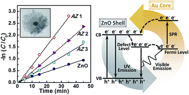
The associated underlying mechanism of electron transfer is proposed, as depicted in Scheme 1. Under UV excitation, the weak UV and strong visible emissions of pure ZnO indicate that only a small portion of the electrons in CB of ZnO can directly recombine with the holes in ZnO valence band (VB), whilst most excited electrons move to the defect level (centered at ∼550 nm). It is reported that the work function of ZnO is higher than that of Au in the ZnO–Au heterostructures, and the Fermi level (EF) of Au is located ∼1.55 eV below CB of ZnO.6,28 Given that the band gap of ZnO is 3.30 eV, and the green emission of ZnO (2.25 eV) is dominantly attributed to the electron transfer from the defect energy level of ZnO,28 it can be deduced that the defect level of ZnO lies slightly higher than EF of Au. This allows electrons flow from the former to the latter. Meanwhile, the strong visible emission of ZnO can excite the SPR of Au NPs, so that many excited Au electrons can be transferred back to CB of ZnO. In this way, an internal electron circulation is realized within this Au@ZnO system. As a result, the visible emission is largely quenched and the UV emission is significantly enhanced. It is worthy to mention that, the concave centered at ∼530 nm in the PL of AZ2 and AZ3 provides direct evidence on the SPR absorption of Au NPs from visible emission of ZnO.


image file: c5ra11653h-s1.tif
Scheme 1 Schematic diagram of the electron transfer of the Au@ZnO nanostructures.

To explore the photocatalytic performance of Au@ZnO, the degradation of RhB in aqueous solution under UV light irradiation was selected as a model reaction. Fig. 4a shows the curves of C/C0 versus time for RhB solution in present of Au NPs, ZnO NPs, AZ1, AZ2 and AZ3 respectively under otherwise identical conditions, together with the control group without addition of any agents. C0 is the initial concentration of RhB and C is the concentration of RhB at a particular time, t, measured from the relative intensities of the major absorbance of RhB (Fig. S4). Similar to the control group, Au NPs alone only produce weak degradation, with less than 20% of RhB is transformed. On the contrary, for the other four samples, evident visual discoloration accompanying with remarkable decrease of the absorption features of RhB is observed. For ZnO, 60% of RhB is decomposed within 45 min. The degradation of RhB is rather thorough for Au@ZnO, 80% for AZ3 and 90% for AZ2. Strikingly, it is noted that for AZ1, the reaction is much quicker, with more than 95% of RhB exhausted within 30 min. The reaction follows pseudo-first-order kinetics, ln(C0/C) = kt,25,29 as convinced by the linear fitting in Fig. 4b. The calculated k, i.e. the reaction rate constant of each sample is listed in Table 1. It is found that kAZ1 is as high as 4-fold of kZnO, indicating the significantly enhanced UV photocatalytic properties of Au@ZnO.


image file: c5ra11653h-f4.tif
Fig. 4 (a) Photocatalytic activity and (b) kinetics of pure ZnO, AZ1, AZ2, and AZ3 samples for degradation of RhB under the irradiation of UV light (λ = 365 nm).
Table 1 Reaction rate constant (k) of AZ1, AZ2, AZ3, and ZnO samples for photocatalytic degradation of RhB under UV irradiation
  AZ1 AZ2 AZ3 ZnO
k (min−1) 0.0815 0.0536 0.0369 0.0206
R2 0.9944 0.9958 0.9912 0.9941


In the literature, the enhanced UV photocatalytic performance of metal/ZnO hybrids was normally attributed to increased electron–hole separation in present of the metal NPs decorated on ZnO surfaces, where the injected electrons from metal nanoparticles and the holes in ZnO can both contribute to the catalytic reaction.6,14–16 As a result of such electron transfer process, enhanced UV photocatalytic properties is inevitably accompanying with quenched UV emission.14–18 However, for Au@ZnO in this work, the distinct bidirectional electron transfer shown in Scheme 1 delivers a totally different photocatalytic route. The Au cores here are not directly involved in the catalytic process. The electron transfer from the defect level of ZnO to EF of Au can enhance the separation of electrons and holes, and improve the catalytic efficiency of holes in ZnO. Meanwhile, the process of transferring excited electrons in Au to ZnO CB not only remarkably increases the ZnO UV emission but also supplies ZnO free electrons, which also contribute to the enhanced photocatalytic activity. Generally, both a large surface area and a high crystallinity are preferred for photocatalytic performance of ZnO.30 The massive surface defects and impurities of small ZnO NPs may disturb their crystallinity and raise concerns on their photocatalytic activity. However, in this work, exactly thanking the very small crystalline size of ZnO for its strong defects-related visible emission in green light region hence efficient contribution to the SPR absorption of the Au cores, the internal circular electron transfer between the Au cores and ZnO shells is enabled, and both the UV emission and the UV photocatalytic capability are enhanced eventually.

Conclusions

We have successfully fabricated a series of Au@ZnO with the Au core surrounded by small ZnO nanocrystallines owing strong visible emission in green light region. The special core–shell nanostructure enables the internal electron circulation between the Au core and the small ZnO NPs, resulting in increased UV and quenched visible emissions. It is demonstrated that such Au@ZnO possesses remarkably enhanced UV photocatalytic performance. This study may have provided a deeper understanding on the mechanisms and property optimization of metal–semiconductor nanostructures for photocatalytic applications.

Acknowledgements

This work is financially supported by the National Natural Science Foundation of China (Grant No. 21473045, No. 51401066, and No. 11104046), the Fundamental Research Funds from the Central University (Grant No. HIT.BRETIII.201216, HIT.BRETIII. 201225, HIT.BRETIV. 201313 and PIRS OF HIT A201503), and State Key Laboratory of Urban Water Resource and Environment, Harbin Institute of Technology (No. 2015TS06). M. Y. acknowledges financial support by the Recruitment Program of Global Experts, China.

Notes and references

  1. N. T. Nguyen, M. Altomare, J. Yoo and P. Schmuki, Adv. Mater., 2015, 27, 3208–3215 CrossRef CAS PubMed.
  2. L. Ma, S. Liang, X.-L. Liu, D.-J. Yang, L. Zhou and Q.-Q. Wang, Adv. Funct. Mater., 2015, 25, 898–904 CrossRef CAS PubMed.
  3. L. Xu, F. Zhang, X. Song, Z. Yin and Y. Bu, J. Mater. Chem. A, 2015, 3, 5923–5933 CAS.
  4. C. Yu, K. Yang, Y. Xie, Q. Fan, J. C. Yu, Q. Shu and C. Wang, Nanoscale, 2013, 5, 2142–2151 RSC.
  5. M. Ahmad, S. Yingying, A. Nisar, H. Sun, W. Shen, M. Wei and J. Zhu, J. Mater. Chem., 2011, 21, 7723–7729 RSC.
  6. S. T. Kochuveedu, Y. H. Jang and D. H. Kim, Chem. Soc. Rev., 2013, 42, 8467–8493 RSC.
  7. W. He, H.-K. Kim, W. G. Wamer, D. Melka, J. H. Callahan and J.-J. Yin, J. Am. Chem. Soc., 2014, 136, 750–757 CrossRef CAS PubMed.
  8. L. Zhang, L. Du, X. Yu, S. Tan, X. Cai, P. Yang, Y. Gu and W. Mai, ACS Appl. Mater. Interfaces, 2014, 6, 3623–3629 CAS.
  9. M. N. Tahir, F. Natalio, M. A. Cambaz, M. Panthöfer, R. Branscheid, U. Kolb and W. Tremel, Nanoscale, 2013, 5, 9944–9949 RSC.
  10. P. Li, Z. Wei, T. Wu, Q. Peng and Y. Li, J. Am. Chem. Soc., 2011, 133, 5660–5663 CrossRef CAS PubMed.
  11. K. X. Yao, X. Liu, L. Zhao, H. C. Zeng and Y. Han, Nanoscale, 2011, 3, 4195–4200 RSC.
  12. A. Senthilraja, B. Subash, B. Krishnakumar, D. Rajamanickam, M. Swaminathan and M. Shanthi, Mater. Sci. Semicond. Process., 2014, 22, 83–91 CrossRef CAS PubMed.
  13. A. Ghosh, P. Guha, A. K. Samantara, B. K. Jena, R. Bar, S. Ray and P. V. Satyam, ACS Appl. Mater. Interfaces, 2015, 7, 9486–9496 CAS.
  14. Y. Sun, L. Jiang, T. Zeng, J. Wei, L. Liu, Y. Jin, Z. Jiao and X. Sun, New J. Chem., 2015, 39, 2943–2948 RSC.
  15. J. Lee, H. S. Shim, M. Lee, J. K. Song and D. Lee, J. Phys. Chem. Lett., 2011, 2, 2840–2845 CrossRef CAS.
  16. N. Udawatte, M. Lee, J. Kim and D. Lee, ACS Appl. Mater. Interfaces, 2011, 3, 4531–4538 CAS.
  17. M. D. R. Peralta, U. Pal and R. S. Zeferino, ACS Appl. Mater. Interfaces, 2012, 4, 4807–4816 Search PubMed.
  18. Y. Chen, D. Zeng, K. Zhang, A. Lu, L. Wang and D.-L. Peng, Nanoscale, 2014, 6, 874–881 RSC.
  19. X. Hou, L. Wang, G. He and J. Hao, CrystEngComm, 2012, 14, 5158–5162 RSC.
  20. A. Ghosh, R. R. Juluri, P. Guha, R. Sathyavathi, A. Dash, B. K. Jena and P. V. Satyam, J. Phys. D: Appl. Phys., 2015, 48, 055303 CrossRef.
  21. W.-Q. Zhang, Y. Lu, T.-K. Zhang, W. Xu, M. Zhang and S.-H. Yu, J. Phys. Chem. C, 2008, 112, 19872–19877 CAS.
  22. C. W. Cheng, E. J. Sie, B. Liu, C. H. A. Huan, T. C. Sum, H. D. Sun and H. J. Fan, Appl. Phys. Lett., 2010, 96, 071107 CrossRef PubMed.
  23. J. Geng, G.-H. Song, X.-D. Jia, F.-F. Cheng and J.-J. Zhu, J. Phys. Chem. C, 2012, 116, 4517–4525 CAS.
  24. T. Wang, B. Jin, Z. Jiao, G. Lu, J. Ye and Y. Bi, J. Mater. Chem. A, 2014, 2, 15553–15559 CAS.
  25. M. Misra, P. Kapur and M. L. Singla, Appl. Catal., B, 2014, 150–151, 605–611 CrossRef CAS PubMed.
  26. N. Zhang, S. Liu, X. Fu and Y.-J. Xu, J. Phys. Chem. C, 2011, 115, 9136–9145 CAS.
  27. G. Frens, Nature, Phys. Sci., 1973, 241, 20–22 CrossRef CAS PubMed.
  28. H. Lin, C. Cheng, Y. Chou, L. Huang, Y. Chen and K. Tsen, Opt. Express, 2006, 14, 2372–2379 CrossRef CAS.
  29. Q. Deng, X. Duan, D. H. L. Ng, H. Tang, Y. Yang, M. Kong, Z. Wu, W. Cai and G. Wang, ACS Appl. Mater. Interfaces, 2012, 4, 6030–6037 CAS.
  30. J. Becker, K. R. Raghupathi, J. S. Pierre, D. Zhao and R. T. Koodali, J. Phys. Chem. C, 2011, 115, 13844–13850 CAS.

Footnote

Electronic supplementary information (ESI) available. See DOI: 10.1039/c5ra11653h

This journal is © The Royal Society of Chemistry 2015
Click here to see how this site uses Cookies. View our privacy policy here.