
Carbon nanotubes@metal–organic frameworks as Mn-based symmetrical supercapacitor electrodes for enhanced charge storage†
Yidong Zhang,
Baoping Lin*,
Ying Sun,
Xueqin Zhang,
Hong Yang and
Junchuan Wang
School of Chemistry and Chemical Engineering, Southeast University, Nanjing 211189, China. E-mail: lbp@seu.edu.cn; Fax: +86-25-52090616; Tel: +86-25-52090616
First published on 29th June 2015
Abstract
A hybrid material of carbon nanotubes (CNTs) and Mn-based metal organic frameworks (Mn-MOF) was synthesized and used as a Mn-based supercapacitor electrode material. The incorporation of CNTs into Mn-MOF led to an inherent improvement in conductivity and an intrinsic increase in specific capacitance (from 43.2 F g−1 for pure Mn-MOF to 203.1 F g−1 for CNTs@Mn-MOF). Furthermore, the symmetrical supercapacitor based on the CNTs@Mn-MOF exhibited excellent power density and outstanding stability even after 3000 cycles with 88% retention of the initial capacitance. This research exploited a new direction for developing Mn-based supercapacitor materials and provided an effective method to improve capacitive performance of MOFs materials.
Introduction
Recently, supercapacitor electrode materials, such as the oxides of Ru, Ni, Co, Cu, Fe, V and Mn, have attracted great research interest because of their excellent pseudocapacitance.1 Among them, manganese oxides (MnOx) are considered to be the most promising electrode materials due to their wide potential ranges, low-cost and environmentally friendly nature.2,3 To date, Mn-based supercapacitor materials can be classified into two broad categories: pure MnOx with various crystal structures and hybrid composites of MnOx.4 In the former category, MnOx without any doping have been directly used as electrode materials, including MnO, MnO2, Mn2O3, Mn3O4.5–11 However, these single materials often produce low capacitances and weak cycle stabilities due to their poor electrical conductivities. Therefore, various hybrid composites of MnOx have been synthesized to overcome this shortage. The materials used to dope MnOx are mainly in three cases: carbon materials such as carbon black, acetylene black, CNTs and exfoliated graphite;12–14 metal oxides including oxides of Ni, Ru, Cu, Fe, Co, Mo and Ag;15,16 and conducting polymers e.g. polyaniline, poly(3-methylthiophene), poly(3,4-ethylenedioxythiophene) and polypyrrole.17,18 Though such hybrid composites of MnOx, to some extent, have showed better electrical conductivities than pure MnOx materials, they produced a number of new disadvantages at the same time, such as reduction of capacitance, increase of inherent contact resistances and structural instability. Therefore, it is essential to develop new Mn-based electrode materials to ameliorate these problems.Metal–organic frameworks (MOFs) have received huge attention as attractive materials with chemical and structural diversity in recent years. Compared with traditional materials, MOFs show significant advantages due to their high accessible surface areas, tuneable pore sizes, open metal sites and ordered crystalline structures.19 They have been widely applied in many area such as catalysis,20 gas separation,21 drug storage and delivery,22 imaging and sensing,23 optoelectronics24 or energy storage.25,26 However, the investigation of MOFs used as electrode materials for supercapacitors is quite lacking. In the original studies, MOFs were only employed as templates for the preparation of either nano–micro scale metal-oxide materials or microporous carbon materials.27–30 Until recently, more and more MOFs based on various metals were directly used as electrode materials for supercapacitors. Thus, in the following paragraph we will make a short overview of the most relevant reports.
To the best of our knowledge, the first report demonstrating MOFs as supercapacitor materials has been made by D. Y. Lee et al.,31 in which the Co-MOF material was deposited on an Indium doped Tin Oxide (ITO) substrate as a film to form the working electrode. This material showed a specific capacitance of 206.76 F g−1 and a loss of only 1.5% in capacitance for 1000 electrochemical life cycle stability test. Another three Co-based MOFs were synthesized by the same authors to study the influence of MOFs microstructure on the electrochemical properties by controlling the length of organic linkers.32 The best of them exhibited supercapacitive properties with 179.2 F g−1, 31.4 W h kg−1 and 5.64 kW kg−1 of specific capacitance, energy density and power density, respectively. Afterwards, two porous MOFs based on Zn and Cd which were deposited on glassy carbon electrodes were reported by J. Lin provided capacitance values of 23 and 22 F g−1, respectively.33 Further, M. Du reported a mesoporous In-based MOF material with 1-D hexagonal channels, which provided a capacitance of 81 F g−1 (1 A g−1) and maintain about 100% of its maximum value after cycling 6000 times.34 Almost immediately, a series of Fe-based MOFs were synthesized with a best capacitance of 57.5 F g−1 in 0.1 M K2SO4 solution.35 Obviously, the above MOFs materials have had limited success in supercapacitor. Nevertheless, the Ni-based MOF36 with layered structure and Zn-doped Ni-MOF37 with a flower-like microsphere were successfully synthesized by M. Wei and co-workers, both of which displayed high specific capacitance, good rate capability and good cycling stability. They found that the outstanding electrochemical properties were attributed to the intrinsic characteristics of the MOFs including layered structure, enlarged interlayer distance and porous feature. Between the two reports, Kang et al. carried out a study of 23 different graphene-doped nMOFs,38 in which a series of Zr-, Co-, Ni-, Zn- and Cu-based MOFs have been researched in detail. Particularly, graphene was doped into nMOFs as a physical mixture to increase the conductivity of the materials. And the electrochemical tests demonstrated that several of the graphene-doped nMOFs showed good performance, the Zr-MOF material could even reach a high specific capacitance of 726 F g−1 at a current density of 0.88 mA cm−3. However, the graphene was dispread in organic solvent for several times before it was coated on electrode. In the latest report, a composite material of Cu-based MOF and reduced graphene oxide (rGO) exhibited a specific capacitance of 385 F g−1 at 1 A g−1, which was spray-coated on carbon fiber paper to fabricate a supercapacitor.39 Though the method was relatively effective to improve the electrical properties of MOFs, it was cumbersome and complicated. Thus, it is quite necessary to find a new method to modify MOFs, which is not only effective but also simple. In addition, another important phenomenon has caught our attention. Basically, all commonly used metals have been studied as MOFs materials for supercapacitors except for manganese. Meanwhile, the Mn-based materials, typically possessing wider potential ranges in comparison with other metal based materials, have played an important role in supercapacitor materials for a long time. Therefore, it is necessary to introduce Mn-based MOFs as supercapacitor electrode materials and further, find a simple and effective method to modify them for excellent capacitance, great structural flexibility and good cycle stability. One effective modification approach is to incorporate carbon nanotubes (CNTs) into MOFs, which can obviously improve the properties of MOF materials.40,41 The use of CNTs as composite fillers has been investigated in various MOFs, such as MOF-5![[thin space (1/6-em)]](https://www.rsc.org/images/entities/char_2009.gif) 42 and HKUST-1,43,44 in which the CNTs with carboxylic groups provide homogeneous nucleation sites to support a continuous metal framework growth. Herein, modifying MOFs with CNTs can eliminate most of the limitations of traditional Mn-based electrode materials. Motivated by these results, we fabricated a hybrid MOF material by incorporating CNTs into a facile Mn-MOF with a simple hydrothermal method for high-performance supercapacitive energy storage.
42 and HKUST-1,43,44 in which the CNTs with carboxylic groups provide homogeneous nucleation sites to support a continuous metal framework growth. Herein, modifying MOFs with CNTs can eliminate most of the limitations of traditional Mn-based electrode materials. Motivated by these results, we fabricated a hybrid MOF material by incorporating CNTs into a facile Mn-MOF with a simple hydrothermal method for high-performance supercapacitive energy storage.
In the present work, a composite of Mn(C8H4O4)(H2O)2 (where H2C8H4O4 = p-benzenedicarboxylic acid)45 incorporated with CNTs was successfully synthesized and used as a new type of Mn-based supercapacitor electrode material. The specific capacitance values of this material was 7.1- and 15-fold higher than those of the pure Mn-MOF at 1 and 20 A g−1, respectively. A symmetric supercapacitor of the CNTs@Mn-MOF was fabricated, and it displayed an maximum energy density of 6.9 W h kg−1 and a maximum power density of 2240 W kg−1. All the materials and their electrochemical properties were investigated in detail.
Experimental details
Materials preparation
Electrochemical measurements
| Cg = I × Δt/(m × ΔV) |
| 1/Ccell = (1/C+ + 1/C−) = I × (Δt/ΔV) × (1/m+ + 1/m−) |
Results and discussion
The CNTs@Mn-MOF composites and Mn-MOF were synthesized by a facile hydrothermal method. The Mn-MOF structure (Fig. S1†) consists of alternating layers which were perpendicular to direction a. And these layers were connected by hydrogen bonds between Mn-coordinated water molecules. Each layer was built up from one-dimensional (1D) chains of terephthalate anions and octahedrally coordinated metal cations extended parallel to the a-axis. Fig. 1 shows the detail hydrogen-bonding network in Mn-MOF. The delineating of the structure suggests two potential hydrogen bonds between each water-molecule H atom and a carboxylate O atom. These abounding hydrogen-bonds, which ensure cohesion of the structure, connected the 1-D layers into 3-D networks. And notably, two reported Ni-MOF had been confirmed to achieve excellent electrochemical performance due to the same layers-hydrogen bonds structure.36,37 The morphologies and structures of the CNTs@Mn-MOF composites were examined by SEM and TEM (Fig. 2). The CNTs@Mn-MOF morphology was characterized by well-defined hexagonal blocks 3–8 μm in each edge length (Fig. 2a). The regularly stick-like dents on the smooth crystal surface (Fig. 2b) indicated that CNTs were incorporated inside Mn-MOF, which was clearly displayed in TEM (Fig. 2c and d). The micron-scale blocks were grinded to fragments to obtain an observable sample before test. The CNTs embedded in the sheets, which act as composite fillers in the MOF crystal, can be seen clearly from the TEM image. As presumed in the previous report, the CNTs@Mn-MOF crystals were formed by heteronucleation and crystal growth on the carboxylic groups of the CNTs.42 | ||
| Fig. 1 The hydrogen-bonding network in Mn-MOF. | ||
 | ||
| Fig. 2 (a and b) SEM (the insets show enlarged views of the crystal surface), (c and d) TEM of CNTs@Mn-MOF in different views (white arrows indicate CNTs). | ||
To investigate the filling of CNTs in more details, the composites were examined by various methods. Fig. 3a exhibits the powder XRD patterns of Mn-MOF and CNTs@Mn-MOF. The diffraction pattern of the Mn-MOF was in good consistent with that simulated from the single-crystal data of Mn(C8H4O4)(H2O)2 (CCDC 195798).45 In contrast, the powder XRD pattern of CNTs@Mn-MOF presented a new peak at 2θ = 26–27°, which normally corresponded to the (0 0 2) plane of the CNTs component. All of the other diffraction peaks for CNTs@Mn-MOF showed that the sketch of the Mn-MOF crystal was well retained even after modification with the CNTs. TG curves, shown in Fig. 3b, indicated that incorporating CNTs enhanced thermal stability of Mn-MOF. An initial weight loss of 14.1% up to 190 °C was due to the loss of solvated water molecules in Mn-MOF, and it was less than that in CNTs@Mn-MOF because of the pore activation by CNTs. Furthermore, CNTs in Mn-MOF enhanced thermal stability, as demonstrated by a rise in decomposition temperature from 364 to 410 °C, which corresponded to the initial decomposition of Mn-MOF to yield manganese oxides. The behavior of TGA was consistent with the previous reports.42,43 Fig. 3c shows the XPS analysis. The major peaks centred at around 641.8, 646.5, 653.7 and 658.0 eV, corresponding to Mn 2p3/2, Mn 2p3/2 satellites, Mn 2p1/2 and Mn 2p1/2 satellites, respectively, which were characteristic of Mn2+ and in good agreement with previous literature reports.46 The FTIR spectra of CNTs, Mn-MOF and CNTs@Mn-MOF were shown in Fig. 3d. As for Mn-MOF, the asymmetric stretching of the carboxylate group in the terephthalic acid linker appeared at around 1629 and 1558 cm−1 and its symmetric stretching appeared around 1386 cm−1. The stretching vibrations of water molecules at around 3450, 3360 and 3259 cm−1 indicated that coordinated H2O molecules were present within the Mn-MOF material.45,47 FTIR spectrum of Mn-MOF was found to be in agreement with the previous literature report.36 Compared with the spectra of Mn-MOF and CNTs, the relevant CNTs peaks in CNTs@Mn-MOF, which normally around 1629 and 1386 cm−1, were swamped by the high intensity Mn-MOF peaks. Therefore, the FTIR spectrum of CNTs@Mn-MOF was similar to that of Mn-MOF. The various characterization suggests that we successfully incorporated CNTs into Mn-MOF, and a novel CNTs@Mn-MOF composite material was obtained.
 | ||
| Fig. 3 Characterization results of CNTs@Mn-MOF and Mn-MOF: (a) XRD patterns, (b) TG curves, (c) XPS, and (d) FTIR spectra. | ||
To investigate the supercapacitive performance of CNTs@Mn-MOF as electrode material, we carried out electrochemical measurements by using an electrochemical workstation. Its capacitive behavior was first investigated by CV in Fig. 4. As well as the reported CV curves for MnO@C materials, the slight kink in the redox peak was also observed for the CNTs@Mn-MOF, which were thought to be caused by faradaic reactions of the electrode materials and carbon.48,49 The proposed reaction that may account for this can be expressed as follows:50
| Mn(C8H4O4)(H2O)2 + C+ + e− ↔ MnC(C8H4O4)(H2O)2 |
 | ||
| Fig. 4 CV curves of CNTs@Mn-MOF tested by a three-electrode system at different scan rates in 1 M Na2SO4. | ||
The CV curves under different scanning rates, from 5 to 100 mV s−1, presented nearly rectangular feature, indicating a close-to-ideal pseudo-capacitive nature of the electrode. The CNTs@Mn-MOF composite exhibited a high specific capacitance of 206 F g−1 at a scan rate of 5 mV s−1, which decreased to 112.5 F g−1 at a high scan rate of 100 mV s−1. Note that, the capacitive contributions from blank carbon fiber paper are negligible (Fig. S2†). The exact rate performances were further evaluated by galvanostatic charge–discharge (GCD) measurements, the charging and discharging curves of different current rates, including 1, 2, 3, 4, 10 and 20 A g−1 (Fig. S3†). All these curves present a symmetric feature, suggesting ideal pseudo-capacitive nature of fast charge–discharge processes. Accordingly, in a wide potential window of 1.0 V, the specific capacitance can reach 203.1 F g−1 at a current density of 1 A g−1. For MnII-based materials, there are only a few reports on the application of supercapacitors. It is worth noting that the specific capacitance of 203.1 F g−1 reported here is much higher than that of some previous reported composites of mesoporous carbon@MnO49 (160 F g−1 at 1 A g−1) and graphene oxide@MnO50 (51.5 F g−1 at 0.5 A g−1). To the best of our knowledge, the obtained single-electrode capacitances of CNTs@Mn-MOF are superior to the available reports on MnII-based supercapacitor electrodes and spur the low capacitance of MnO materials to a higher level.
To confirm the influence of modification by CNTs on the supercapacitive properties of Mn-MOF material, we carried out electrochemical measurements in a three-electrode system with the three materials (Fig. 5). Both CV (all at 100 mV s−1, Fig. 5a) and GCD (all at 1 A g−1, Fig. 5c) tests of Mn-MOF and CNTs showed much lower capacitances when compared with that of CNTs@Mn-MOF. The maximum specific capacitances of CNTs@Mn-MOF, Mn-MOF and CNTs were 203.1, 43.2, 72.9 F g−1 at a scan rate of 5 mV s−1 and 202.8, 28.4, 60 F g−1 at a current density of 1 A g−1, respectively. A standard rectangular CV curve for CNTs with a potential window of 0.5 V (vs. SCE) indicated a feature of electrical double layer capacitors. The low capacitance of 72.9 F g−1 (at 5 mV s−1) was in the reported rang of 50–100 F g−1 for CNTs, which was restricted by the single property of double layer capacity without faradic reactions.52 CV curve of Mn-MOF was similar to that of CNTs@Mn-MOF, but with a relatively small area corresponded to a low capacitance, which was attributed to the poor conductivity of MOFs material. As clearly seen in Fig. 5b and d, the capacitance values of CNTs@Mn-MOF were 4.7-, 4.6-, 4.3-, 4.5-, 4.6-fold and 7.1-, 6.8-, 6.7, 11-, 15-fold higher than those of the composites at 5, 10, 20, 50, 100 mV s−1 and 1, 2, 3, 10, 20 A g−1 as well as pure Mn-MOF, respectively. As the results, it can be concluded here that adding CNTs to the Mn-MOF can overcome the poor electron conductive property of the MOFs material, which can lead to a much higher capacitance. This was also confirmed by Nyquist plots (Fig. S4†). The curves in low frequency were similar to each other while the slopes were steeper than 45° which associated with Warburg diffusion. The CNTs@Mn-MOF displayed a smaller semicircle at high frequencies than pure Mn-MOF, which illustrated that the kinetics performance of the material was improved by incorporation of CNTs. The Rs of CNTs@Mn-MOF, which was valued by the intercept of the real part of impedance with the x-axis, exhibited a significant decrease in comparison with pure Mn-MOF. Unsurprisingly, a slight increase of Rs was observed after long-term cycling, which was a normal behavior due to changes of material structure. This results indicated that the resistance of the electrolyte, intrinsic resistance of the substrate and contact resistance of MOF material were effectively improved by the incorporation of CNTs. As inside of the hybrid material, the CNTs were tightly attached to the MOF inwall, which was beneficial for mechanical reinforcement and enhancing electronic conduction. The important role of the CNTs in the structure on charge storage was due to their effects on regulating the electrical contact pathways between adjacent particles and providing an electron transport network. Therefore, the characteristics combination of Mn-MOF and CNTs leads to not only a dramatic improvement in electrical conductivity but also in specific capacitance.
 | ||
| Fig. 5 (a) CV curves in 1 M Na2SO4 at 100 mV s−1, (b) the specific capacitances vs. scan rates, (c) GCD curves at 1 A g−1, and (d) the specific capacitances vs. applied current densities. | ||
In order to demonstrate the practical performance of CNTs@Mn-MOF, a symmetrical supercapacitor device was fabricated using the hybrid material as electrodes and one piece of polypropylene membrane as a separator. As presented by typical GCD curves under various current densities in Fig. 6a, the optimized symmetrical cell can provide a maximum specific capacitance of 50.3 F g−1 at 0.25 A g−1. When the current densities increases to 0.5, 1, 2, 3, 5 and 10 A g−1, the specific capacitance of the symmetrical cell decreases to 48.9, 47.7, 40.8, 36.9, 31.2 and 23.4 F g−1, retaining 97.4%, 95%, 81.6%, 73.8%, 62% and 59.6% of its value at 0.25 A g−1, respectively. The excellent rate performances were due to the Mn-MOF incorporated with functionally CNTs. It is accepted that the capacitance gradually decreases with the increase of current density, which is attributed to the low utilization of active materials under high charge–discharge current densities. Fig. 6b shows the dependence of IR drop on applied current density, and it was fitted to a linear plot. The slop demonstrates corresponding internal resistance. As for the well-fitted line (IR = 0.0041 + 0.036I), the initial voltage loss was small even at high current densities, indicating a low internal resistance and fast I–V response in the symmetrical supercapacitor.
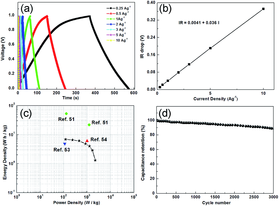 | ||
| Fig. 6 (a) GCD curves of symmetrical cells relative to current densities, (b) dependence of IR drop on current densities, (c) Ragone plot of the symmetrical cells, (d) cycle performance of symmetrical supercapacitor at 5 A g−1. | ||
Fig. 6c displays typical Ragone plots (power density vs. energy density), with an operation voltage of 1 V. This symmetrical device exhibited an energy density of 6.9 W h kg−1 at a power density of 122.6 W kg−1. In addition, the power density can reach 2240 W kg−1 when maintaining the energy density of 1.3 W h kg−1. Up to now, Mn-MOF supercapacitor has not been reported. Therefore, we selected a composite of MnO@NCS,51 a symmetrical supercapacitor of MnO253 and a nanocomposite of CNT/MnO254 to make a comparison with our work. Obviously, the symmetrical supercapacitor in our work displays much better performance. Fig. 6d shows the long-term cycling stability of the symmetrical supercapacitor, measured by the GCD technique at 5 A g−1. The capacitance retentions for the symmetrical supercapacitor was still maintained at 88% of its highest value after 3000 cycles (SEM image in Fig. S5†), indicating that the CNTs@Mn-MOF material not only had an excellent specific capacitance but also had an outstanding cycling stability. This cycling stability is superior to the typical MnOx-based supercapacitor.55,56
Conclusions
In summary, a composite of CNTs@Mn-MOF was synthesized via a facile hydrothermal process. In the constructive structure, the CNTs act as strongly mechanical supports and conductive networks for the hybrid MOF material. An excellent capacitance of 203.1 F g−1 was achieved in a three electrode system. In addition, the symmetrical supercapacitor showed good performance within the maximum energy density of 6.9 W h kg−1 and maximum power density of 2240 W kg−1. Moreover, 88% of its highest specific capacitance was maintained after 3000 cycles at 5 A g−1. The present study indicates the CNTs@Mn-MOF as a potential candidate for Mn-based supercapacitors and brings new method to improve supercapacitive performance of various MOFs material. We believe that this hybrid MOFs composite can open the door to develop new materials in electrical energy storage.Acknowledgements
This work was financially supported by the National Natural Science Foundation of China (Grant No. 21374016) and the Production and Research Prospective Joint Research Project of Jiangsu Province of China (BY2011153).Notes and references
- J. Wang, H. Tang, H. Ren, R. Yu, J. Qi, D. Mao, H. Zhao and D. Wang, J. Adv. Sci., 2014, 1, 1400011 Search PubMed.
- W. F. Wei, X. W. Cui, W. X. Chen and D. G. Ivey, Chem. Soc. Rev., 2011, 40, 1697 RSC.
- R. Liu and S. B. Lee, J. Am. Chem. Soc., 2008, 130, 2942 CrossRef CAS PubMed.
- S. W. Zhang and G. Z. Chen, Energy Mater., 2008, 3, 186 CrossRef CAS PubMed.
- F. Y. Yang, M. S. Zhao and Q. J. Sun, RSC Adv., 2015, 5, 9843 RSC.
- S. L. Chen, F. Liu and Q. J. Xiang, Electrochim. Acta, 2013, 106, 360 CrossRef CAS PubMed.
- G. Yu, L. Hu, M. Vosgueritchian, H. Wang, X. Xie, J. R. McDonough, X. Cui, Y. Cui and Z. Bao, Nano Lett., 2011, 11, 2905 CrossRef CAS PubMed.
- C. Liu, F. Li, L. P. Ma and H. M. Cheng, Adv. Mater., 2010, 22, E28 CrossRef CAS PubMed.
- T. Brousse, M. Toupin, R. Dugas, L. Athouel, O. Crosnier and D. Belanger, J. Electrochem. Soc., 2006, 153, A2171 CrossRef CAS PubMed.
- O. Ghodbane, J. L. Pascal and F. Favier, ACS Appl. Mater. Interfaces, 2009, 1, 1130 CAS.
- R. N. Reddy and R. G. Reddy, J. Power Sources, 2003, 124, 330 CrossRef CAS.
- X. Jin, W. Zhou, S. Zhang and G. Z. Chen, Small, 2007, 3, 1513 CrossRef CAS PubMed.
- S. B. Ma, K. Y. Ahn, E. S. Lee, K. H. Oh and K. B. Kim, Carbon, 2007, 45, 375 CrossRef CAS PubMed.
- Z. Yu, B. Duong, D. Abbitt and J. Thomas, Adv. Mater., 2013, 25, 3302 CrossRef CAS PubMed.
- M. Nakayama, A. Tanaka, S. Konishi and K. Ogura, J. Mater. Res., 2004, 19, 1509 CrossRef CAS.
- H. Xia, C. Hong, X. Shi, B. Li, G. Yuan, Q. Yao and J. Xie, J. Mater. Chem. A, 2015, 3, 1216 CAS.
- E. C. Rios, A. V. Rosario, R. M. Q. Mello and L. Micaroni, J. Power Sources, 2007, 163, 1137 CrossRef CAS PubMed.
- S. R. Sivakkumar, J. M. Ko, D. Y. Kim, B. C. Kim and G. G. Wallace, Electrochim. Acta, 2007, 52, 7377 CrossRef CAS PubMed.
- S. L. James, Chem. Soc. Rev., 2003, 32, 276 RSC.
- A. Corma, H. Garcia and F. X. Llabresi Xamena, Chem. Rev., 2010, 110, 4606 CrossRef CAS PubMed.
- A. U. Czaja, N. Trukhan and U. Mueller, Chem. Soc. Rev., 2009, 38, 284 RSC.
- P. Horcajada, T. Chalati, C. Serre, B. Gillet, C. Sebrie, T. Baati, J. F. Eubank, D. Heurtaux, P. Clayette, C. Kreuz, J. S. Chang, Y. K. Hwang, V. Marsaud, P. N. Bories, L. Cynober, S. Gil, G. Ferey, P. Couvreur and R. Gref, Nat. Mater., 2010, 9, 172 CrossRef CAS PubMed.
- L. E. Kreno, K. Leong, O. K. Farha, M. Allendorf, R. P. Van Duyne and J. T. Hupp, Chem. Rev., 2012, 112, 1105 CrossRef CAS PubMed.
- H. Wu, W. Zhou and T. Yildirim, J. Am. Chem. Soc., 2007, 129, 5314 CrossRef CAS PubMed.
- N. L. Rosi, J. Eckert, M. Eddaoudi, D. T. Vodak, J. Kim, M. O. Keeffe and O. M. Yaghi, Science, 2003, 300, 1127 CrossRef CAS PubMed.
- F. Vilela, K. Zhang and M. Antonietti, Energy Environ. Sci., 2012, 5, 7819 CAS.
- C. Y. Su, A. M. Goforth, M. D. Smith, P. J. Pellechia and H. C. zurLoye, J. Am. Chem. Soc., 2004, 126, 3576 CrossRef CAS PubMed.
- F. Meng, Z. G. Fang, Z. X. Li, W. W. Xu, M. J. Wang, Y. P. Liu, J. Zhang, W. R. Wang, D. Y. Zhao and X. H. Guo, J. Mater. Chem. A, 2013, 1, 7235 CAS.
- H. L. Jiang, B. Liu, Y. Q. Lan, K. Kuratani, T. Akita, H. Shioyama, F. Zong and Q. Xu, J. Am. Chem. Soc., 2011, 133, 11854 CrossRef CAS PubMed.
- A. J. Amali, J. K. Sun and Q. Xu, Chem. Commun., 2014, 50, 1519 RSC.
- D. Y. Lee, S. J. Yoon, N. K. Shrestha, S.-H. Lee, H. Ahn and S.-H. Han, Microporous Mesoporous Mater., 2012, 153, 163 CrossRef CAS PubMed.
- D. Y. Lee, D. V. Shinde, E. K. Kim, W. Lee, I. W. Oh, N. K. Shrestha, J. K. Lee and S. H. Han, Microporous Mesoporous Mater., 2013, 171, 53 CrossRef CAS PubMed.
- Y. Gong, J. Li, P. G. Jiang, Q. F. Li and J. H. Lin, Dalton Trans., 2013, 42, 1603 RSC.
- M. Du, M. Chen, X. G. Yang, J. Wen, X. Wang, S. M. Fang and C. S. Liu, J. Mater. Chem. A, 2014, 2, 9828 CAS.
- N. Campagnol, R. Romero-Vara, W. Deleu, L. Stappers, K. Binnemans, D. E. de Vos and J. Fransaer, ChemElectroChem, 2014, 1, 1182 CrossRef CAS PubMed.
- J. Yang, P. Xiong, C. Zheng, H. Qiu and M. Wei, J. Mater. Chem. A, 2014, 2, 16640 CAS.
- J. Yang, C. Zheng, P. Xiong, Y. Li and M. Wei, J. Mater. Chem. A, 2014, 2, 19005 CAS.
- K. M. Choi, H. M. Jeong, J. H. Park, Y. B. Zhang, J. K. Kang and O. M. Yaghi, ACS Nano, 2014, 8, 7451 CrossRef CAS PubMed.
- P. Srimuk, S. Luanwuthi, A. Krittayavathananon and M. Sawangphruk, Electrochim. Acta, 2015, 157, 69 CrossRef CAS PubMed.
- J. T. Han, S. Y. Kim, J. S. Woo and G.-W. Lee, Adv. Mater., 2008, 20, 3724 CrossRef CAS PubMed.
- S. Berson, R. De Bettignies, S. Bailly, S. Guillerez and B. Jousselme, Adv. Funct. Mater., 2007, 17, 3363 CrossRef CAS PubMed.
- S. J. Yang, J. Y. Choi, H. K. Chae, J. H. Cho, K. S. Nahm and C. R. Park, Chem. Mater., 2009, 21, 1893 CrossRef CAS.
- Z. H. Xiang, Z. Hu, D. P. Cao, W. T. Yang, J. M. Lu, B. Y. Han and W. C. Wang, Angew. Chem., Int. Ed., 2011, 50, 491 CrossRef CAS PubMed.
- M. Shoaee, M. W. Anderson and M. P. Attfield, Angew. Chem., Int. Ed., 2008, 47, 8525 CrossRef CAS PubMed.
- J. A. Kaduk, Acta Crystallogr., Sect. B: Struct. Sci., 2002, 58, 815 Search PubMed.
- M. A. Stranick, Surf. Sci. Spectra, 1999, 6, 47 CrossRef CAS.
- F. Zhang, L. Hao, L. J. Zhang and X. G. Zhang, Int. J. Electrochem. Sci., 2011, 6, 2943 CAS.
- Q. Y. Liao, N. Li, H. Cui and C. X. Wang, J. Mater. Chem. A, 2013, 1, 13715 CAS.
- T. Wang, Z. Peng, Y. Wang, J. Tang and G. Zheng, Sci. Rep., 2013, 3, 2693 Search PubMed.
- D. Antiohos, K. Pingmuang, M. S. Romano, S. Beirne, T. Romeo, P. Aitchison, A. Minett, G. Wallace, S. Phanichphant and J. Chen, Electrochim. Acta, 2013, 101, 99–108 CrossRef CAS PubMed.
- M. Yang, Y. Zhong, X. Zhou, J. Ren, L. Su, J. Wei and Z. Zhou, J. Mater. Chem. A, 2014, 2, 12519 CAS.
- L. L. Zhang, R. Zhou and X. S. Zhao, J. Mater. Chem., 2010, 20, 5983 RSC.
- S. Nagamuthu, S. Vijayakumar and G. Muralidharan, Ind. Eng. Chem. Res., 2013, 52, 18262 CrossRef CAS.
- Y. Jin, H. Chen, M. Chen, N. Liu and Q. Li, ACS Appl. Mater. Interfaces, 2013, 5, 3408 CAS.
- X. Zhao, L. Zhang, S. Murali, M. D. Stoller, Q. Zhang, Y. Zhu and R. S. Ruoff, ACS Nano, 2012, 6, 5404 CrossRef CAS PubMed.
- L. Mao, K. Zhang, H. S. O. Chan and J. S. Wu, J. Mater. Chem., 2012, 22, 1845 RSC.
Footnote |
| † Electronic supplementary information (ESI) available: Further details for structural figures, GCD, and EIS. See DOI: 10.1039/c5ra11597c |
| This journal is © The Royal Society of Chemistry 2015 |