
Fabrication of MIL-120 membranes supported by a-Al2O3 hollow ceramic fibers for H2 separation†
Songjie
Fan
*,
Shan
Wu
,
Jianhua
Liu
and
Dan
Liu
Research Institute of Medicine and Pharmacy, Qiqihar Medical University, China. E-mail: fansongjie@qmu.edu.cn
First published on 16th June 2015
Abstract
The synthesis conditions of MIL-120 membranes supported by a-Al2O3 hollow ceramic fibers (HCFs) were studied systemically. The continuous and compact MIL-120 membranes were successfully synthesised by secondary growth with in situ seeding step. The MIL-120 membrane shows the separation factors of H2–CO2, H2–CH4 and H2–N2 are 9.4, 7.9, and 7.3 respectively at 293 K and 1 bar with H2 permeance of 3.5 × 10⁻⁷ mol m−2 s−1 Pa−1 as well as high thermal stability.
Introduction
Metal–organic frameworks (MOFs), also known as porous coordination polymers (PCPs), are novel crystalline microporous materials involving metallic centers associated to organic ligands. For the past decades these materials have attracted much attention due to their potential application in gas adsorption and storage,1–3 selective molecular separation,4–7 and heterogeneous catalysis.8,9 Moreover, their highly adjustable structures and pore size as well as specific adsorption affinities make them candidates for fabrication of membranes for gas separation. However it remains a challenge to prepare a continuous MOF membrane for practical gas separation applications. There are two kinds of synthesis methods that are studied widely named direct growth10,11 and seed-assisted growth.12–14 Direct growth means the substrate which is immersed in the growth solution does not have any crystals previously attached to the surface. The nucleation, growth and intergrowth of crystals on the substrate all happen during the same fabrication step.15 It is a convenient method while many studies have demonstrated that the heterogeneous nucleation of MOF crystals on support surfaces is very poor,16,17 so it is rather difficult to prepare continuous MOF membranes by a direct solvothermal synthesis route. Many synthesis strategies were reported to solve this problem such as chemical modification of the substrate surface,4,18 and a ‘twin mental source’ technique.19 Consequently seed-assisted growth which is also called “secondary growth” is viewed as an effective method to synthesise MOF membrane.13,20 Seed-assisted growth could be described as firstly some small crystallites working as seeds should be synthesised and then through some seed-coating processes these seeds are attached with the surface of the substrate and finally the substrate coated with seeds is immersed in the secondary growth mother solution to grow. While to obtain small and homogeneous crystallites suitable as seeds is not an easy work usually. The seed-coating process is of great significance in this method and how to enhance the binding between the seeds and the substrates is always a challenge. Several seeding techniques are widely used these days including rubbing,21 dip coating,22,23 wiping, spin coating, heating and electrospinning.24 These methods are available for different MOF materials and substrates. It can be seen that though the seed-assisted growth could solve the problem of the poor heterogeneous nucleation of MOF crystals on the substrate surface, the operation is complex which is barely conducted in practical industrial application.Al4(OH)8[C10O8H2] (MIL-120) was first synthesised and reported by Thierry Loiseau et al.25 Its channels run along the c axis and the pore size is 5.4 × 4.7 Å which is appropriate to separate gases such as H2, CO2, N2 and CH4 whose molecular kinetic diameters are 2.9 Å, 3.3 Å, 3.6 Å and 3.8 Å respectively. Because the pore can not accommodate two different gas molecules at the same time and it exhibits quite high enthalpy of adsorption of methane (−27 kJ mol−1).25 Additionally, the low cost, facile synthesis and the remarkable stability of this material provide great potential in applications. Therefore, it can be viewed as a great candidate for the fabrication of membranes for gas separation. To the best of our knowledge so far no membrane of this MOF material is prepared. In this essay we systemically explored the synthesis conditions of the MIL-120 membrane on the surface of a-Al2O3 hollow ceramic fibers through a range of experiments and realised that the seeding step can be carried out with in situ growth as well which saves the troubles of the synthesis of seeds and the process of seed-coating. Finally, through secondary growth we successfully obtained continuous and compact MIL-120 membrane. The as-synthesised MIL-120 membrane exhibits moderate H2 separation performance among reported MOF membranes.15
Experimental
Materials
a-Al2O3 hollow ceramic fibers (HCFs,internal diameter is 2.5 mm, external diameter is 3.5 mm, the length is 30 mm, pore size of the inside layer: 200 nm, and pore size of outside layer: 1 μm, porosity: 30–40%, Hyflux membrane Co.) were used as substrate. Aluminum nitrate (Al(NO3)3·9H2O, 99+%) and pyromellitic acid (1,2,4,5-benzenetetracarboxylic acid, noted H4btec, C6H2(CO2H)4, 96%) was supplied by Aladdin Chemistry CO. Ltd. Sodium hydroxide and deionized water were used as received.Pre-treatment of HCFs
The a-Al2O3 hollow ceramic fibers (HCFs) as substrate were calcined under 773 K for 12 h to remove the organics from the pores and then cleaned thoroughly with deionized water under ultrasonication for three times. After that, they were sequentially treated with a solution of H2SO4 and H2O2 (H2SO4/H2O2 = 3/1, v/v, H2SO4 (18.4 mol L−1), H2O2 (30%W)) at 363 K for 8 h to introduce more hydroxyl groups to the substrate surface. Lastly, the substrates were washed with deionized water several times until the pH value of the water was about 7, and then dried at 353 K overnight.Synthesis
The synthesis mixture was made of aluminium nitrate, pyromellitic acid, aqueous sodium hydroxide solution (NaOH, 4 M) and deionized water. They were stirred under room temperature in a 15 ml teflon-lined stainless-steel autoclave. Then a substrate was placed horizontally at the bottom of the autoclave. The autoclave was sealed and heated in an oven (see detailed synthesis solution composition and synthesis conditions in Table 1). After cooling to room temperature, the substrate was taken out of the autoclave, thoroughly washed with deionized water under ultrasonication, and then dried at 353 K. The membrane was activated under vacuum for 7 h at 373 K to remove the solvent in the pores of the crystals before the gas separation measurement.| Sample no | Solution composition | Cryst | Substrate | ||||
|---|---|---|---|---|---|---|---|
| Al(NO3)3·9H2O (g) | H3btec (g) | NaOH (4 M, ml) | H2O (ml) | T (h) | T (K) | ||
| F-01 | 1.6 | 0.218 | 1.7 | 10 | 24 | 483 | HCF |
| F-02 | 1.2 | 0.218 | 1.7 | 10 | 24 | 483 | HCF |
| F-03 | 1.2 | 0.218 | 1.7 | 10 | 24 | 483 | F-01 |
| F-04 | 1.6 | 0.218 | 1.7 | 10 | 48 | 483 | HCF |
| F-05 | 0.8 | 0.218 | 1.7 | 10 | 24 | 483 | F-01 |
| F-06 | 0.8 | 0.218 | 1.7 | 10 | 48 | 483 | F-03 |
| F-07 | 1.2 | 0.218 | 1.7 | 10 | 48 | 483 | F-01 |
| F-08 | 1.2 | 0.218 | 1.7 | 10 | 72 | 483 | F-01 |
Characterization
X-ray diffraction (XRD) patterns were collected by a Siemens D5005 diffractometer using Cu kα radiation (λ = 1.5418 Å). Scanning electron microscopy (SEM, FE-SEM: JEOS JSM6700F) was applied to characterize the morphology of the membrane. The TGA was performed under air flow at a heating rate of 1 °C min−1 in the range of 22–800 °C with a Perkin-Elmer TGA thermogravimetric analyzer. To test the gas separation, the activated membrane was sealed in a membrane module which has been introduced in our earlier report.26,27 The volume ratio of gases were controlled by a soap film flow meter. The flow rate of the sweep gas Ar was controlled at 50 ml min−1. The feed flow rate was set to 100 ml min−1 for the single gas measurements. The total volumetric flow in the feed for binary gas measurements was 100 ml min−1 with each gas of 50 ml min−1. Then the mixture gases in the feed side were introduced into one side of the membrane from the inlet and the feed pressure is measured by a pressure gauge, while the outlet is connected with a vacuum valve. By controlling the vacuum valve we can regulate the permeation pressure. The permeate component through the membrane were taken by Ar into an on-line HP6890 gas chromatograph.Calculation of permeances and separation factor
The permeability is the ability to pass through a membrane and termed as the permeance (Pi (mol m−2 s−1 Pa−1)) for a single gas or a component in a mixture. It is calculated by eqn (1):where Ni (mol s−1) is the permeate flow rate of component i, Δpi (Pa) is the trans-membrane pressure drop of i, and A (m2) is the membrane area.

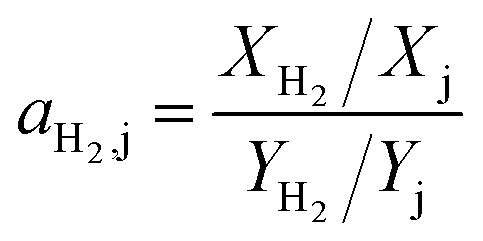
The selectivity of the membrane is defined as separation factor (ai,j): the ratio of the molar fractions X of the component i and j in the permeate divided by the ratio of the molar fractions Y of i and j in the feed. So the separation factor for hydrogen can be calculated according to eqn (2):
Results and discussion
Preparation and characterization of MIL-120 membrane
To fabricate the MOF membrane we designed many experiments and the details were listed in Table 1. The solution composition were prepared based on the earlier report.25 After 1 day's hydrothermal treatment we can see some tiny crystallites on the surface of the HCF. But the size and amount are far from forming a film as showed in Fig. 1b. Then we reduced the content of aluminum nitrate slightly expecting that aluminum in the substrate could participate in the crystallization (F-02). However, the result showed in Fig. 1c displays that no crystallite form on the surface of the substrate at all. Subsequently, we performed the third experiment (F-03) and it should be noticed that the substrate are from F-01. As seen in Fig. 1d, the substrate is covered by homogeneous plate like and spindly crystallites with the size of 1–2 μm thoroughly. But these crystallites are loose and not intergrown. Comparing F-01, F-02, and F-03, we may speculate that crystallization time is not enough for F-01 so we conducted F-04 but there are no obvious crystallites forming on the surface as shown in Fig. 1e. The reason may be that these tiny crystallites forming in the first step (F-01) work as seeds and facilitate the second step (F-03). We can view the F-01 step as the in situ seed formation procedure. Further reduction of aluminum nitrate content is not beneficial to the crystallites formation as well (F-05, Fig. 1f). The peak positions in the X-ray diffraction (XRD) pattern of the sample from F-03 match well with those of the simulated pattern, indicating the phase purity and homogeneity (Fig. S1†). The relative peak intensities of the membrane indicate the random orientation of MIL-120 crystals. As MIL-118 and MIL-121 are also synthesized by similar approach only depending on different pH range to control, we also exhibited their XRD patterns at the same time. | ||
| Fig. 1 SEM images of: the top-view of (a) the substrate (HCF); (b) F-01, (c) F-02, (d) F-03, (e) F-04 and (f) F-05. | ||
Even though the amount of these crystallites is enough to cover the substrate surface thoroughly, further growth is required for membrane formation. Based on the previous experience we conducted F-06 excepting that the third crystallization stage could promote these crystallites growth and form an intergrown membrane. However the SEM image (Fig. 2b) shows that through 2 days' hydrothermal treatment these original crystallites growed a little only with the size reaching to 3 μm. Comparing with F-03 whose size is about 2 μm, we could see that multi-step crystallization might be not an effective way to facilitate MIL-120 crystallites growth. By contrast crystallization time has become an essential factor now according to the results of F-07 and F-08. We can see that through 2 days' secondary growth prismatic MIL-120 crystals were well intergrown on the surface of the HCF support (Fig. 2c). With an enlarged view (Fig. 2d), no visible cracks and pinholes are found. Further lengthening the crystallization time would not promote the membrane quality obviously (F-08, Fig. 2e and f). So we identify the reaction condition of F-07 as optimal. The XRD patterns collected on the MIL-120 membrane of F-07, and F-08 are similar to the simulated MIL-120 pattern (Fig. S2†), which indicates that highly crystalline randomly oriented MOF crystals were grown on the substrate.
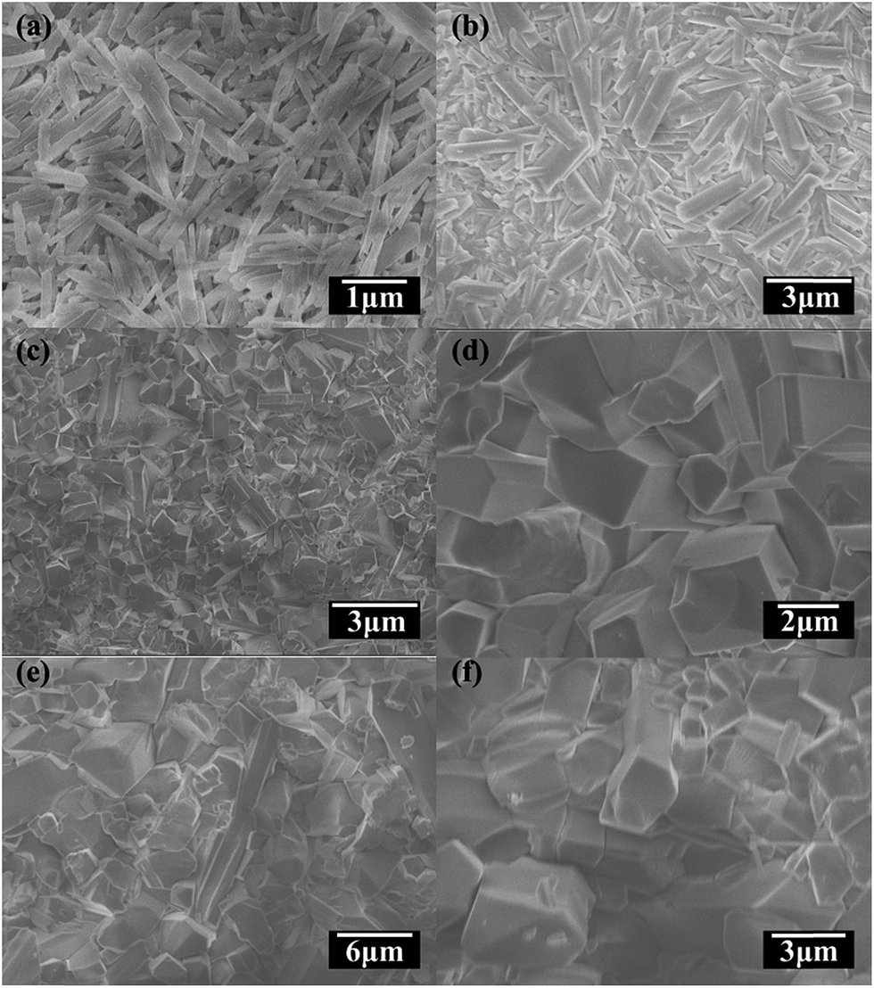 | ||
| Fig. 2 SEM images of: the top view of (a) F-03; (b) F-06, (c) F-07, (d) F-07(an enlarged view), (e) F-08 and (f) F-08 (an enlarged view). | ||
Gas separation of the MIL-120 membrane
Based on the successful synthesis of MIL-120 membrane, we tested the volumetric flow rates of the single gases H2, CO2, CH4 and N2 as well as the binary gases of H2/CO2, H2/CH4 and H2/N2 to study the gas permeability and selectivity of the membrane. The test results are summarized in Table S1.† As shown in Table S1,† the ideal separation factors, determined as the ratio of the single component permeances, are much higher than the Knudsen constant, which indicates a good quality of the membrane. Fig. 3a represents the permeances and separation factors at room temperature (293 K). It is found that the permeances show a decreasing trend in an order H2 > CH4 ≈ N2 > CO2 for both single- and binary-gas permeation and the permeance of H2 is much higher than those of the other gases. The mixture separation factors of H2/CO2, H2/CH4 and H2/N2 are 9.4, 7.9, and 7.3 respectively (at 293 K and 1 bar) with average H2 permeance of 3.5 × 10⁻⁷ mol m−2 s−1 Pa−1. These values are among the moderate H2 separation performance of reported MOF membranes. According to the review reported by Qiu15 in 2014, the separation factors of MOF membrane for H2–CO2, H2–CH4 and H2–N2 separations vary in the range from 4 to 30.9, 2 to 20.7, and 2.5 to 23.9 respectively and the H2 permeance ranges from 6.88 × 10⁻⁹ to 1.0 × 10⁻⁵ mol m−2 s−1 Pa−1. In comparison, Caro et al.28 reported a comparable H2/CO2 separation factor of 8.4 for a supported ZIF-7 membrane but relatively low fluxes (9.0 × 10⁻⁹ mol m−2 s−1 Pa−1). | ||
Fig. 3 (a) Permeances of single gases (squares) and the volume ratio 1![[thin space (1/6-em)]](https://www.rsc.org/images/entities/char_2009.gif) :1 binary gases as a function of molecular kinetic diameters (inset: the separation factor for H2 over other gases by binary gases tests); (b) Plot of H2/CO2, H2/N2 and H2/CH4 separation factors of the MIL-120 membrane at different test time (average values of five different membranes). Permeation temperature = 293 K, Feed pressure = 1 bar (inverted triangle: H2/CO2, triangles: H2/N2, circles: H2/CH4). :1 binary gases as a function of molecular kinetic diameters (inset: the separation factor for H2 over other gases by binary gases tests); (b) Plot of H2/CO2, H2/N2 and H2/CH4 separation factors of the MIL-120 membrane at different test time (average values of five different membranes). Permeation temperature = 293 K, Feed pressure = 1 bar (inverted triangle: H2/CO2, triangles: H2/N2, circles: H2/CH4). | ||
Thermal stability of the MIL-120 membrane (Fig. S3†) and its performance of gas permeability and selectivity under 313 K and 343 K (Table S1, Fig. S4†) were also tested.
We speculate the separation mechanism should be surface diffusion which means the permeance is governed by both diffusion and adsorption. Specifically, the H2 molecules diffuse through the MIL-120 membrane more easily due to their smallest molecule size, lowest molecular weight and the weakest interaction with the inner surface of the MIL-120 membrane which is shown by the heat of adsorption of gases on MIL-120 crystals in the order H2<N2< CH4<CO2 (Fig. S5† cited from literature25). By contrast CO2 molecule is larger and heavier with higher adsorption heat compared with other three kinds of gases so its permeance is lowest. Accordingly the separation factor of H2/CO2 is bigger compared with those of H2/CH4 and H2/N2.
The reproducibility and durability of the membranes are important parameters for practical application. As shown in Fig. 3b, the membrane retains high separation factors over 30 hours with small fluctuation. Moreover under ambient conditions, the membrane displays steady separation performance for more than three months which means that the membrane has high mechanical stability and a broad application prospect.
Conclusion
In conclusion through a range of experiments we got the optimal synthesis conditions and successfully obtained continuous and compact MIL-120 membranes on the surface of a-Al2O3 hollow ceramic fibers. We realize that the in situ seeding step is of great significance which serves the problem of the poor heterogeneous nucleation of MOF crystals on the substrate surface and avoids the complicated seed-coating step at the same time. The MIL-120 membrane exhibits moderate H2 separation performance and high thermal stability and durability.Acknowledgements
We are grateful to the financial support from Youth Science Fund Program of Qiqihar Medical University (grant no. QY2015Q-02), and Natural Science Foundation of Heilongjiang Province, China (grant no. B201110).Notes and references
- H. Li, M. Eddaoudi, M. O'Keeffe and O. M. Yaghi, Nature, 1999, 402, 276–279 CrossRef CAS.
- M. Dinca, A. F. Yu and J. R. Long, J. Am. Chem. Soc., 2006, 128, 8904–8913 CrossRef CAS PubMed.
- L. J. Murray, M. Dincă and J. R. Long, Chem. Soc. Rev., 2009, 38, 1294–1314 RSC.
- A. Huang, W. Dou and J. r. Caro, J. Am. Chem. Soc., 2010, 132, 15562–15564 CrossRef CAS PubMed.
- H. Bux, F. Liang, Y. Li, J. Cravillon, M. Wiebcke and J. r. Caro, J. Am. Chem. Soc., 2009, 131, 16000–16001 CrossRef CAS PubMed.
- H. Bux, C. Chmelik, J. M. van Baten, R. Krishna and J. Caro, Adv. Mater., 2010, 22, 4741–4743 CrossRef CAS PubMed.
- A. Huang, H. Bux, F. Steinbach and J. Caro, Angew. Chem., 2010, 122, 5078–5081 CrossRef.
- L. Ma, C. Abney and W. Lin, Chem. Soc. Rev., 2009, 38, 1248–1256 RSC.
- J. Lee, O. K. Farha, J. Roberts, K. A. Scheidt, S. T. Nguyen and J. T. Hupp, Chem. Soc. Rev., 2009, 38, 1450–1459 RSC.
- Y. Liu, Z. Ng, E. A. Khan, H.-K. Jeong, C.-b. Ching and Z. Lai, Microporous Mesoporous Mater., 2009, 118, 296–301 CrossRef CAS.
- Y. Liu, E. Hu, E. A. Khan and Z. Lai, J. Membr. Sci., 2010, 353, 36–40 CrossRef CAS.
- F. Zhang, X. Zou, X. Gao, S. Fan, F. Sun, H. Ren and G. Zhu, Adv. Funct. Mater., 2012, 22, 3583–3590 CrossRef CAS.
- R. Ranjan and M. Tsapatsis, Chem. Mater., 2009, 21, 4920–4924 CrossRef CAS.
- H. Guo, Y. Zhu, S. Qiu, J. A. Lercher and H. Zhang, Adv. Mater., 2010, 22, 4190–4192 CrossRef CAS PubMed.
- S. Qiu, M. Xue and G. Zhu, Chem. Soc. Rev., 2014, 43, 6116–6140 RSC.
- E. Biemmi, C. Scherb and T. Bein, J. Am. Chem. Soc., 2007, 129, 8054–8055 CrossRef CAS PubMed.
- S. Hermes, F. Schröder, R. Chelmowski, C. Wöll and R. A. Fischer, J. Am. Chem. Soc., 2005, 127, 13744–13745 CrossRef CAS PubMed.
- M. C. McCarthy, V. Varela-Guerrero, G. V. Barnett and H.-K. Jeong, Langmuir, 2010, 26, 14636–14641 CrossRef CAS PubMed.
- H. Guo, G. Zhu, I. J. Hewitt and S. Qiu, J. Am. Chem. Soc., 2009, 131, 1646–1647 CrossRef CAS PubMed.
- Y. S. Li, F. Y. Liang, H. Bux, A. Feldhoff, W. S. Yang and J. Caro, Angew. Chem., 2010, 122, 558–561 CrossRef.
- K. Tao, C. Kong and L. Chen, Chem. Eng. J., 2013, 220, 1–5 CrossRef CAS.
- K. Tao, L. Cao, Y. Lin, C. Kong and L. Chen, J. Mater. Chem. A, 2013, 1, 13046–13049 CAS.
- D. Jiang, A. D. Burrows, Y. Xiong and K. J. Edler, J. Mater. Chem. A, 2013, 1, 5497–5500 CAS.
- L. Fan, M. Xue, Z. Kang, H. Li and S. Qiu, J. Mater. Chem., 2012, 22, 25272–25276 RSC.
- C. Volkringer, T. Loiseau, M. Haouas, F. Taulelle, D. Popov, M. Burghammer, C. Riekel, C. Zlotea, F. Cuevas and M. Latroche, Chem. Mater., 2009, 21, 5783–5791 CrossRef CAS.
- S. Fan, F. Sun, J. Xie, J. Guo, L. Zhang, C. Wang, Q. Pan and G. Zhu, J. Mater. Chem. A, 2013, 1, 11438–11442 CAS.
- S. Fan, J. Liu, F. Zhang, S. Zhou and F. Sun, J. Mater. Res., 2013, 28, 1870–1876 CrossRef CAS.
- Y. S. Li, H. Bux, A. Feldhoff, G. L. Li, W. S. Yang and J. Caro, Adv. Mater., 2010, 22, 3322–3326 CrossRef CAS PubMed.
Footnote |
| † Electronic supplementary information (ESI) available: XRD pattern, table and figure of gas separation, TG curve, cited differential enthalpies of adsorption and isotherm. See DOI: 10.1039/c5ra09792d |
| This journal is © The Royal Society of Chemistry 2015 |