Bio-inspired laminated graphite nanosheets/copper composites

P. Wanga, W. Liua, L. Chen*a, C. Mub, G. Qib and F. Bian*c
aShanghai Hiwave Advanced Materials Technology Co., Ltd., Shanghai 200240, P. R. China. E-mail: lawson@wzhf.com; bianfenggang@sinap.ac.cn
bWenzhou Hongfeng Electrical Alloy Co., Ltd., Wenzhou 325603, P. R. China
cShanghai Synchrotron Radiation Facility, Shanghai Institute of Applied Physics Chinese Academy of Sciences, Shanghai 201204, P. R. China

Received 23rd May 2015 , Accepted 3rd June 2015

First published on 3rd June 2015


Abstract

As one of the most industrially important metals, copper (Cu) was successfully reinforced with graphite nanosheets (GNSs). A nacre-inspired laminated GNSs/Cu composite material was fabricated by a combination of ball-milling and hot-rolling techniques. During the ball-milling process, the GNSs were in situ produced from graphite exfoliation. The Cu–GNSs composite ingot was hot-rolled into a belt to form a laminated structure. The laminated Cu–GNSs composite material showed improved mechanical properties observed from tensile and three-point bending tests. The Young's modulus of Cu–GNSs composites was up to 170 GPa and the bending strength reached 660 MPa. This processing route was also advantageous in low-cost, mass-producing manufacture.

Introduction

Graphene (GR) is one atom thick, and shows extremely high strength and modulus which make it suitable as a reinforcing material.1–3 A number of polymer materials have been successfully reinforced by GR.4–6 For metal materials, some researchers have also reported the preparation of GR/metal composite materials.7,8 It seems that aluminium (Al) can be easily reinforced by GR, but for other metals, very few of them have been successful.9–13 Cu is one of the most industrially important metals, which requires improvement in mechanical properties for many applications, such as electrical contact materials, corrosion-resistant materials. Kim et al. used chemical vapour deposition (CVD) to produce GR and then transferred it onto the evaporated Cu thin film. Cu–GR composites consist of alternating nanolayers of Cu and GR. It is worth noting that the Cu–GR composites have an ultra-high compressive strength of 1.5 GPa. The disadvantage of this work is that the reported method is so complex and low-yield. Thus it is hard to apply it in commercial processes.14 Koltsova et al. also synthesized a few-layered graphene on the surface of micron-sized Cu powder using a CVD method, and the ethylene was used as the carbon source. The compacted Cu–GR composites showed an increase of 39% in hardness compared to pure Cu. Unfortunately, the comprehensive mechanical properties were not improved.15

The natural nacre of shellfish is well known for its laminated composite architecture, which provides shell with lightness, high strength and toughness. Learning from natural biological design is becoming a prevailing idea in developing new generation of metal-matrix composite materials, such as Cu, Al. Numerous nacre-inspired biomimetic materials have been reported and perform excellent properties.16–18 Those nacre-inspired laminated materials are mostly based on the combination of organic and inorganic materials to form the brick structure, which certainly coincide with those of natural nacre. In the field of metal matrix composite materials, the limitation of the conventional manufacturing process and the orientated dispersion of reinforcing material in metal matrices become the two main factors that delay the development of nacre-inspired biomimetic laminated metal composites. Nevertheless, some achievements have been made in carbon nanotube (CNTs)/metal laminated composites. Li et al. fabricated CNT/Cu laminated composites by combined techniques of cold rolling and annealing, using SWCNT films sandwiched between Cu thin foils.19 Kang et al. obtained a similar laminated microstructure by selective dip-coating of CNTs and Cu.20 Jiang et al. explored a “flake powder metallurgy” technique and successfully fabricated CNTs/Al biomimetic nanolaminated composites.21 All of the above reports showed positive results in reinforcement of metals. GR, with the inherent 2D structure and excellent mechanical properties, has the potential to be an ideal material fabricating biomimetic laminated metal composites. Numerous efforts have been made in GR/metal laminated composites, such as GR/Al, GR/Cu, GR/Ni, but so far there have been few achievements in this field.

In this study, a highly ordered laminated Cu–GNSs composite material was fabricated by the combination of ball-milling method and hot rolling technique. The GR were in situ exfoliated from graphite in the ball-milling process, in which simultaneously the Cu powder was processed into flakes. The compacted laminated GNSs and Cu composites ingot was forced to stack orderly by hot rolling. The laminated Cu–GNSs composites showed improved mechanical properties. This process routine was also advantageous in low-cost, mass-producing manufacture.

Experimental method

Flake graphite (XFNANO Co., China) and Cu powder (5–10 μm diameter, 99.99% in purity, GRINM Co., China) were added into pure alcohol (AR, Sinopharm Co., China). The weight ratio of graphite–Cu was set at 3 wt% and the ball-to-powder weight ratio was 20[thin space (1/6-em)]:[thin space (1/6-em)]1. The ball milling was conducted at a speed of 260 rpm min−1 for 10 hours. Take a small amount of sample every 5 h for test. The X-ray diffraction (XRD, RigakuD/max2550VL) and field emission scanning electron microscopy (Quanta 250, FEI) were employed to determine whether the graphite had been exfoliated into nanosheets and the Cu powder had been milled into flake.

The Cu–GNSs flake powder mixture were sealed in a mold. The mold was cold isostatic pressed at 100 MPa for 2 min. Then, we got a Cu–GNSs ingot with diameter of 40 mm and thickness of 10 mm. Under hydrogen condition, the ingot was heated for 5 hours at 850 °C. The Cu–GNSs ingot was embedded in a pure iron plate to avoid the oxidation of Cu. The iron plate was hot-rolled into a 0.6 mm strip as soon as it was heated to 750 °C. The iron coat was removed by immersing the plate in copper sulphate solution for 2 days. Finally, a Cu–GNSs strip with thickness of 0.4 mm was obtained. The process route is schematically illustrated in Fig. 1.


image file: c5ra09696k-f1.tif
Fig. 1 Schematic diagram of the process route for Cu–GNSs laminated composite material.

The fracture section was characterized by SEM equipped with an energy dispersive spectrometer (EDS). The Raman spectra were obtained from a Dispersive Raman Microscope (Senterra R200-L) with a 532 nm laser. The hardness was evaluated by a digital micro-hardness tester (MHV2000). The tensile and bending test were carried out on an electron universal testing machine controlled by a microcomputer (QJ210-1000N, Shanghai Qingji Testing Instruments CO., China) at room temperature. At least 5 specimens were tested. The tensile performance was measured at strain rate of 10 mm min−1 with a 25 mm gauge length of the specimens (0.40 ± 0.04 mm thickness, 11.0 ± 0.2 mm width). The bending strength was obtained by three point bending test according to the ref. 22. The specimens (2.0 ± 0.2 mm thickness, 24.0 ± 0.4 mm width) were bended to 45° with a 44.2 mm span at a speed of 10 mm min−1.

Results and discussion

The ball-milling process, is not only an effective way to produce flake metal powder, but also able to exfoliate graphite into few-layer graphene. Recently, flake powder metallurgy (FPM) technique has become a prevailing approach to fabricate metal/metal or metal/ceramic laminated materials.23–25 The FPM mainly based on the ball-milling, is meanwhile also an available method to exfoliate graphite onto few-layer graphene or graphite nanoplatelet. The Cu powder and graphite were mixed together and then suffered ball-milling. This process produced flake Cu powder, and on the other hand fabricated few-layer graphene. As shown in Fig. 2a, the as-prepared flake Cu–GNSs powder has a 2-D planar morphology. At large magnification, shown in Fig. 2b, it can be seen that the semi-transparent few-layer graphene with a diameter of 6–10 μm and a thickness of 5–10 nm.
image file: c5ra09696k-f2.tif
Fig. 2 SEM images of Cu–GNSs powder after 10 h ball-milling at (a) low and (b) large magnifications.

XRD results also demonstrated the exfoliation result of ball-milling process. The XRD patterns of raw Cu powder, graphite and resultant Cu–GNSs powder are shown in Fig. 3. It can be found that the (002) peak of graphite in Cu–GNSs sample is much weaker than that of raw graphite, indicating the decrease of graphite layers. The thickness of the GNSs was also evaluated by Scherrer equation which is widely used to evaluate the crystal size from XRD patterns. The equation is given by

 
L(002) = 0.89λ/(cos[thin space (1/6-em)]θ × FWHM) (1)
where L(002) is the thickness of the GNSs; λ is wavelength of incident X-ray; θ is diffraction angle and FWHM is full width at half maximum. The thickness of the GNSs was calculated in the order of 10 nm, corresponding to that obtained from SEM. The result is well consistent with previous work reported by Antisari et al.26 The low energy pure shear milling is an easy process of preparing graphite nanosheets which can well preserve the hexagonal crystal structure of graphite.


image file: c5ra09696k-f3.tif
Fig. 3 XRD patterns of Cu powder (raw material), graphite (raw material) and Cu–GNSs mixed powder after ball-milling.

The laminated structure of the hot-rolled resultant material was studied by SEM. The cross-section of Cu–GNSs composite belt is shown in Fig. 4a, in which the highly ordered layer-by-layer stacking can be seen. In order to further verify the distribution of GNSs in Cu matrix, elemental mapping of EDS was employed. Fig. 4b and c shows the distribution of the elements Cu and C, respectively. The results show that C is distributed uniformly, which probably indicates a good dispersion of graphene in matrix. The GNSs in Cu matrix can be verified in the magnified SEM (Fig. 4d) by spot-scanning EDS, and the corresponding results are shown in Fig. 4e. We can see the stagger arrangement of Cu and GNSs. As an additional explanation, the EDS of low-atomic-number materials, e.g. C, also contain the matrix information since the transmission of electrons through the low-atomic-number materials. Raman spectrum of Cu–GNSs composites further demonstrated the presence of GNSs in the composite material, shown in Fig. 4f. The density of Cu–GNSs composites is 8.46 g cm−3 and the theoretical density is 8.63 g cm−3, indicating the compactness of Cu–GNSs composites is 98%. High compactness is beneficial to improve the material performance.


image file: c5ra09696k-f4.tif
Fig. 4 (a) SEM of Cu–GNSs composites (cross-section) and the corresponding elemental mapping from EDS, indicating the distribution of Cu and C, and the corresponding results are shown in (b) Cu element and (c) C element. (d and e) The GNSs and Cu are distinguished by EDS at large magnifications. Two different spots 1 and 2 in (d) were chosen to obtain EDS and the corresponding results are presented in (e). (f) Raman spectrum of Cu–GNSs composites.

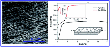
Tensile mechanical properties of pure Cu and Cu–GNSs composites are shown in Fig. 5a, and some relative works are shown in Table 1. The laminated Cu–GNSs composites exhibits a tensile strength of 330 MPa, approx. 69% higher than pure Cu (GB Cu). It is worth noting that the Young's modulus of laminated Cu–GNSs composites is as high as 170 GPa, which is much higher than those of reported ones. However, the laminated Cu–GNSs composites only has a ductility of 0.25%. Since the anisotropy of the structural units of the composite material, the performance in lateral and lengthways directions would have their own unique merits. In order to investigate the mechanical properties in lateral and lengthways directions of the composite strip, three-point bending and tensile tests were performed respectively. Typical load-deflection curves of Cu–GNSs composites and pure Cu are plotted in Fig. 5b. The bending strength and modulus were calculated from Fig. 5b according to the following equations:

 
σf = 3FL/2ah2 (2)
where σf is bending strength; L is the span; F is the maximum force; a is width and h is thickness.
 
Ef = L3s/4ah3 (3)
where Ef is bending flexible modulus; s is the elastic ratio defined by
 
s = FL (4)
where F is the loaded force and ΔL is deflection.


image file: c5ra09696k-f5.tif
Fig. 5 (a) Stress–strain curves of pure Cu and Cu–GNSs composites obtained from tensile test. The insert schematically illustrates the tensile test. (b) Load-deflection curves upon three-point bending in the lateral orientation. The insert schematically illustrates the three-point bending test.
Table 1 Comprehensive mechanical properties of pure Cu and Cu–GNSs composites
  Tensile strength (MPa) Young's modulus (GPa) Elongation (%) Hardness Reference
a Rolled, annealed and rolled Cu/SWCNT.b Fabricated by stacking layers of CNTs and layers of electroplated Cu matrix.c Fabricated by spark plasma sintering (SPS) of acid-treated and electroless coated MWCNTs by copper.d Fabricated by molecular-level mixing process and SPS.e Fabricated by combination of the ball milling and hot-pressing processing.f Fabricated by combination of ball milling and high-ratio differential speed rolling (HRDSR).g The GR–Ni hybrids were synthesized by an in situ chemical reduction method and then incorporated into the Cu matrix to fabricate bulk GR–Ni/Cu composites by SPS.h Cold rolled micron-sized copper powder coated with a few-layered GR by CVD.i Chinese standard code for a kind of half-hard Cu.
Cu–GR 330 170 0.25 115 (HV) This work
Rolled Cu 314 107 1.5 28
Cu–CNTa 361 132 0.3 28
Cu–CNTb 239.5 110.5 >1.2 20
Cu–CNTc 341.2 90 0.012 110 (HV) 27
Cu–GRd 284 131 ≈0.14 29
Cu–GRe 320 105 30
Cu–GRf 425.5 16.4 31
Cu–GRg 320 132 32
Cu–GRh 50 (HB) 15
Pure Cu ≈150 101 0.4 29
GB Cu ≥195 ≥30 ≤70 T2 (M)i


The results revealed that the laminated Cu–GNSs composite has a bending strength of 660 MPa and a modulus of 82.6 MPa, which are higher than those of pure Cu (bending strength 534 MPa, bending flexible modulus 60.4 MPa). Nevertheless, the bending test showed the extensive inelastic deformation of the laminated Cu–GNSs composite materials. The laminated Cu–GNSs composites also show a hardness of HV 115, which is close to that of Cu–CNTs laminated composite material.27

The unique mechanical properties of laminated Cu–GNSs composites may be caused by the resistance of dislocation motion of Cu in laminated structure. According to the dislocation theory, the inherent dislocation in Cu matrix formed in processing moves to the interface of Cu and GNSs layer during the initial deformation under shear stress. The dislocation would be stopped at the interface of Cu and GNSs layer so that the tensile strength and modulus are increased while the ductility is decreased. The schematic explanation is shown in Fig. 6. The stress concentration regions form at the edges of GNSs layer, since the poor interaction of Cu matrix and GNSs layers. The poor interaction also reduces the load-transfer capacity of GNSs layer in Cu matrix. The stress concentration regions and the low load-transfer capacity of GNSs result in the low ductility. Our future work will focus on the interface improvement of Cu and GNSs to promote the ductility of the laminated composite material. For bending mode, the laminated structure would probably facilitate in energy dissipation along the GNSs and Cu layers, similar to the mechanism of shell structure. Therefore, the laminated Cu–GNSs exhibited improved bending strength and modulus compared with pure Cu exfoliation of graphite into GNSs and flake-powder-metallurgy technique. As a result, the laminated Cu–GNSs composites demonstrated improved properties in bending and tensile tests. The dislocation motion was considered to be stopped at the interface of Cu and GNSs, which was the key point for the contribution of the reinforced mechanism of the laminated Cu–GNSs composites. This facile approach was expected to be extended for the other graphene-based metal composites with low-cost and high performance.


image file: c5ra09696k-f6.tif
Fig. 6 Schematic illustration of the reinforcing mechanism of laminated Cu–GNSs composite material.

Conclusion

In summary, a ball-milling and hot-rolling technique was developed for the fabrication of a highly ordered laminated Cu–GNSs composites. The process routine combined the advantage of in situ exfoliation of graphite into GNSs and flake-powder-metallurgy technique. As a result, the laminated Cu–GNSs composites demonstrated improved properties in bending and tensile tests. The dislocation motion was considered to be stopped at the interface of Cu and GNSs, which was the key point for the contribution of the reinforced mechanism of the laminated Cu–GNSs composites. This facile approach was expected to be extended for the other graphene-based metal composites with low-cost and high performance.

References

  1. X. Liu, Y. C. Fan, J. L. Li, L. J. Wang and W. Jiang, Adv. Eng. Mater., 2015, 17, 28–35 CrossRef CAS PubMed .
  2. J. N. Coleman, M. Lotya, A. O'Neill, S. D. Bergin, P. J. King, U. Khan, K. Young, A. Gaucher, S. De, R. J. Smith, I. V. Shvets, S. K. Arora, G. Stanton, H. Y. Kim, K. Lee, G. T. Kim, G. S. Duesberg, T. Hallam, J. J. Boland, J. J. Wang, J. F. Donegan, J. C. Grunlan, G. Moriarty, A. Shmeliov, R. J. Nicholls, J. M. Perkins, E. M. Grieveson, K. Theuwissen, D. W. McComb, P. D. Nellist and V. Nicolosi, Science, 2011, 331, 568–571 CrossRef CAS PubMed .
  3. R. Sengupta, M. Bhattacharya, S. Bandyopadhyay and A. K. Bhowmick, Prog. Polym. Sci., 2011, 36, 638–670 CrossRef CAS PubMed .
  4. J. Zhao, X. W. Wang, W. D. Zhou, E. J. Zhi, W. Zhang and J. H. Ji, J. Appl. Polym. Sci., 2013, 130, 3212–3220 CrossRef CAS PubMed .
  5. P. A. Song, Z. G. Xu and Q. P. Guo, ACS Macro Lett., 2013, 2, 1100–1104 CrossRef CAS .
  6. P. A. Song, L. N. Liu, G. B. Huang, Y. M. Yu and Q. P. Guo, Nanotechnology, 2013, 24, 505706 CrossRef PubMed .
  7. I. A. Ovid'ko, Rev. Adv. Mater. Sci., 2014, 38, 190–200 Search PubMed .
  8. D. Lin, C. R. Liu and G. J. Cheng, Acta Mater., 2014, 80, 183–193 CrossRef CAS PubMed .
  9. S. E. Shin, H. J. Choi, J. H. Shin and D. H. Bae, Carbon, 2015, 82, 143–151 CrossRef CAS PubMed .
  10. S. J. Yan, S. L. Dai, X. Y. Zhang, C. Yang, Q. H. Hong, J. Z. Chen and Z. M. Lin, Mater. Sci. Eng., A, 2014, 612, 440–444 CrossRef CAS PubMed .
  11. Y. Huang, Q. B. Ouyang, D. Zhang, J. Zhu, R. X. Li and H. Yu, Acta Metall. Sin., 2014, 27, 775–786 CrossRef CAS .
  12. M. X. Li, H. W. Che, X. Y. Liu, S. X. Liang and H. L. Xie, J. Mater. Sci., 2014, 49, 3725–3731 CrossRef CAS .
  13. Y. Cui, L. D. Wang, B. Li, G. J. Cao and W. D. Fei, Acta Metall. Sin., 2014, 27, 937–943 CrossRef CAS .
  14. Y. Kim, J. Lee, M. S. Yeom, J. W. Shin, H. Kim, Y. Cui, J. W. Kysar, J. Hone, Y. Jung, S. Jeon and S. M. Han, Nat. Commun., 2013, 4, 1–7 Search PubMed .
  15. T. S. Koltsova, L. I. Nasibulina, I. V. Anoshkin, V. V. Mishin, E. I. Kauppinen, O. V. Tolochko and A. G. Nasibulin, J. Mater. Sci. Eng. B, 2012, 2, 240–246 CAS .
  16. L. P. Xu, J. T. Peng, Y. B. Liu, Y. Q. Wen, X. J. Zhang, L. Jiang and S. T. Wang, ACS Nano, 2013, 7, 5077–5083 CrossRef CAS PubMed .
  17. P. Das, S. Schipmann, J. M. Malho, B. L. Zhu, U. Klemradt and A. Walther, ACS Appl. Mater. Interfaces, 2013, 5, 3738–3747 CAS .
  18. S. Askarinejad and N. Rahbar, J. R. Soc., Interface, 2015, 12, 1–13 Search PubMed .
  19. Y. H. Li, W. Housten, Y. M. Zhao and Y. Q. Zhu, Nanotechnology, 2007, 18, 1–6 Search PubMed .
  20. T. J. Kang, J. W. Yoon, D. I. Kim, S. S. Kum, Y. H. Huh, J. H. Hahn, S. H. Moon, H. Y. Lee and Y. H. Kim, Adv. Mater., 2007, 19, 427 CrossRef CAS PubMed .
  21. L. Jiang, Z. Q. Li, G. L. Fan, L. L. Cao and D. Zhang, Scr. Mater., 2012, 66, 331–334 CrossRef CAS PubMed .
  22. R. Wang, Z. Suo, A. Evans, N. Yao and I. Aksay, J. Mater. Res., 2001, 16, 2485–2493 CrossRef CAS .
  23. H. A. Hassan and J. J. Lewandowski, Scr. Mater., 2009, 61, 1072–1074 CrossRef CAS PubMed .
  24. W. L. Zhang, Z. Q. Li, L. Jiang, X. Z. Kai, X. Y. Dai, G. L. Fan, Q. Guo, D. B. Xiong, Y. S. Su and D. Zhang, Mater. Sci. Eng., A, 2014, 594, 324–329 CrossRef CAS PubMed .
  25. L. Jiang, Z. Q. Li, G. L. Fan and D. Zhang, Scr. Mater., 2011, 65, 412–415 CrossRef CAS PubMed .
  26. M. V. Antisari, A. Montone, N. Jovic, E. Piscopiello, C. Alvani and L. Pilloni, Scr. Mater., 2006, 55, 1047–1050 CrossRef CAS PubMed .
  27. W. M. Daoush, B. K. Lim, C. B. Mo, D. H. Nam and S. H. Hong, Mater. Sci. Eng., A, 2009, 513, 247–253 CrossRef PubMed .
  28. Y.-H. Li, W. Housten, Y. Zhao and Y. Q. Zhu, Nanotechnology, 2007, 18, 205607 CrossRef .
  29. J. Hwang, T. Yoon, S. H. Jin, J. Lee, T. S. Kim, S. H. Hong and S. Jeon, Adv. Mater., 2013, 25, 6724–6729 CrossRef CAS PubMed .
  30. K. Chu and C. C. Jia, Phys. Status Solidi A, 2014, 211, 184–190 CrossRef CAS PubMed .
  31. W. J. Kim, T. J. Lee and S. H. Han, Carbon, 2014, 69, 55–65 CrossRef CAS PubMed .
  32. Y. X. Tang, X. M. Yang, R. R. Wang and M. X. Li, Mater. Sci. Eng., A, 2014, 599, 247–254 CrossRef CAS PubMed .

This journal is © The Royal Society of Chemistry 2015
Click here to see how this site uses Cookies. View our privacy policy here.