
Effect of fixed carbon molecular sieve (CMS) loading and various di-ethanolamine (DEA) concentrations on the performance of a mixed matrix membrane for CO2/CH4 separation
Rizwan Nasira,
Hilmi Mukhtar*b,
Zakaria Manc,
Maizatul Shima Shaharund and
Mohamad Zailani Abu Bakare
aDepartment of Chemical Engineering, Universiti Teknologi PETRONAS, 32610 Bandar Seri Iskandar, Perak Darul Ridzuan, Malaysia. E-mail: rizwan.rai@gmail.com
bDepartment of Chemical Engineering, Universiti Teknologi PETRONAS, 32610 Bandar Seri Iskandar, Perak Darul Ridzuan, Malaysia. E-mail: hilmi_mukhtar@petronas.com.my; Tel: +6053688686
cDepartment of Chemical Engineering, Universiti Teknologi PETRONAS, 32610 Bandar Seri Iskandar, Perak Darul Ridzuan, Malaysia. E-mail: zakaman@petronas.com.my
dDepartment of Fundamental and Applied Science, Universiti Teknologi PETRONAS, 32610 Bandar Seri Iskandar, Perak Darul Ridzuan, Malaysia. E-mail: maizats@petronas.com.my
eSchool of Chemical Engineering, Universiti Sains Malaysia, 11800 USM, Pulau Penang, Malaysia. E-mail: chmohdz@usm.my
First published on 29th June 2015
Abstract
Polyethersulfone (PES) as a polymer along with carbon molecular sieves (CMS) as an inorganic filler and di-ethanolamine (DEA) as the third component were used to fabricate amine mixed matrix membranes (A3Ms). The CMS and the developed membranes were characterized by variable pressure field emission scanning electron microscopy (VPFESEM) and thermal gravimetric analysis (TGA). FESEM micrographs showed that with the addition of DEA, uniform distribution of CMS particles in the PES matrix was achieved with good polymer-filler contact. The combined effect of DEA concentration (5–15 wt%), feed pressure (2–10 bar) and CMS loading on the CO2/CH4 transport properties of the PES–CMS–DEA membranes were studied. The results revealed that the PES–CMS–DEA (15 wt% DEA) membrane showed a CO2 permeance of 123.49 GPU at 2 bar, which is more than a threefold increment with respect to the native PES membrane. The corresponding CO2/CH4 ideal selectivity was increased from 5.40 for PES to 51.39 for PES–CMS–DEA (15 wt% DEA). The CO2 permeance of the PES–CMS–DEA (A3Ms) membranes was higher than PES membranes over the operating pressure range.
1 Introduction
CO2/CH4 separation has much potential to be employed in many industrial applications like biogas upgrading, enhanced oil recovery,1 natural gas treatment and landfill gas treatment.2,3 It was reported that natural gas usually consists of up to 80% impurities, depending on sources.4,5 Acid gas contents could reach and even overpass 50% volume in some unconventional natural gas streams.6 The most common contaminant in natural gas is CO2 therefore, the removal of CO2 is very important. Generally, pipeline specifications for natural gas require a CO2 concentration to be below 2–3%. Moreover, the CO2 removal will also increase the calorific value and transportability of natural gas.7Gas separation through membranes is likely to play a progressive vital role to minimize industrial process cost and the environmental impact. Membrane technology offers a number of advantages over other technologies for gas separation. Conventional technologies such as, cryogenic distillation, amine absorption and adsorption are used to remove acid gases i.e. carbon dioxide from natural gas. The phase change adds a significant energy cost to the separation cost. Membrane gas separation does not require a phase change. Moreover, gas separation membrane units are small in size as compared to other separation plants.8
A wide range of materials is employed for the synthesis of membranes; glassy polymers are the most widely used materials. The variety of materials makes membranes applicable in a wide range of industrial separation processes, including air separation, hydrogen recovery, natural gas processing and light gas separations.3,9 Polymeric membranes offer many desired properties including low operating cost and ease of construction and excellent processability. Polymeric membranes, due to the trade-off relationship between selectivities and permeabilities generally experience an upper bound limitation.1 This upper bound for various binary gas pairs was first suggested by Robeson in 1991.10 Inorganic membranes provide substantial discrimination based on size or shape of gas molecules by allowing some of component gases to specially pass through.11 The properties of inorganic membranes such as high thermal and chemical stability, high mechanical strength as well as their high separation performances, make them exceptionally good candidates for harsh operational conditions. However, the development of molecular sieve membranes consist of large surface areas for commercial exploitation is laborious and costly, thus hindering its large-scale industrial applications.12
The mixed-matrix membrane (MMMs) is a new membrane material for gas separation and plays a vital role in the advancement of current membrane-based separation technology.13 Mixed matrix membranes (MMMs) with hybrid characteristics were developed as an alternative approach to overcome the above mentioned limitations of polymeric and inorganic membranes. They exhibit the excellent gas separation properties of inorganic materials and combine desirable mechanical properties with the economical processing capacity of polymers.13,14 Although, the performance of MMMs is superior to polymeric and inorganic membranes, but these membranes also exhibit some limitations like poor polymer – sieve contact, agglomeration of particles, non-uniform distribution of particles.13,15 G. Dong et al. reviewed several developed strategies to minimize the limitation of mixed matrix membranes.16 Previously, the researchers reported another approach to improve the structure of MMMs by incorporating the third component in the space between the filler/polymer phases to interact with both phases. Usually, low molecular weight additives are used as the third component to fill the non-selective voids and improve the filler/polymer compatibility.17–19 These studies revealed that the due to elimination of voids the performance of MMMs was improved.
The recent study using the ionic liquid (1-ethyl-3 methylimidazolium bis(trifluoromethylsulfonyl)imide, emim(Tf2N)) into MMMs was carried out by D. F. Mohshim et al.20 They fabricated PES/SAPO-34 (20 wt%)/emim(Tf2N) (5–20 wt%) membranes. CO2 permeance and CO2/CH4 selectivity were enhanced by the addition of different concentration of emim(Tf2N) compared to PES/SAPO-34 membranes. But, they observed the agglomeration of SAPO-34 particles.
The selections of materials remain as the heart of MMMs fabrication. PES was selected as the membrane polymer in this study. The repeating unit in the structure of PES possesses a certain degree of rigidity. It has a glass transition temperature of 225 °C.21 CMS is widely used for gas separation due to its porous property.22,23 The incorporation of CMS lends a higher permeability to MMMs due to a higher degree of porosity and fine pore size distribution. Moreover, the size of pore opening of CMS is of the same order as the size of gas molecules, thus allowing precise discrimination of certain gas species.16 DEA is the most extensively used secondary amine for the removal of acid gases, due to favorable reaction kinetics, stability and rapid formation of carbamates while reacting with CO2.24 It is also resistant to solvent degradation25 and has less vapor pressure than primary alkanolamines.26 A number of studies consisting of secondary alkanolamines have been reported and evaluated for CO2/CH4![[thin space (1/6-em)]](https://www.rsc.org/images/entities/char_2009.gif) 27,28 and CO2/N224 separation. Thus, DEA is emerged as a preferred choice to enhance the performance of gas separation membranes when applied for acid gas purification.
27,28 and CO2/N224 separation. Thus, DEA is emerged as a preferred choice to enhance the performance of gas separation membranes when applied for acid gas purification.
In the present study, CMS and DEA were incorporated into the PES matrix to develop amine mixed matrix membrane to enhance the CO2 separation. The DEA was selected due to its excellent affinity with CO2, which can facilitate the transport of CO2 molecules through membranes. Moreover, it acts as a third component to improve the morphology of membranes. Due to combined effect of CMS and DEA results in higher CO2 permeance are accepted. The filler and prepared membranes were characterized by FTIR, FESEM and TGA. Further investigations were performed to evaluate the effect of DEA concentration, feed pressure on CO2/CH4 transport properties of MMMs. Finally, the performance of developed membranes was compared with other selected MMMs.
2 Experimental
2.1 Materials
ULTRASON E6020P®, as a commercial polyethersulfone (PES) with good thermal and mechanical properties, was purchased from BASF chemicals Germany. Carbon molecular sieve (CMS) extruded pellets of cylindrical shape were supplied by Japan Enviro Chemical. CMS has a uniform pore size on the surface and interconnected channels that enables fast transport of gas molecules.29 The porous nature of CMS provides the justification of high productivity. CMS has selective micro pore is less than 4 Å.30,31 N-methyl-2-pyrrolidinone (NMP) (C5H9NO bp 202 °C, >99.9% pure), was supplied by Merck (Germany) and used without further treatment. Test gases (CH4 and CO2 > 99.9%) were purchased from Gas walkers Sdn. Bhd Malaysia.2.2 Synthesis of membranes
In this study the total of five (05) membranes which are pure PES, PES–CMS (30 wt%) and PES–CMS–DEA (5–15 wt%) were developed for the separation of CO2 from CH4. Table 1 shows the dope solution compositions for all membranes. As for as pretreatment of materials is concern, the PES flakes and CMS powder were dried overnight at 100 °C in an oven.| Sample name | PES (wt%) | CMS (wt%) | DEA (wt%) |
|---|---|---|---|
| M-1 | 20 | — | — |
| M-2 | 20 | 30 | — |
| M-3 | 20 | 30 | 5 |
| M-4 | 20 | 30 | 10 |
| M-5 | 20 | 30 | 15 |
 | ||
| Fig. 1 Visualization of PES–CMS–DEA amine mixed matrix membrane. | ||
2.3 Supplementary characterization
Variable pressure field emission scanning electron microscope (VPFESEM, Zeiss Supra55 VP) was used to observe the cross-sectional morphology of the membranes and CMS particles. Generally, the FESEM is used for conductive and non-conductive materials. However, for conductive materials, the FESEM operates at vacuumed condition while for non-conductive materials it operates at variable pressure. Since the developed membranes are non-conductive materials, VPFESEM is used in this study. The pressure is automatically varied within the system by this equipment. All membranes were fractured using liquid nitrogen before scanning. Thermal stability of membranes was investigated by Thermogravimetric Analyzer (TGA, Perkin Elmer Simultaneous Analyzer STA 6000) from 25 °C to 800 °C with a heating rate of 10 °C min−1 under N2 atmosphere. The carbon, nitrogen and sulphur components were investigated by Elementar Vario MICRO CUBE. The instrument has carbon, hydrogen, nitrogen and sulphur detectors. Approximately 2 mg of homogenous solid samples are placed in instrument holder. CHN analysis is accomplished by combustion analysis.2.4 Gas permeation analysis
The gas permeance of membranes was measured by the permeation measurement equipment described in the previous literature.20 The gas permeation experiments were carried out according to the method used by the previous studies.20,32,33 The membrane sample was placed in the membrane unit, which was supported by polypropylene perforated circular sheet and a mesh. The cell was also sealed with O-ring seals to prevent the gas leakage from the module. The system was also equipped with some more components like pressure gauges, gas flow meters, Swagelok® fittings and valves. The feed side pressure should be maintained. Prior to performing the test, the system was vacuumed for 30 minutes to remove the remaining gases and impurities trapped in the unit. The flow rate of permeate side was measured by the bubble flow meter. The feed gas was supplied directly from the gas cylinders. The feed stream pressure was measured with the help of pressure gauge. Supply of gas was controlled by the three way valve, which allowed only one gas to enter into the system at one time. The permeate side pressure was assumed to be at atmospheric pressure. The permeate flow rate was recorded at every 15–20 minutes for 3–5 times. Moreover, pure gas (CO2 and CH4) permeability results were recorded at steady state conditions and were obtained from the average value of at least 2 times measurement for each membrane. The permeance was calculated by the following equation:
 | (1) |
 | (2) |
The schematic drawing of the membrane module is shown in Fig. 2. It consists of a stainless disk circular steel membrane cell having the area of 17 cm2.
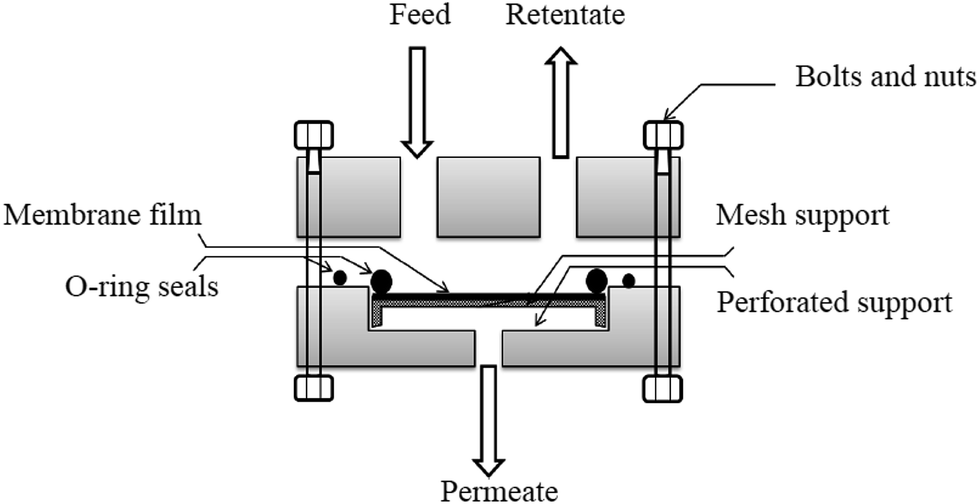 | ||
| Fig. 2 Schematic of the membrane module. | ||
3 Results and discussion
3.1 CMS characterization
The FESEM micrograph of CMS powder is shown in Fig. 3. It is observed that the grinded CMS particles have non-uniform size and different shapes. The micrographs confirmed that CMS powder has a wide range of particles size. The different size, non-uniform shape, and agglomeration were due to the grinding process. The agglomeration of small particles was the main reason of non-uniform shape and size. There are several key aspects relating to the formation of aggregates and agglomerates such as during impact and friction, the CMS particles absorb a certain amount of energy; this energy raises their surface energy, and they become unstable.34 It was also reported in the previous published literature that grinding is a powerful technique to obtain the desired size and shape of the particles.35,36 Fig. 4 shows the particle size distribution of CMS particles. The distribution was found in the range of 0.20 ± 0.2 to 3.0 ± 0.5 μm. This broad range of particles size has been obtained due to grinding.37 | ||
| Fig. 3 FESEM micrograph of CMS particles. | ||
 | ||
| Fig. 4 Particle size distribution of CMS particles. | ||
3.2 Membrane characterization
 | ||
| Fig. 5 FESEM micrographs of (a), pure PES (M-1), (b) PES–CMS (M-2), (c) PES–CMS–DEA 5% (M-3), (d) PES–CMS–DEA 10% (M-4) and (e) PES–CMS–DEA 15% (M-5) (magnification 500×). | ||
Fig. 5(c–e) show the FESEM images of PES–CMS–DEA amine mixed matrix membranes with fixed loading (30 wt%) of CMS and various concentrations (5–15 wt%) of DEA. The membranes have dense and no pores structures were observed at these magnifications. The developed membranes have the thickness of 105.2 μm, 49.36 μm and 85.99 μm for PES/30% CMS/5% DEA (M-3), PES/30% CMS/10% DEA (M-4) and PES/30% CMS/15% DEA (M-5) respectively. It has been found that the homogeneity of CMS particles in PES matrix was enhanced enough without forming the agglomerates. As Fig. 5(b) revealed that at higher loading of CMS particles some of the dense regions appear in the membranes. However, interestingly the dense regions have been disappeared by the addition of DEA in the membranes.
In addition, relative to PES–CMS (30%) MMMs, the dense regions were reduced to some extent. In addition, with the increase in DEA loading from 5% to 15%, the voids were eliminated further. Thus, the incorporation of DEA can enhance the compatibility between CMS and polymer. Same observation has been studied by Elif Karatay et al. (2010) when they fabricated the PES/SAPO-34/HMA MMMs.17
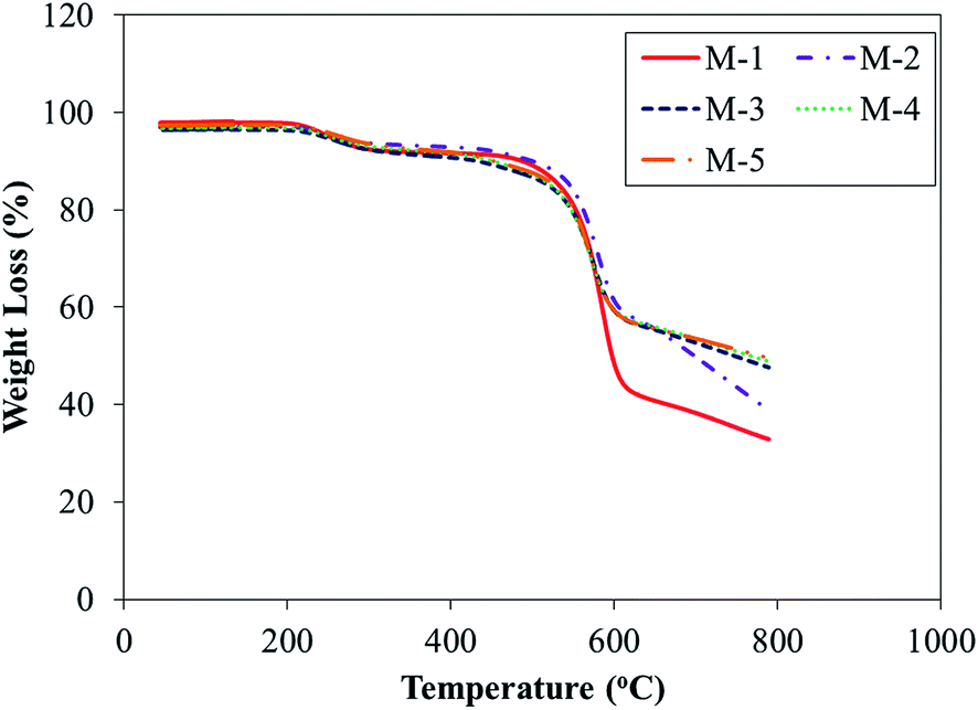 | ||
| Fig. 6 TGA thermograms of pure PES (M-1), PES–CMS (M-2), PES–CMS–DEA 5% (M-3), PES–CMS–DEA 10% (M-4) and PES–CMS–DEA 15% (M-5) membranes. | ||
Fig. 6 also shows the weight loss of PES–CMS (M-2), PES–CMS–DEA 5% (M-3), PES–CMS–DEA 10% (M-4) and PES–CMS–DEA 15% (M-5). It is also observed that TGA curve of each membrane has two thermal events, the first event at about 200–310 ± 2 °C and the second major event at 415–620 ± 2 °C. These are attributed to evaporation of the adsorbed solvent within the membranes and the thermal decomposition of the polymer respectively. The residual weights of PES, PES–CMS and PES–CMS–DEA membranes with 30 wt% filler loadings and 5–15 wt% addition of DEA at 800 °C, are 33.60, 40.08, 48.19, 49.72 and 50.11%, respectively. The increasing trend of residual weight is attributed to the interaction of CMS and DEA with polymer matrix33 and confirms the higher thermal stability of the fabricated membranes1 in comparison with the neat PES membrane. The comparison of total amounts of weight loss for PES–CMS and PES–CMS–DEA membranes is shown in Table 2. It is observed that the total amounts of weight loss for PES–CMS–DEA (M-3 to M-5) are about 1% higher than the loss for PES–CMS (M-2) membrane which may be related to some loss of DEA.
| Membranes | Weight loss between 200–300 °C (%) | Weight loss between 415–620 °C (%) | Total weight loss (%) |
|---|---|---|---|
| M-2 | 2.61 | 32.39 | 35.00 |
| M-3 | 3.69 | 31.65 | 35.30 |
| M-4 | 3.70 | 31.73 | 35.43 |
| M-5 | 3.84 | 32.86 | 36.70 |
3.3 Carbon–nitrogen–sulphur elemental analysis
Carbon–nitrogen–sulphur (CNS) elemental analysis performed for PES, PES–CMS, and PES–CMS–DEA membranes. The results are tabulated in Table 3 are the average of three measurements.| Membrane | % C | % N | % H | % S |
|---|---|---|---|---|
| M-1 | 60.95 | 1.14 | 3.79 | 13.10 |
| M-3 | 66.98 | 1.42 | 3.32 | 9.99 |
| M-4 | 66.97 | 1.40 | 3.31 | 9.88 |
| M-5 | 96.56 | 2.25 | 4.88 | 14.37 |
DEA and NMP are the only compounds having nitrogen element in the membranes. Therefore, the increase percentage of nitrogen amount can be attributed to the presence of DEA in the membranes. Table 3 also shows that the carbon and hydrogen percentages detected are also increased by the adding of different concentration of DEA. In addition in M-4 amounts of nitrogen, carbon and hydrogen element is reduced. It may be due to the escaping of DEA from the membranes matrix during solvent evaporation step. Thus, the results shows that the DEA is present in the membranes and which effecting the gas separation performance of the PES–CMS–DEA membranes as mentioned in the next section.
3.4 Gas permeation study
 | ||
| Fig. 7 Effect of DEA concentration on the CO2 and CH4 permeance at 6 bar pressure. | ||
 | ||
| Fig. 8 Effect of DEA concentration on CO2/CH4 selectivity. | ||
Fig. 8 shows the ideal gas selectivity of industrially important gas pair i.e. CO2/CH4, where substantial enhancements were observed with increasing DEA concentration. The increasing trend of selectivity is due to DEA concentration and CMS loading. The native PES CO2/CH4 selectivity of 10.94 was increased to 15.63, 21.65 and 38.16. The overall percent increase in selectivities is approximately 248.81% as compared to the PES–CMS MMM (M-2) membrane. The addition of DEA enhanced the selectivities of gas pairs having larger size different between the gases. The DEA increased the diffusion selectivity of the PES–DEA–CMS membranes.
The similar study using the ionic liquid (1-ethyl-3-methylimidazolium bis(trifluoromethylsulfonyl)imide, emim(Tf2N)) into MMMs was carried out by D. F. Mohshim et al.20 They fabricated PES/SAPO-34 (20 wt%)/emim(Tf2N) (5–20 wt%) membranes. CO2 permeance and CO2/CH4 selectivity were enhanced by the addition of different concentration of emim(Tf2N) compared to PES/SAPO-34 membranes at high pressure. As the current results show that with the addition of DEA at each concentration, both permeance and selectivity were improved. The difference in permeance values is due to the operating pressure. These results might stem from the combined effect of DEA and CMS. Furthermore, the cited literature showed the decreasing trend of permeance and increasing trend of selectivity respectively with the increase of pressure. Similar trend has been observed in present work.
 | ||
| Fig. 9 Effect of pressure on the CO2 and CH4 permeance of pure PES (M-1), PES–CMS (M-2), PES–CMS–DEA 5% (M-3), PES–CMS–DEA 10% (M-4) and PES–CMS–DEA 15% (M-5) membranes. | ||
 | ||
| Fig. 10 Effect of pressure on the selectivity of pure PES (M-1), PES–CMS (M-2), PES–CMS–DEA 5% (M-3), PES–CMS–DEA 10% (M-4) and PES–CMS–DEA 15% (M-5) membranes. | ||
Fig. 10 reveals that as the pressure increases, the ideal selectivity also increased significantly from 3.08 to 5.40 in M-1, 10.33 to 11.11 for M-2 11.98 to 18.12 for M-3, 14.18 to 21.71 for M-4 and 23.24 to 51.39 for M-5. The increase of selectivity with the increase of pressure is due to absences of plasticization phenomena because this study was carried out at 2–10 bars pressure, which is lower than plasticization pressure of PES. As pressure passes the specific pressure named as plasticization pressure, the performance of membrane declines such that increase in permeance and decrease in selectivity is observed.48,49 The substantial increase is observed in M-5 was due to the higher concentration of DEA (15 wt%). It should be noticed that amine are the facilitated factor for CO2 transport through membrane. Hence, the higher concentration of DEA will definitely increase the CO2 permeance. However, the DEA is not selective towards the CH4 as shown in Fig. 9. Thus, the selectivity increased accordingly. Moreover, the increasing trend of ideal selectivity is firstly due to high solubility of CO2 as compared to the CH4 in DEA. Secondly, when pressure increased then the free volume is decreased so due to bigger kinetic diameter of CH4 the permeance of CH4 reduced. Therefore, selectivity increased.20
These findings are in good agreement with dual sorption model studied by Paul and Koros.50 Similar results have been reported in different studies.20,51–54 Similarly, Peydayesh et al.55 reported analogous results for SAPO–34/Matrimid® 5218 mixed matrix membrane and Wiryoatmojo A. S. et al.56 for PSU–CMS mixed matrix membranes. It shows the combined effect of CMS and DEA addition on permeance and selectivity, and reveals that the M-3, M-4, and M-5 amine MMM have superior gas permeation than M-1and M-2.
3.5 Separation performance of developed membranes on Robeson bound
The CO2/CH4 separation performances of all developed membranes are shown in Fig. 11 relative to the Robeson's57 upper bound graph at pressure of 10 bar. It is revealed that the CO2 permeability and CO2/CH4 selectivity are increased instantaneously by adding DEA and CMS and are able to overcome the Robeson upper bound. Case A; relates to matrix rigidification or partial pore blockage of particles pores by polymer chain, this non-ideal morphology caused the decreased in permeability with an increase in selectivity. Case B; signifies the desired behavior, which is a concurrent increase in the selectivity and permeability due to compatibility of material. Case C; if non-selective voids surrounding inorganic fillers due to incompatibility of polymer and filler then increased permeability with decreased selectivity, is expected to observe.19,32,58 It is clearly shown that the point is shifted from center for the neat PES to upper right, above Robeson's upper bound line 2008 for the amine mixed matrix membrane. It is concluded that case B is more possible mechanism.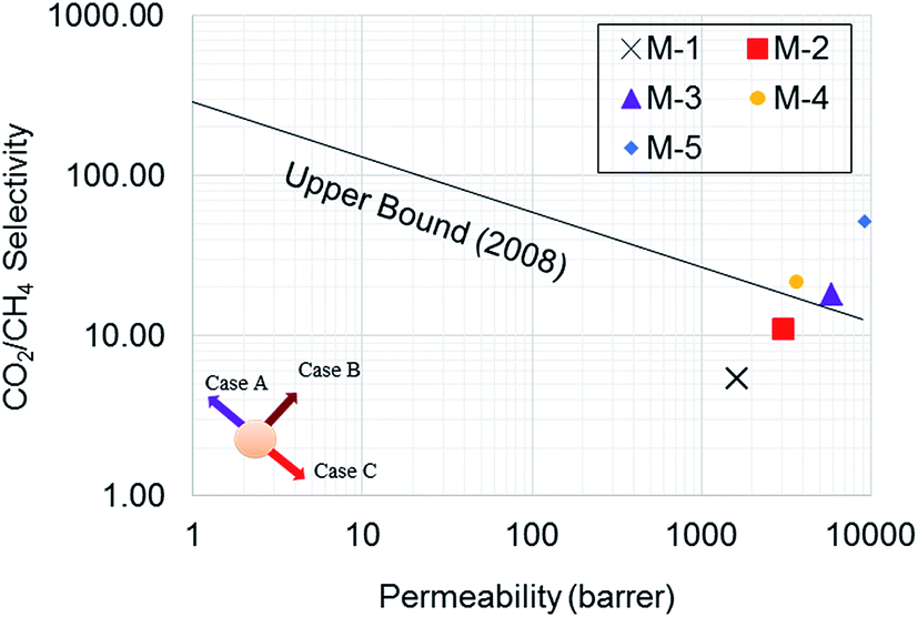 | ||
| Fig. 11 The performances of neat PES (M-1), PES–CMS (M-2), PES–CMS–DEA (5–15 wt%) (M-3–M-5) relative to the Robeson's upper bound line for CO2/CH4. | ||
3.6 Comparison of performance of MMMs
MMMs in which different fillers and third components were incorporated in PES have been reported during the past years. Most of PES/filler MMMs were prepared as dense membranes in earlier studies focusing on the changes in gas solubility and diffusivity with filler incorporation and CO2 permeability was reported. The developed membranes with the addition of CMS and DEA exhibited comparable better performance when compared with other mixed matrix membranes listed in Table 4.| Polymer | Filler | Third component | CO2 permeance | Ideal selectivity | Ref. |
|---|---|---|---|---|---|
| a Barrer.b GPU. | |||||
| PES | SAPO-34 | HMA | 3.58a | 29.8 | E. Karatay et al.17 |
| PES | SAPO-34 | Ionic liquid | 279.26b | 60.62 | D. F. Mohshim et al.20 |
| PC | Zeolite 4A | p-nitroaniline | 3.23a | 43.64 | D. Şen et al.59 |
| PES | MWCNT | — | 7.74b | 19.57 | A. Ismail et al.60 |
| PES | CMS | DEA | 106.65b | 51.39 | This work |
4 Conclusions
In this study, CMS and DEA were added in PES to develop the amine mixed matrix membrane with CO2 and CH4 permeation properties. FESEM analyses confirmed the dense and no porous structure. TGA analysis revealed that the thermal properties of developed amine MMMs improved by the addition of CMS and DEA. It was found that addition of CMS and DEA in PES matrix results in noticeable improvement of CO2 permeance and CO2/CH4 selectivity. The highest value of selectivity (51.39) was achieved by the 15 wt% addition of DEA at operating condition of 10 bar and 25 °C. Lastly, the combined effect of CMS and DEA in this study has proven as a straightforward approach to simultaneously increased in CO2 permeance and CO2/CH4 selectivity and shifted above the Robeson's upper bound line 2008, would valuable for future works focused on MMMs for gas separation, especially for CO2 removal.Acknowledgements
The authors acknowledge the financial support provided by Ministry of Science, Technology and Innovation (MOSTI) e-Science fund (0153AB-B57) and Universiti Teknologi PETRONAS.References
- A. Ebadi Amooghin, M. Omidkhah and A. Kargari, RSC Adv., 2015, 5, 8552–8565 RSC.
- R. W. Baker and K. Lokhandwala, Ind. Eng. Chem. Res., 2008, 47, 2109–2121 CrossRef CAS.
- M. Rezakazemi, A. Ebadi Amooghin, M. M. Montazer-Rahmati, A. F. Ismail and T. Matsuura, Prog. Polym. Sci., 2014, 39, 817–861 CrossRef CAS PubMed.
- N. A. H. Md Nordin, S. M. Racha, T. Matsuura, N. Misdan, N. A. A. Sani, A. F. Ismail and A. Mustafa, RSC Adv., 2015, 5, 43110–43120 RSC.
- D. D. a. M. S. Tom Cnop, Continued Development of Gas Separation Membranes for Highly Source Service, 2007.
- G. Bellussi, P. Broccia, A. Carati, R. Millini, P. Pollesel, C. Rizzo and M. Tagliabue, Microporous Mesoporous Mater., 2011, 146, 134–140 CrossRef CAS PubMed.
- A. K. Datta and P. K. Sen, J. Membr. Sci., 2006, 283, 291–300 CrossRef CAS PubMed.
- M. G. Buonomenna, RSC Adv., 2013, 3, 5694–5740 RSC.
- S. P. Nunes and K. V. Peinemann, Membrane technology, Wiley Online Library, 2001 Search PubMed.
- L. M. Robeson, J. Membr. Sci., 1991, 62, 165–185 CrossRef CAS.
- M. Salavati-Niasari, Polyhedron, 2009, 28, 2321–2328 CrossRef CAS PubMed.
- R. Szostak, Molecular Sieves: Principles of Synthesis and Identification, Blackie Academic and Professional, New York, 1998 Search PubMed.
- R. Nasir, H. Mukhtar, Z. Man and D. F. Mohshim, Chem. Eng. Technol., 2013, 36, 717–727 CrossRef CAS PubMed.
- T. T. Moore, R. Mahajan, D. Q. Vu and W. J. Koros, AIChE J., 2004, 50, 311–321 CrossRef CAS PubMed.
- D. F. Mohshim, H. b. Mukhtar, Z. Man and R. Nasir, J. Eng., 2013, 2013, 7 Search PubMed.
- G. Dong, H. Li and V. Chen, J. Mater. Chem. A, 2013, 1, 4610–4630 CAS.
- E. Karatay, H. Kalıpçılar and L. Yılmaz, J. Membr. Sci., 2010, 364, 75–81 CrossRef CAS PubMed.
- H. H. Yong, H. C. Park, Y. S. Kang, J. Won and W. N. Kim, J. Membr. Sci., 2001, 188, 151–163 CrossRef CAS.
- U. Cakal, L. Yilmaz and H. Kalipcilar, J. Membr. Sci., 2012, 417, 45–51 CrossRef PubMed.
- D. F. Mohshim, H. Mukhtar and Z. Man, Sep. Purif. Technol., 2014, 135, 252–258 CrossRef CAS PubMed.
- J. Chiou, Y. Maeda and D. Paul, J. Appl. Polym. Sci., 1987, 33, 1823–1828 CrossRef CAS PubMed.
- A. Singh and W. Koros, Ind. Eng. Chem. Res., 1996, 35, 1231–1234 CrossRef CAS.
- D. Q. Vu, W. J. Koros and S. J. Miller, Ind. Eng. Chem. Res., 2002, 41, 367–380 CrossRef CAS.
- G. J. Francisco, A. Chakma and X. Feng, J. Membr. Sci., 2007, 303, 54–63 CrossRef CAS PubMed.
- P. N. Sutar, A. Jha, P. D. Vaidya and E. Y. Kenig, Chem. Eng. J., 2012, 207, 718–724 CrossRef PubMed.
- A. L. Kohl and R. B. Nielsen, Gas purification, Gulf Professional Publishing, 1997 Search PubMed.
- M. Z. Pedram, M. Omidkhah, A. E. Amooghin and R. Yegani, Polym. Eng. Sci., 2014, 54, 1268–1279 CAS.
- M. Omidkhah, M. Pedram and A. Amooghin, J Membra Sci Technol, 2013, 3, 2 Search PubMed.
- J. Kärger and D. Ruthven, Diffusion in zeolites and other microporous solids, Wiley, New York, 1992 Search PubMed.
- Y. S. Bae and C. H. Lee, Carbon, 2005, 43, 95–107 CrossRef CAS PubMed.
- G. Watson, E. May, B. Graham, M. Trebble, R. Trengove and K. Chan, J. Chem. Eng. Data, 2009, 54, 2701–2707 CrossRef CAS.
- M. Farrokhnia, M. Rashidzadeh, A. Safekordi and G. Khanbabaei, Iran. Polym. J., 2015, 24, 171–183 CrossRef CAS.
- R. Nasir, H. Mukhtar, Z. Man, B. K. Dutta, M. S. Shaharun and M. Z. Abu Bakar, J. Membr. Sci., 2015, 483, 84–93 CrossRef CAS PubMed.
- S. Palaniandy, K. A. M. Azizli, H. Hussin and S. F. S. Hashim, Int. J. Miner. Process., 2007, 82, 195–202 CrossRef CAS PubMed.
- M. Myekhlai, B. Munkhbayar, T. Lee, M. R. Tanshen, H. Chung and H. Jeong, RSC Adv., 2014, 4, 2495–2500 RSC.
- T. Li, F. Sui, F. Li, Y. Cai and Z. Jin, Powder Technol., 2014, 254, 338–343 CrossRef CAS PubMed.
- K. Lenghaus, G. GuangHua Qiao, D. H. Solomon, C. Gomez, F. Rodriguez-Reinoso and A. Sepulveda-Escribano, Carbon, 2002, 40, 743–749 CrossRef CAS.
- R. Abedini, M. Omidkhah and F. Dorosti, RSC Adv., 2014, 4, 36522–36537 RSC.
- R. Nasir, H. Mukhtar, M. Shima Shaharun and Z. Man, Appl. Mech. Mater., 2015, 754, 869–873 CrossRef.
- J. Han, W. Lee, J. M. Choi, R. Patel and B.-R. Min, J. Membr. Sci., 2010, 351, 141–148 CrossRef CAS PubMed.
- M. Iqbal, Z. Man, H. Mukhtar and B. K. Dutta, J. Membr. Sci., 2008, 318, 167–175 CrossRef CAS PubMed.
- R. Guan, H. Dai, C. Li, J. Liu and J. Xu, J. Membr. Sci., 2006, 277, 148–156 CrossRef CAS PubMed.
- J. Yu, L. Li, N. Liu and R. Lee, J. Mater. Sci., 2013, 48, 3782–3788 CrossRef CAS.
- S. Rafiq, Z. Man, S. Maitra, N. Muhammad and F. Ahmad, J. Appl. Polym. Sci., 2012, 123, 3755–3763 CrossRef CAS PubMed.
- M. Z. Pedram, M. Omidkhah, A. E. Amooghin and R. Yegani, Polym. Eng. Sci., 2014, 54, 1268–1279 CAS.
- G. J. Francisco, A. Chakma and X. Feng, Sep. Purif. Technol., 2010, 71, 205–213 CrossRef CAS PubMed.
- M. Pixton, D. Paul and Y. Yampol'skii, Relationships between structure and transport properties for polymers with aromatic backbones, CRC Press, Boca Raton, FL, 1994 Search PubMed.
- A. Ismail and N. Yaacob, Journal of membrane science, 2006, 275, 151–165 CrossRef CAS PubMed.
- A. L. Khan, X. Li and I. F. Vankelecom, J. Membr. Sci., 2011, 380, 55–62 CrossRef CAS PubMed.
- D. Paul and W. Koros, J. Polym. Sci., Part B: Polym. Phys., 1976, 14, 675–685 CrossRef CAS PubMed.
- C. Ma and W. J. Koros, J. Membr. Sci., 2013, 428, 251–259 CrossRef CAS PubMed.
- S. Rafiq, Z. Man, A. Maulud, N. Muhammad and S. Maitra, J. Membr. Sci., 2011, 378, 444–452 CrossRef CAS PubMed.
- S. Saedi, S. S. Madaeni and A. A. Shamsabadi, Chem. Eng. Res. Des., 2014, 92, 2431–2438 CrossRef CAS PubMed.
- S. Basu, A. Cano-Odena and I. F. Vankelecom, Sep. Purif. Technol., 2010, 75, 15–21 CrossRef CAS PubMed.
- M. Peydayesh, S. Asarehpour, T. Mohammadi and O. Bakhtiari, Chem. Eng. Res. Des., 2013, 91, 1335–1342 CrossRef CAS PubMed.
- A. S. Wiryoatmojo, H. Mukhtar and Z. Man, Development of Polysulfone-Carbon Molecular Sieves Mixed Matrix Membranes for CO2 Removal From natural Gas, in Chemical, Biological and Environmental Engineering: Proceedings of the International Conference on Cbee 2009, 2009, p. 249 Search PubMed.
- L. M. Robeson, J. Membr. Sci., 2008, 320, 390–400 CrossRef CAS PubMed.
- T. T. Moore and W. J. Koros, J. Mol. Struct., 2005, 739, 87–98 CrossRef CAS PubMed.
- D. Şen, H. Kalıpçılar and L. Yilmaz, J. Membr. Sci., 2007, 303, 194–203 CrossRef PubMed.
- A. Ismail, N. Rahim, A. Mustafa, T. Matsuura, B. Ng, S. Abdullah and S. Hashemifard, Sep. Purif. Technol., 2011, 80, 20–31 CrossRef CAS PubMed.
| This journal is © The Royal Society of Chemistry 2015 |