Catalytic performance of Co/Zn–Al2O3 Fischer–Tropsch catalysts: a comparative study of zinc introduction methodologies

Juan Dua, Junkun Yana, Jingping Hong*a, Yuhua Zhanga, Sufang Chenb and Jinlin Lia
aKey Laboratory of Catalysis and Materials Science of the State Ethnic Affairs Commission & Ministry of Education, South-Central University for Nationalities, Wuhan, Hubei 430073, China. E-mail: jingpinghong@mail.scuec.edu.cn; Fax: +86 27 67842752; Tel: +86 27 67843016
bKey Laboratory for Green Chemical Process of Ministry of Education, School of Chemical Engineering and Pharmacy, Wuhan Institute of Technology, Wuhan, Hubei 430073, China

Received 13th May 2015 , Accepted 3rd July 2015

First published on 3rd July 2015


Abstract

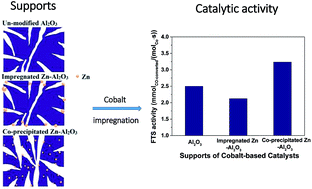
Zinc was introduced into γ-Al2O3 by either co-precipitation or impregnation methods. Zinc introduced by co-precipitation was homogeneously dispersed in the framework of the support, while it was aggregated on the surface of alumina upon addition via impregnation. The co-precipitated prepared Zn–Al2O3 supported cobalt catalyst possessed appropriate pore structure, lower cobalt–support interaction and improved cobalt reducibility, thus showing a significantly enhanced catalytic activity with good stability in Fischer–Tropsch synthesis.

1 Introduction

Fischer–Tropsch synthesis (FTS) is a potential alternative to petroleum for the production of ultraclean and sustainable automotive fuels. It uses syngas as feedstock, which can be derived from natural gas, coal, or renewable biomass resources.1–6

Cobalt-based catalysts are one of the most important candidates for FTS because of their acceptable cost, high activity, low water–gas shift activity and high selectivity to long chain paraffins.7,8 Cobalt precursors are usually dispersed on porous supports to obtain a high density of cobalt sites. Conventional supports such as titania,9 alumina,10 silica11 and zirconia12 exhibit varying degrees of cobalt–support interactions, which significantly influence the reducibility and dispersion of supported cobalt catalysts, and thereby, affect the final catalytic activity and products selectivity. A controllable catalyst design is able to fine-tune support–cobalt interactions, and will be highly desirable to improve the catalytic performance of FTS catalysts.

Alumina is a traditional commercial support due to its favourable mechanical and controllable surface properties.13 However, a strong interaction between alumina and cobalt oxides limits the reducibility of cobalt species.14 Modification of the support surface by certain amounts of noble metals,15–17 other metal oxides,18–20 or organic compounds,21,22 could modify the interaction between cobalt oxide and support, increase the cobalt reducibility and thus, improve catalyst performance.

Zinc is a commonly used promoter or support (ZnO) and has been studied in a wide range of reactions, including FTS.23–30 As an additive, zinc affects the structure and catalytic performance of corresponding catalysts.27–29,31 Coville et al.31–33 reported that zinc had a positive effect on the activity and the selectivity of Co/TiO2 catalysts, however, related studies34 showed that low content Zn (1–5 wt%) was acted as a poison and decreased the activity of Co/Al2O3 catalysts during CO hydrogenation at steady-state isotopic transient kinetic analysis conditions. The controversial results led us to perform the comparative study of zinc introduction methodologies (co-precipitation or impregnation) in this work; the effects of zinc modification on the catalyst structure and catalytic performance in FTS were investigated. Various characterization methods as well as FTS tests were employed to provide in-depth information about the catalysts structure and reactive performance.

2 Experimental

2.1 Catalyst preparation

Support preparation. The pure alumina support denoted as Al1 was prepared by co-precipitation method through the following procedure. A known amount of aluminum nitrate aqueous solution was stirred by a magnetic stirrer, then pure ammonia aqueous solution (25 wt%) was added drop-wise until the pH value of the solution reached 9. After stirring for another 2 h, the generated precipitate was filtered and washed thoroughly by distilled water and anhydrous ethanol. The obtained precipitate was dried at 383 K for 12 h, and calcined at 973 K for 5 h.

Zinc was introduced into alumina by two methods. One was introduced by co-precipitation method and labelled as PZnAl1. The support was synthesized following the same procedures as Al1, the only difference was during the first step, mixed aluminum nitrate and zinc nitrate aqueous solution was used instead of pure aluminum nitrate aqueous solution. The other was introduced by traditional incipient wetness impregnation. Zinc nitrate was impregnated on Al1 material, followed by drying at 383 K for 12 h, and calcining at 973 K for 5 h. The obtained support was marked as IZnAl1. The theoretic zinc loading in both final samples is 10 wt%. Inductively coupled plasma mass spectrometry (ICP-MS) analysis confirmed that the content of Zn cations in PZnAl1 and IZnAl1 was approximately equal to the nominal value.

To eliminate the effect of support pore structure, another alumina support (Al2) with similar specific surface area and pore size distribution as PZnAl1, was also synthesized by co-precipitation method, following the same preparation process of Al1, but using hexadecyl trimethyl ammonium bromide (CTAB) instead of ammonia as precipitator.

Cobalt deposition. Cobalt was deposited on the supports by incipient wetness impregnation using solutions containing the desired amount of cobalt nitrate. The samples were dried at 393 K for 12 h, and then calcined at 623 K in air for 5 h, with a ramping rate of 2 K min−1. The catalysts were labelled as Co/Al1, Co/PZnAl1, Co/IZnAl1 and Co/Al2, respectively. The nominal loading of cobalt in these four catalysts was 15 wt%.

2.2 Catalyst characterization

The BET surface area, pore volume and pore size distribution were obtained from nitrogen adsorption and desorption isotherms, performed at 77 K, using a constant-volume adsorption apparatus (Quantachrome Autosorb-1-C-MS). The pore volume was determined at a relative pressure (P/P0) of 0.99. The pore size distributions of the samples were determined by the BJH (Barett–Joyner–Halenda) model from the data of desorption branch of the nitrogen isotherms.

X-ray diffraction (XRD) spectra were recorded on a Bruker Advanced D8 powder X-ray diffractometer, with monochromatic CuKα radiation and a VANTEC-1 detector over a 2θ range of 10–80°, with a step size of 0.0167°. Crystallite phases were determined by comparing the diffraction patterns with those in the standard powder XRD files (JCPDS). In situ XRD measurements were carried out under a pure hydrogen gas flow, from 423 K to 723 K with a heating rate of 1 K min−1, followed by several scans taken in an interval of 1 h. The average Co3O4 crystallite size was calculated by line broadening analysis of Co3O4 peak using the Scherrer equation.

27Al solid-state magnetic angle spinning nuclear magnetic resonance (27Al MAS NMR) spectra were recorded at room temperature on a Bruker MSL-400 spectrometer, with zirconia rotors spun at 5 kHz, using a commercial 4 mm MAS NMR probe. Data were acquired at 104.26 MHz, 14.5 μs pulse width and 1 s recycle delay, using Al(NO3)3·9H2O as the reference. The chemical shifts were given in ppm.

H2-temperature-programmed reduction (H2-TPR) measurements were performed on a Zeton Altamira AMI-200 unit. The calcined catalysts placed in a U-shape quartz reactor, after removing the adsorbed water and other contaminants, a 10% H2/Ar (constant flow rate of 30 ml min−1) flow was introduced into the reactor and the temperature was raised to 1073 K, with a ramping rate of 10 K min−1. The consumption of H2 was monitored by a thermal conductivity detector.

The dispersion and crystallite size of cobalt were measured by hydrogen temperature programmed desorption and oxygen titration, using the Zeton Altamira AMI-200 unit. The catalysts were firstly reduced at 723 K, for 12 h in a hydrogen flow. Then the catalysts were purged with argon at 373 K to drive away weakly bound physisorbed species. After that, the temperature increased from 373 K to 723 K with a heating rate of 10 K min−1 and held at 723 K, under flowing argon, to desorb the remaining chemisorbed hydrogen. Meanwhile, the TCD signal was recorded until it returned to the baseline. Subsequently, the reduced catalyst was re-oxidized at 723 K, by purging with oxygen pulses until no further consumption of O2 was detected by the TCD located downstream. The detailed description of how to calculate the cobalt catalyst dispersion and reduction degree has been reported previously.14

Raman spectra were performed on a Confocal Renishaw RM-1000 instrument with Ar ion laser of wavelength 514.5 nm. The laser power was adjusted at 7 mW with an exposure of 30 s after 3 accumulations.

2.3 Fischer–Tropsch synthesis tests

The FTS reaction were carried out in a fixed-bed stainless-steel reactor (id = 12 mm). Typically, 0.5 g catalyst was mixed with 5 g same-sized inert silicon carbide particles to improve the temperature distribution. After reduction in flowing H2 at 723 K, for 10 h under atmospheric pressure, the temperature of catalyst bed was cooled down to 373 K in flowing H2. The system pressure was then increased to 1.0 MPa by a syngas flow with a H2[thin space (1/6-em)]:[thin space (1/6-em)]CO ratio of 2[thin space (1/6-em)]:[thin space (1/6-em)]1. The gas flow was set at a space velocity of 4 SL g−1 h−1 and the reaction temperature was slowly increased to 493 K. The reaction products were collected after more than 80 h of operation, to achieve a good mass balance at close to steady state. Liquid products and wax were collected through a cold trap keeping at 273 K and a hot trap keeping at 393 K, respectively. Gaseous products were analyzed on line by an Agilent MicroGC 3000A gas chromatograph (GC). The oil and wax fractions were analyzed by flame ionization detector (FID) with an Agilent GC7890 and Agilent GC6890, respectively. The mass balance and carbon balance of the reaction were both in the range of 94% to 103%. Detailed information can be found in our previous report.35

3 Results and discussion

3.1 Structure of supports and corresponding catalysts

The nitrogen adsorption–desorption isotherms for the supports and corresponding catalysts are shown in Fig. 1, and their surface area, pore diameter and pore volume data are listed in Table 1. All the supports and catalysts presented representative type-IV isotherms with pronounced H2 hysteresis loops according to the classification of Brunauer et al.,36 which was typical of mesoporous materials. The pore diameter of the supports and corresponding catalysts were calculated using the BJH method. The porosity of the supports was significantly affected by the introduction methods of zinc. The PZnAl1 support, in which Zn was introduced by co-precipitation method, showed the highest BET surface area, highest pore volume and widest average pore size, while IZnAl1 support (Zn introduced by impregnation method) presented opposite values (Table 1). It is thus suggested that in PZnAl1, Zn entered into the framework of alumina and altered its structure, whereas in IZnAl1 support, zinc was mainly existed on the surface of the matrix γ-Al2O3, causing some blocking of the pores in Al1. The Al2 support, which had similar pore structure as PZnAl1, was used as a reference to compare and better understand the effect of support structure.
image file: c5ra08965d-f1.tif
Fig. 1 Nitrogen adsorption–desorption isotherms of supports (a) and catalysts (b).
Table 1 Textural parameters of supports and catalysts
Support SBET (m2 g−1) BJH pore size (nm) Pore volume (cm3 g−1) Catalyst SBET (m2 g−1) BJH pore size (nm) Pore volume (cm3 g−1)
Al1 182.0 7.2 0.59 Co/Al1 132.9 5.9 0.42
IZnAl1 136.3 6.1 0.49 Co/IZnAl1 106.7 5.1 0.34
PZnAl1 234.1 12.5 0.86 Co/PZnAl1 189.5 10.6 0.63
Al2 222.8 11.4 0.78 Co/Al2 180.6 9.8 0.54


Similar pore size distribution curves and nitrogen adsorption–desorption isotherms in the supported catalysts (Fig. 2) suggested that impregnation of cobalt had no effect on the structure of the corresponding supports. The drop of surface area could be due both to plugging support pores with cobalt oxide crystallites and to the effect of the support “dilution” because of the presence of cobalt species.37


image file: c5ra08965d-f2.tif
Fig. 2 Pore size distribution of supports (a) and catalysts (b).

The properties of aluminum in the supports were investigated by 27Al MAS NMR spectroscopy. The 27Al chemical shifts were easily distinguished among different coordination numbers for aluminum species.38 The 27Al MAS NMR spectra of PZnAl1, IZnAl1 and Al1 supports are shown in Fig. 3. For all three samples, there are two main resonance peaks observed around δ = 0 ppm and 68 ppm, which corresponded to aluminum species in octahedral (Alocta) coordination and tetrahedral (Altetra) coordination, respectively.39 It was demonstrated that the modification of zinc on Al2O3 by both co-precipitation and impregnation, led to an increase in the concentration of Al in octahedral coordination. Since Al species in pure ZnAl2O4 are mostly in the form of octahedral coordination,40 the increased ratio of Alocta to Altetra in the supports after zinc modification suggested the formation of ZnAl2O4 species, and the higher Alocta/Altetra ratio in PZnAl1 indicated a higher concentration of ZnAl2O4 species.


image file: c5ra08965d-f3.tif
Fig. 3 27Al solid-state MAS NMR spectra of Al1, PZnAl1 and IZnAl1, the peak area ratios of Alocta to Altetra were labelled.

The supports and corresponding catalysts were also characterized by X-ray diffraction. Wide-angle XRD patterns of the Al1, Al2, PZnAl1 and IZnAl1 supports are presented in Fig. 4. Diffraction peaks located at 37.6°, 39.5°, 45.7° and 67.0° were attributed to the γ-Al2O3 phase (JCPDS: 47-1308), while the peaks at 31.2°, 36.8°, 44.8°, 55.6°, 59.3° and 65.2° in the PZnAl1 and IZnAl1 samples were assigned to the ZnAl2O4 phase, with spinel structure (JCPDS: 05-0669). No characteristic diffraction peak of ZnO was detected under experimental conditions. Therefore, we draw the inference that zinc, doped by either co-precipitation or impregnation, could react with a matrix of γ-Al2O3 and form zinc aluminate with spinel structure after high temperature calcination, the result is consistent with the investigation made by Strohmeier et al.,41 the strong interaction between zinc and γ-Al2O3 led to the formation of ZnAl2O4 when the zinc loading was not exceeded 20%. The diffraction peaks of Al2O3 are completely overlapped with those of ZnAl2O4 in PZnAl1, indicating the homogeneous dispersion of ZnAl2O4 in the framework of γ-Al2O3. Comparing with PZnAl1, the diffraction peak of γ-Al2O3 at 39.5° could be clearly distinguished in IZnAl1, and the shape of various overlapped peaks was narrower and sharper, suggesting the formation of larger ZnAl2O4 crystallites on the surface of γ-Al2O3 matrix when zinc was introduced by impregnation method. These larger particles blocked the pore channels in original Al1 material, and led to a decrease in surface area, pore volume and average pore size, consistent with nitrogen physisorption data.


image file: c5ra08965d-f4.tif
Fig. 4 Powder XRD patterns of the supports.

X-ray diffraction profiles of the catalysts are shown in Fig. 5. XRD patterns characteristic of Co3O4 were detected for Al2O3 supported catalysts. However, the diffraction peaks of Al2O3, ZnAl2O4 and Co3O4 phases are all overlapped to a large extent in zinc containing samples. Thus, it is difficult to calculate the crystallite size of Co3O4 in Co/IZnAl1 and Co/PZnAl1 catalysts by Scherrer equation. After subtracting the contribution of the supports, the Co3O4 particle size of pure alumina supported Co/Al1 and Co/Al2 catalysts is assessed from the width of (511) diffraction peaks (Table 2), the Co/Al2 catalyst, with larger pores in support, has larger Co3O4 particles.


image file: c5ra08965d-f5.tif
Fig. 5 X-Ray diffraction patterns of calcined catalysts.
Table 2 Particle size of cobalt species at different conditions
Catalyst DCo3O4a (nm) DCo-FCb (nm) DCo-FCc (nm) DCo-UCd (nm) RDe (%)
a Average particle size of Co3O4 determined by XRD using Scherrer equation.b Cobalt particle size of fresh catalyst, determined by in situ XRD at 2θ = 44.8°.c Cobalt particle size of fresh catalyst, determined by H2-TPD and O2 titration.d Cobalt particle size of used catalyst, determined by H2-TPD and O2 titration.e Reduction degree, data obtained from O2 titration.
Co/Al1 9.8 8.0 6.0 6.6 42.1
Co/IZnAl1 7.9 5.4 8.2 36.3
Co/PZnAl1 9.8 7.2 7.6 61.7
Co/Al2 11.8 9.3 6.6 7.2 53.6


In order to obtain the cobalt particle size data in zinc containing catalysts, H2-temperature programmed desorption (H2-TPD) and O2-titration experiments were carried out and the derived data are shown in Table 2. With the same variation tendency as XRD findings, it confirmed that the particle size of the cobalt species was related to the support pore size. The particle size of Co3O4 in Co/PZnAl1 and Co/Al2 catalysts was corresponding to the pore size of their counterpart supports. While in Co/Al1 and Co/IZnAl1 samples, although smaller Co3O4 crystallites were found, they were still much larger than the pore size of supports, indicating that a fraction of cobalt oxide might not be situated inside the pores but on the outer surface.18

The influence of zinc addition with different methods on the cobalt reducibility of supported catalysts was firstly investigated by temperature programmed reduction (TPR). Several hydrogen consumption peaks are observed in the TPR profiles of the four catalysts (Fig. 6). Peaks below 550 K could be attributed to the reductive decomposition of residual nitrate species.16,42 And the peaks between 550 K and 673 K were assigned to the reduction of Co3O4 to CoO (ref. 43) for all catalysts. The intensity and position of this peak were not markedly changed by zinc modification or difference in support structure, indicating that the first reduction step of supported Co3O4 to CoO, did not significantly depend on catalyst properties. Similar conclusion was also illustrated by Castner et al.44 The second reduction step (reduction of CoO into Co0) of four catalysts was taken place at a relative wide temperature range (673–1000 K),45 corresponding to the progressive reduction of CoO–alumina species with different interaction strength, or of cobalt aluminate, which might be formed by a reaction between smaller CoO particles and alumina at elevated temperatures in the presence of water-vapor, producing during the reduction process.46 In contrast with the first step reduction, the reduction of CoO to Co0 was largely dependent upon the nature of the catalyst. It is known that smaller cobalt oxide particles usually have stronger interaction with supports, and they are more difficult to reduce than larger cobalt oxide particles. Hence, the Co/Al1 and Co/IZnAl1 catalysts with smaller Co3O4 crystallites have relative high final reduction temperatures. The highest reducibility of cobalt species in Co/PZnAl1 catalyst was due to a combined effect of larger Co3O4 particles, as well as a weakened cobalt–support interaction.


image file: c5ra08965d-f6.tif
Fig. 6 TPR spectra of calcined catalysts.

To better understand the reduction stages of these catalysts, in situ XRD measurements in pure hydrogen atmosphere during heat treatment were also employed in this study. As shown in Fig. 7, all the four catalysts showed two reduction steps and the Co3O4 phase transformed into CoO when the temperature reached 573 K, confirming TPR results that the reduction of Co3O4 to CoO was regardless of the support composition and structure. Nevertheless, the appearance temperature of metallic Co diffraction peaks in the catalysts varied. Metallic cobalt diffraction could be found as soon as the temperature reached 753 K in Co/PZnAl1, while in Co/Al1, Co/IZnAl1 and Co/Al2, the temperatures were 833 K, 833 K and 793 K, respectively. The appearance temperatures of metallic Co metal were in the following order: Co/PZnAl1 < Co/Al2 < Co/IZnAl1 ≈ Co/Al1. Compared with the reduction process of two catalysts (Co/PZnAl1 and Co/Al2) with similar cobalt particle size, the improved reducibility in Co/PZnAl1 suggested that the existence of co-precipitated Zn in support could weaken the interaction between the support and cobalt, hinder the formation of cobalt aluminates by the reaction of CoO and alumina at elevated temperature, and thus, enhance the reduction stage of CoO to Co0.


image file: c5ra08965d-f7.tif
Fig. 7 In situ XRD patterns of (a) Co/Al1, (b) Co/IZnAl1, (c) Co/PZnAl1 and (d) Co/Al2.

The reducibility of the four catalysts was also measured by H2-temperature programmed desorption (H2-TPD) and O2-titration experiments, the results are shown in Table 2. Eliminating the influence of support pore size (compared both with Co/Al1 and Co/Al2), Co/PZnAl1 catalyst showed the highest final cobalt reducibility, in consistent with the above TPR and in situ XRD findings. The reducibility of cobalt catalysts was affected by both the cobalt particle size47 and metal–support interaction.48 The relative low reduction degree of Co/IZnAl1 could be ascribed both to its smallest Co3O4 particles which are much more difficult to reduce, and the aggregation of ZnAl2O4 spines, which showed lower impact on the weakening of cobalt–alumina interaction.

3.2 Catalytic performance

The catalytic performance of cobalt-based catalysts was evaluated in a differential catalytic reactor at 493 K, under 1.0 MPa. Since all of the catalysts had the same cobalt loading and are performed under same reaction conditions, their catalytic activity expressed as FTS reaction rate (in moles of converted CO per second divided by the total amount of cobalt (in moles) loaded into the reactor), were in direct proportion to CO conversion, as shown in Fig. 8 and Table 3. The activity of the catalysts at quasi-steady state was in the order of Co/IZnAl1 < Co/Al1 < Co/Al2< Co/PZnAl1, while the selectivities of hydrocarbons were not remarkably changed.
image file: c5ra08965d-f8.tif
Fig. 8 CO conversion of the four catalysts as a function of time on stream.
Table 3 FTS performances of cobalt catalysts in a fixed bed reactora
Catalyst XCOb (%) FTS reaction rate (10−3 s−1) Hydrocarbon selectivity (mol%) Carbon balance
SC1 SC2–4 SC5+
a Reaction conditions: 1.0 MPa, 493 K, H2/CO = 2, 4 SL g−1 h−1, CO conversion and hydrocarbon selectivity were collected at 100 h.b Average CO conversion, recorded at quasi-steady state.
Co/Al1 38.5 2.5 12.2 10.2 77.6 99.1%
Co/IZnAl1 32.7 2.2 13.8 9.3 76.9 95.3%
Co/PZnAl1 49.8 3.3 12.3 10.0 77.7 101.8%
Co/Al2 43.3 2.9 11.9 8.8 79.3 98.3%


It is generally accepted that when the cobalt particle size is larger than 6–8 nm, the activity of cobalt catalysts for FTS is dependent upon the amount of the exposed active metal cobalt sites, which are decided by both cobalt dispersion and reducibility. We show here that in Co/PZnAl1, zinc is entered into the framework of alumina by co-precipitation method and forms homogeneous dispersed zinc aluminate after calcination. The obtained Al2O3–ZnAl2O4 material (PZnAl1) confined the cobalt particles inside its pores, and weakened the interaction between the cobalt and support, thus, the reducibility of corresponding catalyst was improved and an enhancement in FTS activity was achieved.

It is known that the catalytic deactivation in FTS could be due to sintering of cobalt nanoparticles, cobalt oxidation, carbon (wax) deposition, etc. Compared with the other three catalysts, more significant deactivation was presented on Co/IZnAl1 (from initially 41.0% to 32.7%, declined by 20.2%). The particle sizes of cobalt species in fresh reduced catalysts and corresponding used ones are listed in Table 2, a much more remarkable sintering of cobalt particles (from 5.4 nm of the fresh catalyst to 8.2 nm of the used one, augmented by 51.9%) was observed on Co/IZnAl1, while for the other three catalysts, the augmentation of cobalt particle size after reaction was less than 10%.

In order to better analysis the deactivation mechanism of Co/IZnAl1 catalyst, Raman spectra of used Co/IZnAl1 and Co/PZnAl1 catalysts were recorded. As shown in Fig. 9, only bands arose from C–H stretching mode in the range of 2850–3100 cm−1 were detected, which suggested the presence of hydrocarbons on the catalysts. The huge and broad bands on Co/IZnAl1 catalyst indicated that besides cobalt sintering, wax deposition was also one of the possible factor in charge of the deactivation phenomena on this catalyst.


image file: c5ra08965d-f9.tif
Fig. 9 Raman spectra of used Co-based catalysts.

4 Conclusions

The addition of zinc by either co-precipitation or incipient wetness impregnation had strong impacts on support porosity, on the size of cobalt species, on the cobalt–support interaction and then, on cobalt reducibility, and finally on FTS catalytic activity. The deactivation of the catalysts during FTS was mainly due to the sintering of cobalt particles and wax deposition. Zinc introduced by co-precipitation could weaken the cobalt–alumina interaction and improve the reduction of CoO to Co0 in the corresponding Co/PZnAl1 catalyst, therefore, the Co/PZnAl1 catalyst, which combined high reducibility as well as comparable dispersion of cobalt species, showed the highest FTS activity and good reaction stability.

Acknowledgements

This work was supported by National Natural Science foundation of China (21203255, 21403158, 21473259), the Key Program of Technology Innovation of Hubei Province (2013AGB002), Technology Foundation for Selected Overseas Chinese Scholar, Ministry of Personnel of China (BZY14037) and the Fund for Basic Scientific Research of South-Central University for Nationalities (YZZ12001).

References

  1. H. Jahangiri, J. Bennett, P. Mahjoubi, K. Wilson and S. Gu, Catal. Sci. Technol., 2014, 4, 2210 CAS.
  2. A. Y. Khodakov, W. Chu and P. Fongarland, Chem. Rev., 2007, 107, 1692 CrossRef CAS PubMed.
  3. O. O. James, B. Chowdhury, M. A. Mesubi and S. Maity, RSC Adv., 2012, 2, 7347 RSC.
  4. Q. Zhang, W. Deng and Y. Wang, J. Energy Chem., 2013, 22, 27 CrossRef CAS.
  5. E. Iglesia, Appl. Catal., A, 1997, 161, 59 CrossRef CAS.
  6. J. M. Cho, C. I. Ahn, C. Pang and J. W. Bae, Catal. Sci. Technol., 2015, 5, 3525 CAS.
  7. B. H. Davis, Top. Catal., 2005, 32, 143 CrossRef CAS.
  8. Y. Liu, I. Florea, O. Ersen, C. Pham-Huu and C. Meny, Catal. Commun., 2015, 51, 145 CAS.
  9. K. Shimura, T. Miyazawa, T. Hanaoka and S. Hirata, Appl. Catal., A, 2013, 460–461, 8 CrossRef CAS PubMed.
  10. C. Ma, N. Yao, Q. Han and X. Li, Chem. Eng. J., 2012, 191, 534 CrossRef CAS PubMed.
  11. A. Y. Khodakov, A. Griboval-Constant, R. Bechara and V. L. Zholobenko, J. Catal., 2002, 206, 230 CrossRef CAS.
  12. W. Ma, G. Jacobs, P. Gao, T. Jermwongratanachai, W. D. Shafer, V. R. R. Pendyala, C. H. Yen, J. L. S. Klettlinger and B. H. Davis, Appl. Catal., A, 2014, 475, 314 CrossRef CAS PubMed.
  13. D. Wei, J. G. Goodwin Jr, R. Oukaci and A. H. Singleton, Appl. Catal., A, 2001, 210, 137 CrossRef CAS.
  14. G. Jacobs, T. K. Das, Y. Zhang, J. Li, G. Racoillet and B. H. Davis, Appl. Catal., A, 2002, 233, 263 CrossRef CAS.
  15. J. Hong, P. A. Chernavskii, A. Y. Khodakov and W. Chu, Catal. Today, 2009, 140, 135 CrossRef CAS PubMed.
  16. S. Vada, A. Hoff, E. ÅdnaneS, D. Schanke and A. Holmen, Top. Catal., 1995, 2, 155 CrossRef CAS.
  17. N. Osakoo, R. Henkei, S. Loiha, F. Roessner and J. Wittayakun, Appl. Catal., A, 2013, 464–465, 269 CrossRef CAS PubMed.
  18. J. Hong, W. Chu, P. A. Chernavskii and A. Y. Khodakov, Appl. Catal., A, 2010, 382, 28 CrossRef CAS PubMed.
  19. Y. Zhang, H. Xiong, K. Liew and J. Li, J. Mol. Catal. A: Chem., 2005, 237, 172 CrossRef CAS PubMed.
  20. S. Vada, B. Chen and J. G. Goodwin, J. Catal., 1995, 153, 224 CrossRef CAS.
  21. J. S. Girardon, E. Quinet, A. Griboval-Constant, P. A. Chernavskii, L. Gengembre and A. Y. Khodakov, J. Catal., 2007, 248, 143 CrossRef CAS PubMed.
  22. J. Hong, E. Marceau, A. Y. Khodakov, A. Griboval-Constant, C. La Fontaine, F. Villain, V. Briois and P. A. Chernavskii, Catal. Today, 2011, 175, 528 CrossRef CAS PubMed.
  23. K. Bharathi Yazhini and H. Gurumallesh Prabu, RSC Adv., 2015, 5, 49062 RSC.
  24. K. B. Gawande, S. B. Gawande, S. R. Thakare, V. R. Mate, S. R. Kadam, B. B. Kale and M. V. Kulkarni, RSC Adv., 2015, 5, 40429 RSC.
  25. R. P. Marin, S. A. Kondrat, T. E. Davies, D. J. Morgan, D. I. Enache, G. B. Combes, S. H. Taylor, J. K. Bartley and G. J. Hutchings, Catal. Sci. Technol., 2014, 4, 1970 CAS.
  26. N. N. Madikizela-Mnqanqeni and N. J. Coville, Appl. Catal., A, 2008, 340, 7 CrossRef CAS PubMed.
  27. J. Silvestre-Albero, A. Sepúlveda-Escribano, F. Rodríguez-Reinoso and J. A. Anderson, J. Catal., 2004, 223, 179 CrossRef CAS PubMed.
  28. Y. Zhang, Y. Zhou, J. Shi, X. Sheng, Y. Duan, S. Zhou and Z. Zhang, Fuel Process. Technol., 2012, 96, 220 CrossRef CAS PubMed.
  29. H. L. Janardhan, G. V. Shanbhag and A. B. Halgeri, Appl. Catal., A, 2014, 471, 12 CrossRef CAS PubMed.
  30. C. S. Spanjers, J. T. Held, M. J. Jones, D. D. Stanley, R. S. Sim, M. J. Janik and R. M. Rioux, J. Catal., 2014, 316, 164 CrossRef CAS PubMed.
  31. N. N. Madikizela-Mnqanqeni and N. J. Coville, Appl. Catal., A, 2007, 317, 195 CrossRef CAS PubMed.
  32. N. N. Madikizela and N. J. Coville, J. Mol. Catal. A: Chem., 2002, 181, 129 CrossRef CAS.
  33. N. N. Madikizela-Mnqanqeni and N. J. Coville, Appl. Catal., A, 2004, 272, 339 CrossRef CAS PubMed.
  34. B. C. Enger, V. Frøseth, J. Yang, E. Rytter and A. Holmen, J. Catal., 2013, 297, 187 CrossRef CAS PubMed.
  35. H. Xiong, Y. Zhang, S. Wang and J. Li, Catal. Commun., 2005, 6, 512 CrossRef CAS PubMed.
  36. S. Brunauer, L. S. Beming, W. S. Deming and E. Teller, J. Am. Chem. Soc., 1940, 62, 1732 CrossRef CAS.
  37. A. Y. Khodakov, A. Griboval-Constant, R. Bechara and V. L. Zholobenko, J. Catal., 2002, 206, 230 CrossRef CAS.
  38. N. J. van der Laag, M. D. Snel, P. C. M. M. Magusin and G. de With, J. Eur. Ceram. Soc., 2004, 24, 2417 CrossRef CAS PubMed.
  39. T. Mimani, J. Alloys Compd., 2001, 315, 123 CrossRef CAS.
  40. X. Duan, D. Yuan and F. Yu, Inorg. Chem., 2011, 50, 5460 CrossRef CAS PubMed.
  41. B. R. Strohmeier and D. M. Hercules, J. Catal., 1984, 86, 266 CrossRef CAS.
  42. Ø. Borg, E. Blekkan, S. Eri, D. Akporiaye, B. Vigerust, E. Rytter and A. Holmen, Top. Catal., 2007, 45, 39 CrossRef.
  43. B. Ernst, A. Bensaddik, L. Hilaire, P. Chaumette and A. Kiennemann, Catal. Today, 1998, 39, 329 CrossRef CAS.
  44. D. G. Castner, P. R. Watson and I. Y. Chan, J. Phys. Chem., 1990, 94, 819 CrossRef CAS.
  45. Ø. Borg, S. Eri, E. A. Blekkan, S. Storsæter, H. Wigum, E. Rytter and A. Holmen, J. Catal., 2007, 248, 89 CrossRef PubMed.
  46. I. Puskas, T. H. Fleisch, P. R. Full, J. A. Kaduk, C. L. Marshall and B. L. Meyers, Appl. Catal., A, 2006, 311, 146 CrossRef CAS PubMed.
  47. G. Prieto, A. Martínez, P. Concepción and R. Moreno-Tost, J. Catal., 2009, 266, 129 CrossRef CAS PubMed.
  48. S. Storsæter, B. Tøtdal, J. C. Walmsley, B. S. Tanem and A. Holmen, J. Catal., 2005, 236, 139 CrossRef PubMed.

This journal is © The Royal Society of Chemistry 2015
Click here to see how this site uses Cookies. View our privacy policy here.