Advances and challenges of sodium ion batteries as post lithium ion batteries
Monica Sawicki
and
Leon L. Shaw
*
Department of Mechanical, Materials and Aerospace Engineering, Wanger Institute for Sustainable Energy Research, Illinois Institute of Technology, 10 West 32nd Street, Chicago, IL 60616, USA. E-mail: lshaw2@iit.edu
First published on 10th June 2015
Abstract
Energy and climate concerns have made the need for research towards electrical energy storage. In this context, sodium ion batteries (SIBs) have attracted significant attention lately. Sodium is an abundant resource that is low cost and safe which makes it an attractive alternative to lithium. Its chemical properties are similar to that of Li which makes the transition into using Na chemistry for ion battery systems feasible. This review focuses on the latest progress in both cathode and anode materials for SIBs. It also details research in binders and additives and their effects on the SIB system. It further highlights the optimization of organic electrolytes and ionic liquid based electrolytes for utilization in SIBs. The mechanisms of sodium ion storage, transport, and solid electrolyte interphase formation are also discussed to better understand the behavior of ions and battery materials during de/intercalation. Finally, personal perspectives on outlook and major challenges ahead for SIBs are offered. These comprehensive and in-depth discussions along with proposed directions can enlighten ideas and offer avenues in the rational design of durable and high performance SIBs in the near future.
1. Introduction
Inevitable fossil fuel depletion has made the need for electrical energy storage systems (EES) extremely important. An efficient EES is crucial in order to stabilize the electrical energy grid by supplying a continuous flow of energy during off peak hours of intermittent renewable energy sources (e.g., wind, solar, and wave). The Department of Energy's goal for the cost of energy application on the electric grid to achieve 20% wind penetration is $100 kW h−1 by 2030.1 In addition, fossil fuel consumption of internal combustion engines gives rise to environmental pollution and the urgent need for high energy and high power density batteries for hybrid electric vehicles (HEVs), plug-in hybrid electric vehicles (PHEVs) and all electric vehicles (EVs). The battery specification for a 300 mile mid-range electric sedan is an energy density of 250 W h kg−1 at a cost $125 kW h−1.1–4 These emerging demands for electrical energy storage can lead to the overall depletion in lithium reserves.2,5,6The aforementioned specifications and eventual depletion of lithium have made sodium ion batteries (SIBs) an attractive alternative to lithium ion batteries (LIBs). The advent of the commercialized LIB by Sony in 1991 has made the use of portable electronics a part of everyday life. However, with increased demand for lithium metal arises the concern of the lithium supply because of its low abundance in the earth's crust, as shown in Fig. 1.4,6–8 Lithium resources are limited to North and South America, China, Australia, Portugal, and Zimbabwe; increased cost of mining and reliance of foreign import make it a necessity to explore alternative battery chemistries. SIBs have gained increased interest since sodium behaves similarly to lithium, is highly abundant, and low in cost as shown in Table 1.2,4,6 Furthermore, Na-based anodes allow the use of aluminum as a current collector which doesn't form a binary alloy with sodium, leading to further reduced cost (Table 1).
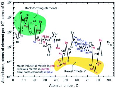 | ||
| Fig. 1 Abundance of elements in the earth's crust.4,7,8 | ||
| Sodium | Lithium | Category |
|---|---|---|
| 1.06 | 0.76 | Cation radius, Å |
| 23 g mol−1 | 6.9 g mol−1 | Atomic weight |
| −2.7 V | −3.04 V | E° (vs. SHE) |
| 97.7 °C | 180.5 °C | Melting point |
| $150 per ton | $5000 per ton | Cost, carbonates |
| At $2000–2500 per ton | Cu $7000–8500 per ton | Cost, current collectors at the anode |
| 1165 | 3829 | Capacity (mA h g−1), metal |
| Octahedral and prismatic | Octahedral and tetrahedral | A–O coordination preference |
Although SIBs are a promising alternative, they typically have poor electrochemical activity when compared to LIBs. This is due to two intrinsic shortcomings associated with Na. First, Na has a lower ionization potential than Li, leading to lower operating voltages and thus lower energy densities in comparison to LIBs. Second, Na+ ions are heavier and larger than Li+ ions, leading to slow diffusion within a solid electrode during cycling of SIBs and often larger volume expansion of the electrode when compared with LIBs.2–4,6 These intrinsic deficiencies give rise to the need for unique crystalline structures with an open framework structure or 3D structures with large insertion channels to facilitate the intercalation/de-intercalation process of the larger sodium ions.2,3,6,7,9 In spite of potentially lower gravimetric energy densities than LIBs, SIBs would be an optimal choice for use in EES for renewable sources. The requirements for large scale, stationary storage systems are ultra-long cycle life, high round trip efficiency, low cost, and high safety.2,4,7
Because of the unique advantages of SIBs over LIBs in the cost and nearly unlimited resources, the interest in SIBs has increased drastically over the last several years. This is reflected in rapid increases in the number of publications on SIBs. Note that there are eight review articles published in 2012–2014 alone.2–4,6,7,9–11 These reviews have focused on either electrode materials only7,9,11 or electrode materials plus electrolytes.2–4,9,10 However, the advancements and challenges in binders, additives and solid electrolyte interface (SEI) layer formation have not been addressed yet. In this review, we will update advancements made in cathodes, anodes and electrolytes while providing critical reviews of the progress made and challenges encountered in binders, additives and SEI layer formation. Furthermore, we will address the scientific understanding of the Na ion transport issue because the analysis of Na ion transport is essential in understanding the overall behavior of SIBs. Finally, we will offer personal perspectives on outlook and major challenges ahead for the target application areas of SIBs. We hope that through these comprehensive and in-depth discussions, along with proposed directions, can enlighten ideas and offer avenues in the rational design of durable and high performance SIBs in the near future.
2. Sodium ion batteries
SIBs were under investigation at the same time as LIBs in the 70s and 80s. LIBs prevailed due to their higher potential and lower mass offering higher energy density; thus shifting the scientific community away from SIB research.4,9,12–21 As the Li resource demand increases as well as its price, the sodium alternative has been reintroduced into the battery research community. Several chemical structures that do not work for Li intercalation may do so for SIBs which offers research of novel electrode materials.2–4,7,9,22The functionality of a SIB is the same as a LIB wherein the electrodes made of intercalating compounds store electrical energy. The battery is made of an anode and a cathode with a porous separator and a conductive electrolyte between them. The potential difference between the two electrodes creates a voltage on the cell. During charging and discharging, sodium ions migrate back and forth between the cathode and anode of the battery based on the specific redox reaction that occurs between these materials. Fig. 2 shows the basic construction and working principle of a SIB.23
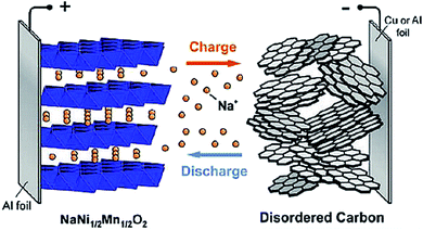 | ||
| Fig. 2 Schematic of sodium ion batteries with a layered transition metal oxide cathode and carbonaceous anode. Reproduced with permission23 © 2011, ACS Publications. | ||
Significant research on SIBs has so far been devoted to organic electrolytes because organic electrolytes can provide higher cell voltages. However, an area of interest to reduce the cost of SIBs is to utilize an aqueous electrolyte for SIBs since it would remove the need for ultra-dry fabrication and thus reduce material and assembly costs. The nonflammability of an aqueous system could provide better safety; and the overall performance may be improved due to high conductivity of aqueous solutions which would, in turn, reduce internal resistance of the battery.4,24–33
In what follows, we will provide a comprehensive review of cathodes, anodes and electrolytes first, followed by in-depth discussion of the advancements and challenges in binders, additives, Na ion transport, and SEI formation. To assist readers in capturing the breadth and depth of cathode investigations, we have grouped cathodes in five categories according to their chemical compositions. These are oxides, sulfides and sulfates, phosphates, fluorides, and hexacyanoferrates. Similarly, anodes are divided into three groups, including carbonaceous materials, metals and alloys, and metal oxides. Electrolytes are grouped in three categories with organic, aqueous, and ionic liquid-based electrolytes.
3. Cathode materials
3.1 Metal oxides
Metal oxide cathode materials are promising candidates for SIBs because there are several processing techniques (e.g., sol–gel method, co-precipitation, solid state reaction, etc.) that can be used to obtain these stoichiometric layered structures. Many of these materials are nanosized which offer large surface area and short diffusion paths for ions during de/sodiation upon cycling. Carbon coating enhances conductivity and offers more homogeneous particle size with uniform structure. For most of the oxide materials, the amount of sodium deintercalated from the cathode material ranges from 0.5 to 0.85. This is dependent on the initial stoichiometry and phase transitions that occur with respect to the change in oxidation states of the metals within the active material. Understanding the electrochemical behavior of the active materials at these different stages will enable the determination of the acceptable Na content range for alkali ion layers.We will review oxides with a single transition metal component first to emphasize the roles of the crystal structure and redox couples in electrochemical reactions. This will then be followed by reviews of oxides with multiple transition metal components. The use of substitution or doping of other transition metals in the layered oxide structures can offer multiple advantages over oxides with a single transition metal component, including (1) better stability of the material, (2) increased capacity by adding more redox active substitutes, (3) removal of Jahn–Teller distortions, (4) reduction in volume change of the active material, and (5) higher cycling numbers with better capacity retention.
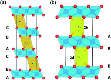 | ||
| Fig. 3 The crystal structure of (a) O3 and (b) P2 phases in AxMO2. Reproduced with permission4 © 2013, RSC Publishing. | ||
Sodium intercalation in NaxCoO2 bronzes was studied by Delmas et al.16 in the early 80s. They found that polymorphs of NaxCoO2 reversibly intercalated Na+ over a limited range of 0.5 ≤ x ≤ 1 for Na content and the phase transition that occurred was O3 → O′3 → P′3 for the initial O3–NaCoO2.2,4,16
NaxMnO2 has been widely studied for use as a cathode in SIBs.2–4,7,9,14,29,35–47 Two phases exist for this material, low temperature α-NaMnO2 is most stable and has an O3 layered structure with monoclinic structural distortion, and high temperature β-NaMnO2 is orthorhombic and contains MnO2 sheets which consist of edge sharing doubly stacked MnO6 octahedra. Ma, et al.36 found that 0.85 Na can be deintercalated from monoclinic NaMnO2 with 0.8 intercalation of Na during cycling giving 185 mA h g−1 discharge capacity at a C/10 rate with 71% retention after 20 cycles. Fig. 4a and b show the voltage profiles for multiple cycles and the voltage profile upon de/intercalation.36
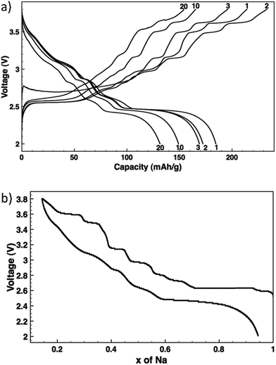 | ||
| Fig. 4 Voltage profiles: (a) NaxMnO2 cycled at C/10 with the cycle numbers indicated, and (b) NaxMnO2 de/sodiation as measured by potentiostatic intermittent titration. Reproduced with permission36 © 2012, The Electrochemical Society. | ||
These voltage profiles show distinct voltage steps and plateaus which indicate different intermediate phase transformations upon de/sodiation. XRD data of pristine NaMnO2 and partially charged NaMnO2 to the midpoint of the 2.63 V plateau confirm a two phase transformation from ∼Na0.93MnO2 to ∼Na0.7MnO2, respectively. The Na0.7MnO2 phase contains six metal layers as opposed to the two layers in Na0.93MnO2 which can be due to Na vacancy ordering or modification of O3 stacking by oxygen layer gliding.36 Further research must be done in order to determine all phase transformations that occur at the voltage plateaus in the voltage profiles.
Billaud, et al.47 were able to achieve a high capacity of 190 mA h g−1 with β-NaMnO2 at a rate of C/20. This material exhibits good rate capability and capacity retention when cycled at 2 C initially offering a discharge capacity of 142 mA h g−1 with ∼70% (100 mA h g−1) retention after 100 cycles. This compound has a complex structure which contains intergrown regions of α-NaMnO2 and β-NaMnO2 polymorphs.47 Upon cycling and lowering of the Na content, an increase in stacking faults caused the collapse of the long range order within the material, but was recovered upon Na reinsertion and maintains stable cyclability, even though β-NaMnO2 exhibits increased disorder. This is in contrast to common expectation requiring minimal structural change for reproducible stable cycling.47
Jo, et al.37 investigated the electrochemical behavior of α-NaMnO2 in two different electrolytes, 1 M NaBF4 tetraethyleneglycol dimethylether (TEGDME) and 1 M NaClO4 ethylene carbonate/diethyl carbonate (EC/DEC). The TEGDME electrolyte has a lower discharge capacity initially (136 mA h g−1) compared to that of the EC/DEC electrolyte but is more stable because after the 20th cycle it retained 74% capacity, whereas EC/DEC only retained 71.6%. The coulombic efficiency maintained over 90% for 1 M NaBF4 in TEGDME, while that of 1 M NaClO4 in EC/DEC consistently decreased to 80% within 20 cycles. Using EC/DEC offers small bulk and interfacial resistance, but TEGDME has more stable interfacial resistance allowing stable cyclability compared to EC/DEC.37
Single crystalline sodium manganese oxide (Na0.44MnO2) nanowires are an orthorhombic lattice structure.29 This structure contains MnO5 square pyramids and MnO6 octahedra which form large S shaped tunnels and smaller pentagon tunnels. The S shaped tunnels in Na0.44MnO2 allow mobility of Na ions that can be reversibly extracted and produce a theoretical discharge capacity of 121 mA h g−1, whereas Na ions are fixed in the pentagonal tunnels and are unable to be extracted. Na0.44MnO2 is a promising cathode material because it has a high capacity of ∼120–130 mA h g−1 with good cycle performance having 77% retention after 1000 cycles and is capable of being used in non-aqueous and aqueous electrolytes.29,31,35
Cao, et al.29 prepared homogeneous and highly crystalline Na0.44MnO2 nanowires and found that they are capable of inserting and extracting four Na ions during cycling inducing a chemical transformation from Na6Mn9O18 to Na2Mn9O18. This material delivers reversible capacities of 128 mA h g−1 at 0.1 C and 82 mA h g−1 at 2 C. The nanowires are mechanically stable and provide a short diffusion path for de/sodiation. This higher than theoretical capacity result may be due to Na extraction from the pentagonal smaller tunnels.29 Through density functional theory, XRD measurements, and electrochemical cycling, Kim, et al.35 were able to confirm this. There are three binding sites for Na0.44MnO2, Na1 corresponds to the almost filled small tunnel, while Na2 and Na3 are half filled in the S shaped tunnels. The Na2 site is broken up into Na21 and Na22 due to different orientation coordination as depicted in Fig. 5.35
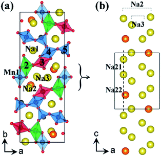 | ||
| Fig. 5 (a) Crystal structure of Na0.44MnO2 showing Mn and Na binding sites, and (b) the S shaped tunnel configuration along c-axis with different sodium positions Na21 and Na22 in Na0.44MnO2. Reproduced with permission35 © 2012, ACS Publications. | ||
Na21 sites are more stable than Na22 sites since Mn2 and Na2 distance is elongated from repulsive interaction of Na+ and Mn4+ ions. The Na22 sites are only prevalent between Na0.44MnO2 and Na0.55MnO2 due to the competing electrostatic interaction. This forms an unstable biphasic region which induces capacity fading and slow diffusion of Na ions. Seven intermediate phases were identified for sodium insertion and extraction. It was found that the order of extraction started at Na3 sites where sodium ion repulsion is the greatest followed by Na2 and Na1 sites.35 The results are shown in Fig. 6.35
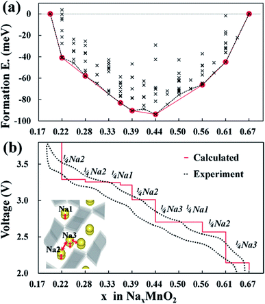 | ||
| Fig. 6 (a) Formation energies of seven stable intermediate phases during NaxMnO2 cycling calculated from 156 different sodium configurations, and (b) experimental and calculated voltage profiles for NaxMnO2 with respect to the minimum energy path of formation energies. Reproduced with permission35 © 2012, ACS Publications. | ||
Kim, et al.35 also researched the degree of volume change and evolution of lattice parameters of Na0.44MnO2 during charging and discharging processes. They found that the asymmetric change of lattice parameters is due to Jahn–Teller distortions and calculated that 44% substitution of Cr into Na0.44MnO2 would reduce volume change by 50%.
The intercalation of sodium into layered NaCrO2 has been studied for use in SIBs.17,48–51 Its rhombohedral (R![[3 with combining macron]](https://www.rsc.org/images/entities/char_0033_0304.gif) m) O3 type layered structure is similar to that of LiCrO2 but behaves differently since it is electrochemically active with reversible capacities of 120 mA h g−1 for the Na‖NaCrO2 cell (Fig. 7a).48 NaCrO2 was able to reversibly deintercalate 0.5 mole of sodium ions per formula unit to form Na0.5CrO2 giving the phase transitions of hexagonal O3 → monoclinic O3 → monoclinic P3 for the charge process. Irreversible Li intercalation of LiCrO2 is due to irreversible migration of Cr(VI) into tetrahedral sites due to disproportionate transfer of Cr(IV) to Cr(III) and Cr(VI). In NaCrO2, Cr(IV) cannot migrate due to the mismatch between CrVIO42− and the O–O bond length and CrO2 slab distance of the interstitial tetrahedron. Magnetic measurement confirmed that chemically deintercalated Na1−xCrO2 contained Cr(IV).48,52
m) O3 type layered structure is similar to that of LiCrO2 but behaves differently since it is electrochemically active with reversible capacities of 120 mA h g−1 for the Na‖NaCrO2 cell (Fig. 7a).48 NaCrO2 was able to reversibly deintercalate 0.5 mole of sodium ions per formula unit to form Na0.5CrO2 giving the phase transitions of hexagonal O3 → monoclinic O3 → monoclinic P3 for the charge process. Irreversible Li intercalation of LiCrO2 is due to irreversible migration of Cr(VI) into tetrahedral sites due to disproportionate transfer of Cr(IV) to Cr(III) and Cr(VI). In NaCrO2, Cr(IV) cannot migrate due to the mismatch between CrVIO42− and the O–O bond length and CrO2 slab distance of the interstitial tetrahedron. Magnetic measurement confirmed that chemically deintercalated Na1−xCrO2 contained Cr(IV).48,52
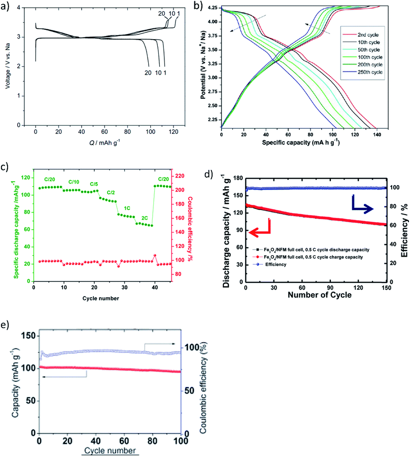 | ||
| Fig. 7 Charge–discharge profiles of (a) NaCrO2 (reproduced with permission48 © 2010 Elsevier) and (b) Na0.45Ni0.22Co0.11Mn0.66O2 (reproduced with permission61 © 2013, ACS Publications). Discharge capacities with respect to the cycle number of (c) Na2/3Co2/3Mn2/9Ni1/9O2 (reproduced with permission63 © 2014, Elsevier), (d) Na[Ni0.25Fe0.5Mn0.25]O2 (reproduced with permission62 © 2014, ACS Publications), and (e) NaNi0.5Ti0.5O2 (reproduced with permission66 © 2014, RSC Publishing). | ||
Unfortunately, capacity fading of this material does occur. Ding, et al.50 used carbon coating on the surface of active NaCrO2 particles to improve electrochemical behavior during cycling. Initial charge and discharge capacities of carbon coated NaCrO2 were 135 mA h g−1 and 116 mA h g−1, respectively. The discharge capacity only decreased to 110 mA h g−1 after the 40th cycle; whereas naked NaCrO2 had a discharge capacity of ∼105 mA h g−1 with 0.32% capacity loss for each cycle. The improved performance can be related to the carbon coating since it provides (1) decreased polarization of the electrode, (2) enhanced conductivity, (3) suppression of side reactions between the active material and electrolyte, and (4) slowing of SEI formation at the electrode surface.50
Overall, NaCrO2 is determined to be a safe electrode material since it is more stable in 1 M NaPF6 in EC/DEC than delithiated Li0.5CoO2 and LiFePO4.51 The reason for this is due to its high thermal stability. Accelerating rate calorimetry experiments showed lack of heat evolution in Na0.5CrO2. An exothermic reaction did not occur for this material until 250 °C with very little release of heat. Thermogravimetric analysis (TGA) showed very small mass change attributing to very little oxygen release. They determined that a reaction between the solvent and Na0.5CrO2 transforms into NaCrO2 and P3–CrO2−δ which gives minimal oxygen release and accounts for the high thermal stability of this material.51
NaFeO2 has been considered as a SIB cathode.53–58 Zhao, et al.56 show that it is a thermally stable material with stable reversible capacity of 85 mA h g−1 in a Na‖NaFeO2 battery. Differential scanning calorimetry (DSC) measurements showed less heat generation at higher exothermic onset temperatures (220–300 °C) offering thermal stability comparable to LiCoO2 counterparts.56 Recently, hollow iron oxide nanoparticles have been utilized for sodium ion transport. Hollow γ-Fe2O3 has cation vacancies which can serve as hosts for Na ions in a voltage range of 1.1–4.0 V. The γ-Fe2O3 has been encapsulated between layers of carbon nanotubes and exhibited a reversible capacity of 189 mA h g−1 with 99% coulombic efficiency. An increased C rate of 50 (3000 mA g−1) offered a capacity of 99 mA h g−1 with capacity retention for more than 500 cycles.59
Na0.45Ni0.22Co0.11Mn0.66O2 can be synthesized using co-precipitation61 or a solid state reaction.65 Buchholz et al.61 found that water treatment rinsing of the co-precipitated material enhances electrochemical performance by stabilizing de/sodiation. The O2 type phase transition along the 4.2 V voltage plateau of Na0.45Ni0.22Co0.11Mn0.66O2 is highly reversible and results in high capacities, high average voltage, and superior cycling performance with a specific capacity of 135 mA h g−1 and a coulombic efficiency exceeding 99.7% for more than 250 cycles (Fig. 7b).65
Na0.45Ni0.22Co0.11Mn0.66O2 was tested in an ionic liquid (IL)-based 10 mol% sodium bis(tri-fluoromethanesulfonyl)imide (NaTFSI) in N-butyl-N-methylpyrrolidinium bis(fluorosulfonyl)imide (PYR14FSI) electrolytic solution and carbonate-based (0.5 M NaPF6 in propylene carbonate) electrolyte.65 The ionic liquid electrolyte offers higher reversibility for electrochemical de/sodiation due to higher electrochemical stability of the ionic liquid which enables high potential P2–O2 phase transitions at 4.2 V and also hinders solubility of Mn into the electrolyte, offering improved performance at low potentials (2.2 V). A uniform SEI layer formed in batteries tested with the IL-based electrolyte which was beneficial for active material performance, leading to high specific capacities of ∼200 mA h g−1 and high average voltage (2.7 V vs. Na/Na+) with capacity retention of about 80% after 100 cycles.65
Nax[FeyMn1−y]O2![[thin space (1/6-em)]](https://www.rsc.org/images/entities/char_2009.gif) 60,68–70 has gained increased interest as a cathode material because it can obtain the O3 or P2 type structure depending on the sodium/(iron and manganese) ratio. P2 type Na2/3[Fe1/2Mn1/2]O2 delivers 190 mA h g−1 (∼520 W h kg−1) of reversible capacity with an average of 2.75 V vs. Na by utilizing both the Mn3+/Mn4+ and Fe3+/Fe4+ redox.60,70 The capacity lowers to ∼150 mA h g−1 after 30–40 cycles.60,71 In comparison to lithium, sodium is strongly ionized and has lower covalency with oxygen, thus the iron and oxygen gain more net electrons. The Fe3+/Fe4+ redox is accessible without oxygen loss due to the lower electrochemical potential of the redox reaction, approaching that of Na/Na+.60,70
60,68–70 has gained increased interest as a cathode material because it can obtain the O3 or P2 type structure depending on the sodium/(iron and manganese) ratio. P2 type Na2/3[Fe1/2Mn1/2]O2 delivers 190 mA h g−1 (∼520 W h kg−1) of reversible capacity with an average of 2.75 V vs. Na by utilizing both the Mn3+/Mn4+ and Fe3+/Fe4+ redox.60,70 The capacity lowers to ∼150 mA h g−1 after 30–40 cycles.60,71 In comparison to lithium, sodium is strongly ionized and has lower covalency with oxygen, thus the iron and oxygen gain more net electrons. The Fe3+/Fe4+ redox is accessible without oxygen loss due to the lower electrochemical potential of the redox reaction, approaching that of Na/Na+.60,70
O3 type Na[Fe1/2Mn1/2]O2 is electrochemically active and offers ∼110 mA h g−1. This material exhibits a large amount of polarization above 1 V between the oxidation and reduction processes when cycled vs. Na/Na+ in the voltage range of 1.5–4.2 V. Although P2 type Nax[FeyMn1−y]O2 is a promising material, some drawbacks exist: (1) large volume change (11.3% shrinkage after charge to 4.2 V) during electrochemical cycles, (2) restriction of sample handling in moist air due to hygroscopic nature (as-prepared P2–Na2/3[Fe1/2Mn1/2]O2 is somewhat oxidized by water, forming P2–Na1/2[Fe1/2Mn1/2]O2 and NaOH), and (3) sodium deficiency in the as-prepared sample.60,70
Na0.67(Mn1−xMgx)O2 where x ≤ 0.2 has a P2 type structure has been utilized in a SIB and offers a discharge capacity of 175 mA h g−1 (x = 0.05).72 The Mg within the material smooths charge–discharge profiles and cycling stability improves with increased Mg content. This substitution also reduces polarization of the cell.72
A layered, stable Na2/3Co2/3Mn2/9Ni1/9O2 was prepared by sol–gel method which belongs to the P63/mmc space group and adopts the P2-type structure.63 The cathode material delivered a capacity of 110 mA h g−1 when cycled from 2.0 to 4.2 V vs. Na/Na+ with coulombic efficiency exceeding 99.4%. The initial capacity was fully recovered when cycled first at the rate of C/20, then C/10, C/5, C/2, 1 C, 2 C, and finally C/20 again, demonstrating that this material has good rate capability and cycle stability (Fig. 7c).63 XRD analysis determined that a transition from the P2 to O2 phase occurred when the concentration of Na reached ∼1/3, but this was not confirmed in CV data since this transition would occur at ∼4.2 V which was the cutoff voltage for testing. Charge–discharge cycling was then tested between voltages of 2.0–4.5 V, and though the initial capacity increased, there was a large amount of capacity fading as cycling continued which can be attributed to electrolyte decomposition at higher voltage.63
Na[Ni0.25Fe0.5Mn0.25]O2 (NFM) was placed in a battery with a carbon coated Fe3O4 (C-Fe3O4) conversion anode and NaClO4 in fluoroethylene carbonate (FEC) and ethyl methanesulfonate (EMS) electrolyte.62 This group found that 1 M NaClO4 in EMS + 2 vol% FEC provided anodic stability of the electrolyte up to 5.6 V vs. Na/Na+. Moreover, the loading of Fe3O4 is higher than carbon since its density (5.17 g cm−3) is more than twice that of amorphous carbon (1.8 g cm−3) primarily used as anodes in SIBs. This translates to an increase in energy density of Fe3O4 compared to hard carbon. Both NFM and C-Fe3O4 electrodes were also separately paired with a Na electrode and charged–discharged at 0.1 C. Each electrode showed promising results with 200 mA h g−1 for C-Fe3O4 and 140 mA h g−1 for NFM.62
Upon charging, the P3 type monoclinic phase is formed and the desodiation proceeds with different transition metals exhibiting different changes in the average oxidation states.62 Ni2+ converts to Ni4+ and Fe3+ to Fe4+ at the end of charge, but almost no change occurs for the oxidation state of Mn. The combined cell of C-Fe3O4‖NFM operated at ∼2.4 V and delivered a capacity of 130 mA h g−1 (Fig. 7d).62 The structural stability and high electric conductivity of the electrode materials support the rate capability and cycling of this unique battery. The capacity retention was 76.1% at the 150th cycle with coulombic efficiency close to 100%.62
Yuan, et al.67 synthesized P2-type Na0.67Mn0.65Fe0.2Ni0.15O2 using a sol–gel method. This stoichiometry improved initial capacity to 208 mA h g−1 with 71% capacity retention over 50 cycles. The Ni substitution alleviates Jahn–Teller distortion of Mn(III) and has higher redox reversibility, thereby increasing reversible capacity and stability of the active material.67
The electrochemical performance of a novel titanium-based O3-type NaNi0.5Ti0.5O2 was explored for the first time as a cathode material. It offers reversible structural change upon de/sodiation.66 A Na‖NaNi0.5Ti0.5O2 cell operated at an average potential of 3.1 V vs. Na/Na+ and delivered a reversible capacity of 121 mA h g−1 at the current density of 20 mA g−1 (0.2 C). Cycling at an increased rate of 5 C delivered more than 60% of the initial discharge capacity, showing that this material has excellent cycle stability and rate capability.66 Fig. 7e shows the specific capacity and coulombic efficiency of NaNi0.5Ti0.5O2 as a function of cycle number, exhibiting less than 5% capacity reduction after 100 cycles.66
3.2 Sulfides/sulfates
Sodium sulfur batteries exist in molten form (270–350 °C) and have been widely used for load leveling and emergency power applications due to their high energy efficiency. The sulfur, sodium, and polysulfide materials are highly corrosive, therefore it is imperative that the seals and containers used for these batteries are resistant and offer protection from water and oxidizing environments. In September 2011 sodium sulfur batteries caught fire at NGK Insulators, Ltd. in Japan. Battery manufacture was suspended until June 2012 after determining the cause of the fire.1,9The high temperature and safety issues from use of these batteries have brought attention to the research of room temperature sodium sulfur batteries. Cathodes containing sulfur composites,73,74 Cu2S,75 FeS2,76 Ni3S2 and Ni3S2 with Fe additive,77,78 NaFeSO4F,79 and Na2Fe2(SO4)3![[thin space (1/6-em)]](https://www.rsc.org/images/entities/char_2009.gif) 80 are some of the materials studied for use in this type of batteries. The main issues that arise with sulfur containing cathodes are the low utilization of active material, volume expansion upon de/intercalation of Na ions, and polysulfide dissolution into the electrolyte; which are similar to those of Li–S batteries. They also have rapid capacity fading. Researchers have tried to produce Na–S batteries despite these disadvantages due to the high energy density this type of battery is capable of (760 W h kg−1).
80 are some of the materials studied for use in this type of batteries. The main issues that arise with sulfur containing cathodes are the low utilization of active material, volume expansion upon de/intercalation of Na ions, and polysulfide dissolution into the electrolyte; which are similar to those of Li–S batteries. They also have rapid capacity fading. Researchers have tried to produce Na–S batteries despite these disadvantages due to the high energy density this type of battery is capable of (760 W h kg−1).
Sulfur composite material consisting of sulfur embedded in a polyacrylonitrile matrix offered thermal stability by retaining above 90% of its original mass confirmed by TGA. This material reversibly reacted with sodium based on the following chemical reaction, 2Na + xS → Na2Sx. This material delivered a reversible specific capacity of ∼500 mA h g−1 up to 18 cycles but upon examination of the decrimped battery, dendrite formation occurred which would eventually short the battery.73
Cu2S, FeS2, and Ni3S2 with Fe additive offered initial specific capacities of 294 mA h g−1, 447 mA h g−1, and 400 mA h g−1 in low voltage potential regions of ∼2.0 V, respectively.75–77 These three studies only cycle these batteries for 15, 20, and 50 times. Although they have good coulombic efficiency, capacity fading after the first cycle occurred for these batteries with FeS2 having the worst electrochemical performance, displaying only ∼16% capacity retention. More stable, cyclable sulfide materials need to be studied for the Na–S battery system.
NaFeSO4F compound has a tunnel type structure and is ionically conductive (7.14 × 10⁻⁷ S3 cm−1) but only ∼0.07 Na was extracted from this structure electrochemically involving a 3.6 V FeII/FeIII redox plateau. Though extraction was possible, this material offered only ∼6% of its theoretical capacity.79
Na2Fe2(SO4)3 has the most promising results being operable at a voltage of 3.8 V and offering a reversible capacity of over 100 mA h g−1 and have 50% capacity retention at a high rate of 20 C.80 The Na2Fe2(SO4)3 is an entirely new material with never reported structure and composition. It is the first sulfate compound with a 3D alluaudite framework and large tunnels along the c-axis (Fig. 8a).80 Corner sharing bridges together Fe2O10 dimer and SO4 units. The dimers are formed by Fe ion occupation of edge sharing octahedral sites with crystallographically equivalent octahedron. The sodium ions occupy three specific crystallographic sites, as shown in Fig. 8a.80 The electrochemical data of this material is shown in Fig. 8b.80 This research is the first to obtain the highest known capacity for a Fe-based insertion compound at a high voltage of 3.8 V, making it comparable with Li ion systems. The de/intercalation of all Na sites in this material offers fast Na transport and excellent kinetics providing a battery with cyclic stability (Fig. 8b).80
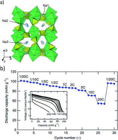 | ||
| Fig. 8 (a) Na2Fe2(SO4)3 structure projected along the c axis, and (b) capacity retention upon cycling up to 30 cycles under various rate of C/20 (2 Na in 20 h) to 20 C. Reproduced with permission80 © 2014, Nature Publishing Group. | ||
3.3 Phosphates
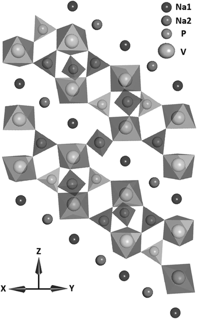 | ||
| Fig. 9 The crystal structure of Na3V2(PO4)3 in the a and b plane. Reproduced with permission81 © 2013, WILEY-VCH Verlag GmbH & Co. | ||
Saravanan, et al.81 synthesized Na3V2(PO4)3 nanograins in a conductive network using a novel synthesis method and reached 98.6% of the theoretical capacity of this material. Further, they found that it exhibited high capacity retention at high current rates and also displayed ultra-long life. The intercalation of two sodium ions due to facile sodium ion diffusion in Na3V2(PO4)3 particles accounted for the close to theoretical capacity achievement of the fabricated batteries, offering capabilities that nearly match that of lithium ion batteries.
Fig. 10 shows the electrochemical behavior of Na3V2(PO4)3 as a cathode material.81 Each CV has a high voltage peak at ∼3.37 V vs. Na+/Na and corresponds to the V4+/V3+ redox couple. Higher scan rates show a splitting of the cathodic peak at 3.3 V. This may be due to induced local heating at higher scan rates which in turn could lead to structural rearrangement of Na ions from the Na(1) to the Na(2) site. A maximum capacity of 116 mA h g−1 was reached at the 0.1 C rate. At the 10 C rate, 92.2% of the capacity was retained and as the rate increased to 20 C and 40 C, the retention was 80% and 54%, respectively.
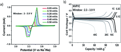 | ||
| Fig. 10 (a) Cyclic voltammogram of Na3V2(PO4)3, and (b) galvanostatic charge and discharge profiles for several C rates. Reproduced with permission81 © 2013, WILEY-VCH Verlag GmbH & Co. | ||
Jung, et al.88 used a combination of sol–gel method and solid state reaction to synthesize crystalline Na3V2(PO4)3 (NVP) on a graphene sheet surface (NVP/graphene) in order to enhance conductivity. When compared to naked NVP, this composite material exhibited better capacity retention at higher C rates and offers a smaller polarization between charge and discharge curves. The graphene sheets provide a conductive support and offer pathways for ion transport. The stable crystal framework structure of the NVP/graphene composite provides good cyclability and ∼96% capacity retention at a 10 C rate after 300 cycles.88
Ultrasonic template free spray pyrolysis method was used to form carbon coated hollow 500 nm diameter Na2FePO4F spheres with 80 nm wall thickness.91 Using a low rate of 0.1 C, the cathode delivered 89 mA h g−1 capacity. At 1 C, it offered 75 mA h g−1 capacity and provided 80% of this initial capacity after 750 cycles. An increased rate to 9 C maintained 33% of capacity. Electrolyte penetration into the nano-sized porous hollow C/Na2FePO4F spheres allows the electrochemical reaction to take place on both the outside and inside surfaces of the spheres as well as in the pores. Further, the C/Na2FePO4F hollow spheres offer a large reaction area with shortened Na+ diffusion length. The carbon coating provides structural stability which accommodates volume change during Na+ insertion–extraction, and electrical conductivity, thus improving charge transfer reaction kinetics and cyclability.91
Lu, et al.92 used a solid state reaction to produce NaVPO4F for use in a SIB. The cell voltage of a battery made of this material mixed with carbon is increased due to the high potential of the V3+ to V4+ redox transition. The NaVPO4F/C composites (5 wt% carbon) were tested in the voltage range of 2.5–4.2 V. The NaVPO4F/C composite gave a maximum discharge capacity of 97.8 mA h g−1 and had a capacity retention of 81% after 20 cycles. The amount of carbon used for mixing affected the overall performance of the battery, where too much or too little offered low capacity with increased degradation as compared to 5 wt% of carbon used with NaVPO4F. Too much carbon caused large particle size, thereby lengthening the pathway for sodium ion diffusion, making Na de/intercalation from the NaVPO4F material more difficult.92
Na1.5VPO4.8F0.7 was prepared using a solid state method and generated particles that ranged from 1–5 micron composed of a single crystalline domain.94 This cathode material is a pseudolayered structure with a space group P42/mnm. Sodium ion insertion into interstitial sites is provided by the three dimensional open framework of Na1.5VPO4.8F0.7 due to corner-sharing between PO4 tetrahedral and VO5F/VO4F2 octahedral units. The two types of vanadium local environment led to a mixed valence state of vanadium where V4+ and V3+ ions coexist which offers a tailored vanadium redox couple (V3.8+/V5+). The multi-electron redox reaction (1.2e− per formula unit) and the high potential (∼3.8 V vs. Na+/Na) of the vanadium redox gave an energy density of 600 W h kg−1 with ∼95% capacity retention for 100 cycles and ∼84% for an extended 500 cycles. This energy density is one of the highest densities ever reported for SIBs.94
Sodium vanadyl fluorophosphate [Na(VO)2(PO4)2F] materials are prepared using solvothermal methods99–101 capable of extracting 2 Na per unit formula reaching specific capacities of ∼100–110 mA h g−1.99,100 Two voltage plateaus which occur reversibly at 3.6 V and 4.0 V vs. Na/Na+ signify this. Serras, et al.99 reached the upper limit of this range due to carbon coating of the material which enhanced its electrochemical performance. Impregnation of carbon onto the surface through long thermal treatment resulted in a two phase material consisting of Na3(VO)2(PO4)2F and Na3V2(PO4)3 which offered an extra plateau at 3.3 V characteristic of the Na3V2(PO4)3 phase. It is well known that it is difficult for Na3(VO)2(PO4)2F to access its third Na per formula unit, but Xu, et al.100 have used theoretical calculation to determine how to alleviate this problem. They suggest the substitution of oxygen with Cl to form Na3V2Cl2(PO4)2F which would increase the energy density to 758 W h kg−1.
Investigation of Na3MnCO3PO4 has found that this cathode can exhibit a two electron intercalation reaction upon electrochemical cycling via Mn2+/Mn3+ and Mn3+/Mn4+ redox reactions with a high theoretical capacity of 191 mA h g−1.105 However, Chen, et al.105 were only able to obtain a low specific capacity of 125 mA h g−1 experimentally. Recently, Wang, et al.106 have been able to obtain high specific capacities, reaching 92% of the theoretical capacity of Na3MnCO3PO4 when aided by the addition of 60 vol% carbon black (CB), which provides a continuous CB network interacting with almost all Na3MnCO3PO4 particles. These findings show that as long as the low electronic conductivity of this material is alleviated, Na3MnCO3PO4 has great potential to be a viable cathode material for SIBs.106
Na7V4(P2O7)4PO4 or VODP was used in a SIB and offered unprecedented cyclic stability and capacity retention for over 1000 cycles.108 This material only extracted 3.5 and 3.3 Na ions per formula unit obtaining charge and discharge capacities of 81.5 mA h g−1 and 77.1 mA h g−1, respectively.108 Charging–discharging profiles of this material show that only 1 peak exists for discharging and two separate peaks for charging. Quasi open circuit potential confirmed that this behavior is attributed to different kinetics. Further analysis by XRD and DFT calculations proved that a reversible phase transformation of VODP occurs during Na de/intercalation and is the origin of the single valued voltage behavior of this battery. This intermediate phase is governed by the occupation of Na1 and Na2 sites and their relative stability. The structural transformation that occurs is a rotation of each unit of (VP2O7)4PO4 as depicted in Fig. 11.108 It is suggested that the rotational behavior buffers differences in lattice parameters between initial and final phases of de/intercalated material. This is in turn beneficial for cell kinetics and overall stability of the material.
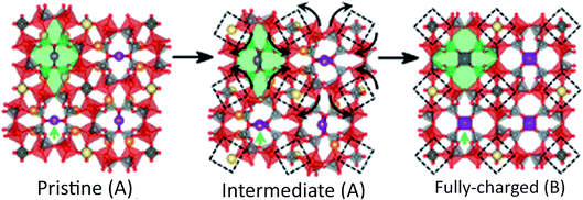 | ||
| Fig. 11 Structure rearrangement of VODP during phase transformation between pristine and charged phases. Crystallographically different sodium sites are colored with different colors (Na1, orange; Na2, violet; Na3, yellow). Reproduced with permission108 © 2014, PNAS Publishing Group. | ||
3.4 Fluorides
Sodium fluoroperovskites of the form NaMF3 (M = Ni, Mn, Fe) were produced using mechanochemical processes and investigated as cathode materials for SIBs.109,110 Dimov et al.110 investigated Fe, Cu and Ni metals but found that NaFeF3 is the most electrochemically active due to its chemical stability and iron's high affinity toward fluorine. Gocheva et al.109 were only able to obtain 61% of the theoretical capacity (197 mA h g−1) of NaFeF3, offering a reversible capacity of 120 mA h g−1 with a mean discharge voltage of 2.7 V. Nanosized (10–600 nm) NaFeF3 were produced using a liquid phase synthesis and exhibited discharge capacities in the range of 170–181 mA h g−1 when cycled at low rates of 0.01 C regardless of the size range.111 Smaller well dispersed NaFeF3 particles improved rate performance; and upon cycling at 0.1 C or greater offered higher discharge capacities when compared to larger agglomerated particles. Kitajou et al.112 used roll quenching and annealing to obtain highly crystalline NaFeF3. Their first cycle at a rate of 0.076 mA cm−2 between 1.5 V and 4.5 V gave 100% efficiency and provided a high initial discharge capacity of 197 mA h g−1.112 This is due to the reversible Fe2+/Fe3+ redox reaction confirmed by XPS. XRD data also confirmed that sodium insertion and extraction is possible due to the flexibility of the corner sharing matrix and the structural strength of the material.1123.5 Hexacyanoferrates
Prussian blue (A[FeIIIFeII(CN)6], A = Na+ or K+) and its analogues have been investigated as alkali ion hosts for use as a cathode material in a SIB.26,113–117 This material has a cubic face-centered structure in which two different metal centers Fe3+ and Fe2+ are bridged by CN− groups which provides large ionic channels along the 〈100〉 direction enabling facile insertion and extraction of alkali ions.26,114,115,118 Wessells, et al.26 were able to insert/extract sodium from nickel hexacyanoferrate in aqueous electrolyte, obtaining a capacity of ∼60 mA h g−1 at a C/6 rate. An 8.3 C rate showed no significant capacity loss after 5000 cycles giving a capacity of ∼52 mA h g−1.26 The retention of this material is promising, but the aqueous system requires low voltage which makes it only suitable for large scale EES.Yue, et al.118 synthesized mesoporous crystalline nickel hexacyanoferrate (NiHCF) using synergistically coupled nanocrystal formation and an aggregation mechanism. Different reaction times offer modification of surface morphology, porosity, and crystallinity. This group found that regardless of these characteristics a capacity of ∼65 mA h g−1 was achieved at low current rates with stable cycling. Using the longest reaction time gave macroporous NiHFC with a smaller surface area and offered the best rate performance, suggesting that larger pores within the structure facilitates more effective Na+ mass transport.118
Sodium manganese hexacyanoferrate NaMnFe(CN)6 was synthesized to form two different structures based on sodium content, Na1.72MnFe(CN)6 (NMHFC-1, rhombohedral) and Na1.40MnFe(CN)6 (NMHFC-2, cubic).114 This study compared these two products and found that the sodium ion content of precipitous aqueous solution during synthesis affects composition and structure of the final product. More Na+ concentration induces higher Na content and a transition from cubic to rhombohedral symmetry. This phase transition is reversible upon cycling; a fully discharged NMHFC-2 sample matches Raman spectra of pristine NMHFC-1 powder. NMHFC-1 has a high reversible capacity of 134 mA h g−1 and retains 120 mA h g−1 after 30 cycles due to FeIII/FeII and MnIII/MnII redox couples. Cycling of NMHFC-1 produces a potential shift where the final redox potential is higher for the FeIII/FeII, but lower for the MnIII/MnII couples. The power density and high rate capability of NMHFC-1 make it a promising cathode material.114
4. Anode materials
Unfortunately, sodium does not intercalate with graphite which is the most commonly used anode for Li based batteries. Several types of carbons have been investigated such as petroleum cokes,119–121 carbon microspheres,122 carbon black,123 fibres,124 and N-doped carbon nanofibers.125,126 Stevens and Dahn127 were able to insert sodium into hard carbon and since then, this material has been investigated extensively by several groups. In addition to carbonaceous materials, pure metals, metal alloys and oxides have been investigated in order to increase the specific capacity and cycle life of the anode. Pure metals and their alloys are attractive due to their high theoretical capacities but often suffer from the problem of pulverization. Oxides have only been investigated for the last 2 to 3 years, but have demonstrated cycle stability up to 450 cycles. Progresses made in these areas are detailed below.4.1 Carbonaceous
Sugar pyrolysis was used to prepare hard carbon (HC) with highest reversible capacity ever reported in the literature (300 mA h g−1 at a rate of C/10 after 120 cycles).129 This study focused on the effect of ball milling hard carbon as well as electrode processing atmosphere (air or Ar). The use of air or Ar for electrode slurry seemed to have no overall effect on the performance of the battery, suggesting that there is no significant impact on electrolyte decomposition and SEI formation, but also that the surface chemistry of the material is not modified either.
The as-synthesized and ball milled carbon were evaluated in additive free NaClO4 in EC:PC electrolytes. Though the ball milled hard carbon (PBMHC) had higher specific surface area and smaller particles, the as-synthesized hard carbon was more stable and gave a lower amount of heat generation based on DSC investigation. Therefore, it was beneficial with respect to safety as well. The evaluation of the degree of graphitization based on the integrated intensity of D/G (D = defect-induced D band, and G = crystalline graphite G band ratio of carbon) was found to be the determining feature that gave the difference in reversible specific capacities for these materials (2.6 and 2.1) for hard carbon and PBMHC, respectively.129
Hard carbon C1600 was used as an anode in a sodium ion battery and its electrochemical and thermal properties were tested in four different electrolytes: (i) 1 mol dm−3 NaClO4/EC:DMC, (ii) 1 mol dm−3 NaClO4/PC, (iii) 1 mol dm−3 NaPF6/EC:DMC, and (iv) 1 mol dm−3 NaPF6/PC.130 The C1600 performed best with 1 mol dm−3 NaClO4/EC:DMC giving an initial capacity of 413 mA h g−1 with retention of 90% over 50 cycles.130 Based on TGA/DSC testing done in a temperature range from RT to 400 °C, C1600 anodes were more thermally stable in EC:DMC based electrolytes. The onset temperatures of exothermic heat for sodiated C1600 in 1 mol dm−3 NaClO4/EC:DMC were lower than that of the lithiated electrode in the same electrolyte. This proves that this mixture of anode and electrolyte for Na batteries is more stable than that for Li ion batteries in spite of the instability of Na metal compared to Li.130
Hard carbon is an advantageous material to be used as an anode, but other carbonaceous materials have been studied as well. These materials are nanosized sheets,131 wires,132 or N-doped fibers125,126 with structural stability and interconnected networks which offer accommodation of volume expansion and good conducting connectivity.
Pyrolyzation of a hollow polyaniline nanowire precursor was performed to prepare hollow carbon nanowires (HCNWs).132 Cycling this material at a 0.2 C rate between 0.01–1.2 V delivered a high reversible capacity of 251 mA h g−1 with 82.2% capacity retention over 400 charge–discharge cycles.132 Na insertion into the carbon was obtained due to the size and structure of the HCNWs which offered short diffusion distances for Na ions, but the interlayer spacing (0.37 nm) between graphitic sheets also enabled good Na-insertion. Theoretical calculations revealed that a minimum spacing of 0.37 nm is needed for Na ion intercalation since the energy barrier for Na ion insertion (0.053 eV) is low enough to conquer. Na ions undergo two types of insertion–extraction mechanisms for this material. The voltage range of 0.2–1.0 V produced a reaction characterized by a charge transfer mechanism on the surface of the small graphitic clusters. The lower voltage range of 0.0–0.2 V mechanism was related to Na ion insertion–extraction in the graphitic interlayers.132
Introduction of a hetero atom into a carbonaceous anode material was proven beneficial for enhancing electrochemical performance in LIBs. This approach was used for SIBs where polypyrrole precursors were pyrolized in an inert atmosphere to obtain N-doped interconnected carbon nanofibers.125,126 N-doping generates extrinsic defects which can enhance reactivity and electronic conductivity of the carbon. O-containing and N-containing functional groups exist on the surface of the nanofibers. The redox reaction between functional groups and active sites on the surface of the carbon layer attribute to Na ion adsorption and desorption and electron transfer. Cycling of this material showed that a pseudocapacitance can be generated due to the interaction between the electrolyte and N species on the surface. An increased amount of pyridinic and quaternary nitrogen gives better electrochemical performance and higher pseudocapacitance. Overall the interconnected N-doped nanofibers offered large interlayer distance and enhanced Na ion transport which gave high rate capability and stable cyclability. The only drawback is the low average voltage of ∼1 V vs. Na/Na+, but these materials may still be considered due to their rate performance.125,126
4.2 Metals/alloys
Pure metals or metal alloys are attractive due to their high theoretical capacities but their main drawback is pulverization. The larger ionic radius of Na makes the effect of volume expansion upon de/sodiation more detrimental in causing irreversible structural changes to the anode. Continued cycling often compromises the structure of the Na host and leads to rapid cycle fading.133–138 Some metals (Sn and Sb) form binary alloys with sodium and have been known to aggregate and alloy into larger particles isolating in the electrode and further disrupting the integrity of the material. Sn or Sb based anodes133,135–137 with specific structural properties are introduced which aid in the reduction of aggregation, and also buffer volume expansion upon cycling with sodium.The mechanical behavior of crystalline Na–M (Sn, Pb, Si, and Ge) alloys were investigated by Mortazavi, et al.138 using first principles simulations to determine their intrinsic elastic properties during sodium intercalation. The elastic moduli of pure M phases changed by 75% from sodiation. The elastic moduli decreased linearly with Na concentration. This elastic softening originated from a transition to weaker interatomic bonding. Na–Si and Na–Ge have low values for the BH/GH ratio which indicates low resistance toward brittle failures; therefore, these alloys would be susceptible to fracture upon sodiation. The electronic charge distribution analysis for each system reveals that upon sodiation M–M bonds are replaced with ionic Na–M bonds.138
The structural stability of the material upon sodiation is at risk, but it is important to understand the behavior of these alloys in order to fabricate Na-ion electrode architecture that can improve the mechanical stability of these materials. The functional relationship between Na+ concentration and elastic moduli can be used to determine deformation and fracture of these materials using simple continuum models.138 Some unique metal or metal alloys produced by using novel techniques to fabricate a material that was capable of handling volume expansion and improving cyclic stability are reviewed below.
High energy ball milling of red phosphorus powder with Super P carbon black at a ratio of 7![[thin space (1/6-em)]](https://www.rsc.org/images/entities/char_2009.gif) :
:![[thin space (1/6-em)]](https://www.rsc.org/images/entities/char_2009.gif) 3 for 24 hours produced an amorphous nanocomposite sample with highly dispersed phosphorous clusters in a carbon matrix.134 This structure can buffer the 490% volumetric expansion of phosphorus to Na3P upon conversion-type reaction with 3 Na atoms. The fully charged Na3P form Na2P, NaP, and NaP7 intermediates during charge–discharge cycling. The initial discharge capacity was 1750 mA h g−1 with stable reversible capacity during the first 40 cycles. The capacity gradually dropped to ∼1200 mA h g−1 but with 99% coulombic efficiency.134 Increased current density to 4000 mA g−1 resulted in charge capacity loss at the low voltage plateau of 0.2 V. Electrochemical impedance spectra revealed that the charge transfer resistance of sodium ion insertion was ten times higher than that of the extraction process for this material. When fully charged using a current density of 250 mA g−1, the material is easily discharged at several rates and can maintain about 95% of its potential capacity.134
3 for 24 hours produced an amorphous nanocomposite sample with highly dispersed phosphorous clusters in a carbon matrix.134 This structure can buffer the 490% volumetric expansion of phosphorus to Na3P upon conversion-type reaction with 3 Na atoms. The fully charged Na3P form Na2P, NaP, and NaP7 intermediates during charge–discharge cycling. The initial discharge capacity was 1750 mA h g−1 with stable reversible capacity during the first 40 cycles. The capacity gradually dropped to ∼1200 mA h g−1 but with 99% coulombic efficiency.134 Increased current density to 4000 mA g−1 resulted in charge capacity loss at the low voltage plateau of 0.2 V. Electrochemical impedance spectra revealed that the charge transfer resistance of sodium ion insertion was ten times higher than that of the extraction process for this material. When fully charged using a current density of 250 mA g−1, the material is easily discharged at several rates and can maintain about 95% of its potential capacity.134
Unique nanorods with a core–shell structure composed of C/Sn/Ni were synthesized to form a 3D nanoforest binder free composite electrode.133 Vertical alignment of the rods with interdigital spacing accommodated volume expansion/contraction of the alloy during sodiation/desodiation. The carbon coating on the Sn layer of the nanorods improved electrochemical performance by providing conductivity and suppressing aggregation and pulverization of Sn during cycling. Fig. 12 demonstrates this unique structure and its electrochemical behavior.133 The electrochemical performance of this anode material was investigated in coin cells using Na metal as the counter electrode, and 1 M NaClO4 in ethylene carbonate/diethyl carbonate (EC![[thin space (1/6-em)]](https://www.rsc.org/images/entities/char_2009.gif) :
:![[thin space (1/6-em)]](https://www.rsc.org/images/entities/char_2009.gif) DEC, 1
DEC, 1![[thin space (1/6-em)]](https://www.rsc.org/images/entities/char_2009.gif) :
:![[thin space (1/6-em)]](https://www.rsc.org/images/entities/char_2009.gif) 1 by vol%) as electrolyte. Sn anodes provided around 730 mA h g−1 at the first desodiation process and retained 55% initial capacity after 150 cycles.133
1 by vol%) as electrolyte. Sn anodes provided around 730 mA h g−1 at the first desodiation process and retained 55% initial capacity after 150 cycles.133
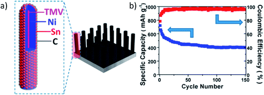 | ||
| Fig. 12 (a) Schematic illustration of the hierarchical structure of the 3D C/Sn/Ni/TMV1cys anode nanorod arrays, and (b) cycling performance of the 3D C/Sn/Ni/TMV1cys anode. Reproduced with permission133 © 2013, ACS Publications. | ||
Sn thin film deposition on a carbon nanotube coated hierarchical wood fiber substrate was utilized as an anode in SIBs, giving an initial discharge capacity of 339 mA h g−1 with ∼43% retention after 400 cycles.137 The ductility of the wood substrate (circumferential stiffness 0.7–3.0 GPa) enabled sodiation by releasing mechanical stress during cycling. The anodes were analyzed after 400 cycles in the fully charged state and a wrinkled structure on the wood fibers was observed. This surface change was correlated to fiber deformation and attributed to the improved cycling performance of the battery by reducing rupture of the SEI layer and minimizing exposure of the Sn to the electrolyte, thereby keeping the morphology of the Sn surface intact and preventing pulverization.137
The mesoporous structure of the fibers acted as an electrolyte reservoir, offering ion transport among all surfaces of the fibers and improving the kinetics of Na ion transport. Fig. 13a and b illustrate ion transport pathways and electrochemical activity with respect to blocked and unblocked pathways.137 The lightweight substrate of the wood fibers offered excellent mechanical properties, large surface area, and a porous structure which improved cycling stability and provided effective ion and electron transport.137
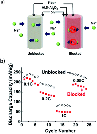 | ||
| Fig. 13 (a) Na ions transport along and diffuse through the mesoporous wood fiber structure. Internal transport pathways are blocked by the conformal Al2O3 coating, and (b) the rate performance of the Sn anode deposited on the carbon-coated mesoporous wood fibers. Reproduced with permission137 © 2013, ACS Publications. | ||
Sn nanoparticles were mixed with poly(9,9-dioctylfluorene-co-fluorenone-co-methylbenzoic ester) (PFM) conductive binder (Sn/PFM) and used in a sodium ion battery delivering 806 mA h g−1 and 610 mA h g−1 at C/50 and C/10 rates, respectively.135 PFM binder caused isolation of Sn nanoparticles, but due to its conductivity all nanoparticles were electrically conducting and able to reversibly cycle close to the theoretical capacity. The study only had 10 cycles for testing of each type of electrode. Initial results of the first ten cycles do correlate well to the suggested behaviors of the electrodes, but more cycling needs to be done in order to determine if the Sn/PFM is highly reversible with coulombic efficiency at several C rates over a long period of time.135
Electrospinning was used to create an antimony/carbon electrode with Sb nanoparticles of ∼30 nm which were uniformly encapsulated in interconnecting 1D 400 nm carbon fibers (SbNP@C). The Sb/carbon ratio was estimated to be 54 to 46 (in weight) based on TGA results. The electrode was completely binder free, and did not require a carbon additive for conductivity. This material was able to endure over 300 cycles under a current density of 100 mA g−1, maintaining an overall discharge capacity of 350 mA h g−1.136 The electrodes were able to handle high current density cycling and delivered total reversible capacities of 273, 185, 123, and 88 mA h g−1 at the current densities of 1.0, 2.0, 4.0, and 6.0 A g−1, respectively.136 Upon disassembly, SEM images showed that the SbNP@C electrode maintained its structural integrity and flexibility thereby withstanding expansion due to sodiation. The SbNP@C microstructure was also effective in stabilizing the SEI film. The Sb nanoparticles did undergo a transformation to even smaller amorphous particles, but remained within the carbon fiber core, thus confirming the mechanical stability of the fiber.
Based on the results of these experiments for metal and alloy anodes, the use of specialized structures of nanosize whether chemically synthesized or fabricated from a naturally sourced substrate are effective in accommodating volume expansion to buffer the stress in the anode from the de/sodiation process. Some of the results obtained are the first of their kind with respect to rate capability and is a marked improvement from previous studies. Further research needs to be done in order to cycle these materials at higher C rates with longer life.
4.3 Metal oxides
Xiong, et al.139 were one of the first groups to utilize an all oxide Na ion battery using TiO2 nanotubes as an anode and a Na1.0Li0.2Ni0.25Mn0.75Oδ as a cathode. The cell had an operating voltage of 1.8 V and a discharge capacity of ∼80 mA h g−1.139 This group found that the diameter of the nanotube (>80 nm ID) is critical for Na intercalation. Solvated Na ions are too large to infiltrate smaller diameter nanotube pores, and this size imbalance limits the capacity of the structure. TiO2 has been further studied in the form of nanocrystals,140 and microspheres141 as anodes in SIBs which have been able to successfully intercalate sodium ions.Anatase TiO2 nanocrystals were used as anodes in a sodium ion battery. They exhibited a stable reversible charge capacity of ∼150 mA h g−1 and could withstand high rate cycling of 2 A g−1 without degradation.140 The tetragonal crystal structure of anatase TiO2 offers pathways for Na diffusion as it is made up of 3D networks of stacked 1D zig zag chains which consist of distorted edge sharing TiO6 octahedra. This group tested the as synthesized material (ANC), but also prepared a TiO2/carbon composite (ANC-C) for battery testing and comparison. Each sample had particle sizes in the 10–15 nm size range with similar particulate morphology. The ANC-C sample gave lower capacity than ANC, but it was more efficient with less charge transfer resistance. The added carbon to the ANC-C nanoparticles offers conductivity, and a higher specific surface area enables a lot more diffusion of ions during cycling.
Carbon coated TiO2 microspheres141 were utilized as an anode in a SIB. The microspheres were primarily TiO2 crystallites whose growth was suppressed from carbon coating during calcination. The uniform carbon coating enhanced electrical conductivity while preventing agglomeration of the crystallites and thus shortening the diffusion paths for Na+ ions. The electrochemical properties were evaluated as a function of carbon content, and the TiO2–6.8 wt% C electrode exhibited the best cycle performance (100% cycle retention during the 50th cycle) and the best rate capability, delivering the discharge capacities of 155 mA h g−1 at 0.1 C, 149 mA h g−1 at 1 C, and 82.7 mA h g−1 at a 10 C rate, respectively.141
Na2Ti3O7 has been researched as a promising intercalation compound. Two dimensional sheets of Ti3O72− which share edges with triple octahedral chains accommodate Na ion transport.6,142–145 Rudola, et al.143 achieved 177 mA g−1 at a C/10 rate with relatively stable capacity retention.143 Zhang, et al.145 synthesized a three dimensional spiderweb architecture of Na2Ti3O7 nanotubes which offers charge capacity of 425 mA h g−1 (0.05 C rate), and can deliver 107 mA h g−1 (0.5 C rate) after 500 cycles with capacity loss of only 28% with coulombic efficiency of ∼100%. The use of P2 type layered Na2/3Co1/3Ti2/3O2 provides ∼90 mA h g−1 (0.2 C rate) of reversible capacity with ultrastable cyclability with 84.84% capacity retention for 3000 cycles (5 C rate), and structural stability (0.046% unit cell volume decrease) even after 500 cycles of sodium de/intercalation.146 A potential anode for grid scale applications whose structure facilitates sodium intercalation is Na2Ti6O13. It offers a capacity of 20 mA h g−1 (20 C rate) that is capable of cyclability of 5000 times with ∼75% capacity retention.147 TGA analysis also showed thermal stability with little weight loss until 500 °C making it a safe material for prolonged use in a grid system.
A copper oxide (CuO) nanowire array (CNA) was prepared using in situ engraving of Cu foil to produce a binder and additive free anode for use in a SIB (Fig. 14a).148 The aligned, porous, arrayed structure of the CNAs offered ample space for volume expansion during cycling which reduced pulverization. Further, this porous structure facilitated electrolyte diffusion and electron transport. The contact between the CNAs and the Cu current collector provided a framework for the electrochemical reaction to begin at the Cu substrate and spread to the whole electrode. This helped to retain morphological integrity of the CNAs. The in situ formed interconnected metallic Cu particles served as electron transporting paths between the Cu substrate and the unreacted CuO close to the tips of the CNAs.
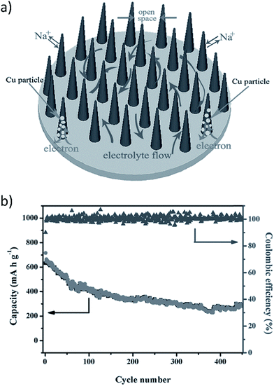 | ||
| Fig. 14 (a) Binder free CuO nanowire array (CNA) electrode, and (b) cycling performance of the binder free CNA (current density 200 mA g−1). Reproduced with permission148 © 2014, WILEY-VCH Verlag GmbH & Co. | ||
Fig. 14a and b show the schematic of the CuO arrays and the electrochemical behavior of binder free CNAs at a high current density of 200 mA g−1, respectively.148 A high initial discharge capacity of 640 mA h g−1 (close to the theoretical capacity of 674 mA h g−1) was obtained using a high current density of 200 mA g−1 which corresponds to 1.9 sodium ions per formula unit. XRD results indicated that reduction reactions during discharge were attributed to the conversion of CuO into intermediate phases (Cu1−xIICuxIO1−x/2, Cu2O) and the decomposition of Cu2O into Cu and Na2O.148 The anode exhibited good cycle stability up to 450 cycles. However, irreversible capacity loss did occur on the initial charge which could hinder practical application, but conductive coating or doping of the CNAs may alleviate this problem. Further research in this area must be employed.148
5. Electrolytes
Interfacial reactions between the electrolyte and electrode surfaces are a key factor in understanding SEI layer formation and charge transfer kinetics during cycling of sodium ion batteries. The investigation of different electrolytes for use in SIBs is essential in order to determine the optimal electrolyte composition for enhanced electrochemical performance of battery materials. The electrolytes studied so far can be broadly grouped into three categories: organic electrolytes, aqueous electrolytes, and ionic liquid based electrolytes. The progress made in these systems is summarized below.5.1 Organic electrolytes
Jang, et al.149 have investigated sodium perchlorate (NaClO4) salt mixed with binary solvents as electrolytes for SIBs. The electrolytes were 1 M NaClO4 dissolved in a solvent mixture of ethylene carbonate (EC)/diethylene carbonate (DEC) (1/1, v/v) (EC/DEC/1 M NaClO4), or ethylene carbonate (EC)/propylene carbonate (PC) (1/1, v/v) (EC/PC/1 M NaClO4). Galvanostatic cycling of a SIB with a Na4Fe3(PO4)2(P2O7) cathode was done between 1.7 and 4.2 V at a rate of C/20 for pre-cycling and C/10 for cycling.149 It is found that the PC based electrolyte which has a higher dielectric constant than DEC showed higher ionic conductivities with NaClO4 concentrations greater than 0.5 M and was stable at potentials up to 4.7 V vs. Na/Na+, whereas the DEC based electrolyte began oxidizing at 3.6 V on the stainless steel electrode used for this testing parameter. The decomposition of DEC forms organic radical species (CH2CH2˙) which then react with EC. The decomposition products accelerate decomposition of the electrolyte and diffuse to the cathode, creating a thick film. XPS measurements also confirmed that ClO4− anion decomposition was accelerated by these decomposition products. The EC/PC/1 M NaClO4 electrolyte offered more stable electrochemical performance of the Na4Fe3(PO4)2(P2O7) making it a better candidate for use in this SIB.149Ponrouch, et al.150,151 studied several different organic based electrolytes to determine the optimal electrolyte for a cell with hard carbon vs. Na anode. All tested electrolytes consisted of a 1 M salt: sodium bis(tri-fluoromethanesulfonyl)imide, sodium perchlorate, or sodium hexafluorophosphate (NaTFSI, NaClO4, or NaPF6, respectively) in: propylene carbonate (PC), ethylene carbonate (EC), diethyl carbonate (DEC), dimethyl carbonate (DMC), dimethoxyethane (DME), tetrahydrafuran (THF), or triethylene glycol dimethyl ether (Triglyme). The three salts were also tested in 50/50 wt% mixtures of EC:DMC, EC:DME, EC:PC, and EC:Triglyme. The group tested the viscosity, ionic conductivity, and stability (electrochemical and thermal) as well as their electrochemical performance.
It is found that there is improved ionic conductivity of mixed solvents with lower viscosity values than single solvent based electrolytes. In addition, the ionic conductivity is found to be proportional to the dielectric constant of the EC co-solvent except for PC and Triglyme which decrease ionic conductivity due to their increased viscosity. The use of a co-solvent therefore improves dissociation of a salt and enhances ionic conductivity.150 The thermal stability of the single solvents, binary solvents and salts were tested using DSC experiments. The NaClO4 was found to be the most stable followed by NaPF6 and NaTFSI. The trend for thermal stability of single solvents is PC > EC > DEC > DMC > DME. EC:PC was found to be the most thermally stable binary solvent. The electrochemical potential windows of each salt in PC as well as NaClO4 in all of the different single solvents and binary solvents are tested, and the results are shown in Fig. 15.150
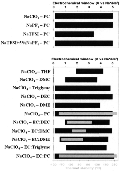 | ||
| Fig. 15 Electrochemical potential window stability of various salts with PC and NaClO4 in various solvents. Reproduced with permission150 © 2012, RSC Publishing. | ||
The EC:PC with NaPF6 was the optimal electrolyte to be used as a standard electrolyte in SIBs with hard carbon as the anode. Although the NaClO4 based electrolyte offered more stable cyclability giving a reversible capacity of ∼200 mA h g−1 with decent rate capability and over 180 cycles of capacity retention, the NaPF6 based electrolyte showed better SEI thermal stability with the highest exothermic onset temperature of 156.2 °C for full sodiation of hard carbon.150
This group went even further in their studies in a following report based on electrolyte optimization through the addition of a third low viscosity co-solvent.152 The viscosity and conductivity were analyzed using an EC:PC mixture with 1 M NaClO4, NaPF6, or NaTFSI and the addition of a co-solvent with a fixed composition of EC0.4:PC0.4:U0.2, U being either DEC, DMC, or DME. The introduction of these following co-solvents decreased viscosity and enhanced ionic conductivity following the trend: DME > DMC > DEC.152
NaTFSI salt was used in this study152 in order to determine cation–anion interaction based on salt solvation since the TFSI− anion is considered the best probe for solvation. The solvation shell of sodium cations is mainly composed of EC with very little contribution from the other solvents or anion. This showed that there is no significant modification to the solvation shell by DMC addition, and that increased ionic conductivity was due to the decrease in the viscosity of the electrolyte.
DMC content influence was further studied using EC:PC:DMC electrolyte with the NaTFSI salt using a difference of content from 0–50 wt% for DMC while the EC![[thin space (1/6-em)]](https://www.rsc.org/images/entities/char_2009.gif) :
:![[thin space (1/6-em)]](https://www.rsc.org/images/entities/char_2009.gif) PC ratio was maintained at 1
PC ratio was maintained at 1![[thin space (1/6-em)]](https://www.rsc.org/images/entities/char_2009.gif) :
:![[thin space (1/6-em)]](https://www.rsc.org/images/entities/char_2009.gif) 1. Based on the Arrhenius plot as shown in Fig. 16,152 it was found that the most thermally stable composition with respect to DMC content was EC0.45:PC0.45:DMC0.1. The ionic conductivity of the electrolyte with the small addition of DMC was improved over the whole range of temperatures used, making EC0.45:PC0.45:DMC0.1 the best electrolyte choice for use in testing HC and Na3V2(PO4)2F3 vs. Na/Na+ as well as in a full HC‖Na3V2(PO4)2F3 cell.
1. Based on the Arrhenius plot as shown in Fig. 16,152 it was found that the most thermally stable composition with respect to DMC content was EC0.45:PC0.45:DMC0.1. The ionic conductivity of the electrolyte with the small addition of DMC was improved over the whole range of temperatures used, making EC0.45:PC0.45:DMC0.1 the best electrolyte choice for use in testing HC and Na3V2(PO4)2F3 vs. Na/Na+ as well as in a full HC‖Na3V2(PO4)2F3 cell.
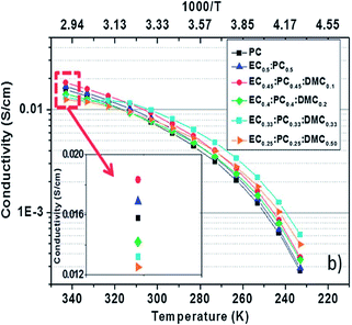 | ||
| Fig. 16 Arrhenius plots of the conductivity of the electrolyte based on 1 M NaTFSI salt dissolved in various solvent mixtures. Reproduced with permission152 © 2013, RSC Publishing. | ||
Full Na-ion cells had an operation voltage of 3.65 V, very low polarization, and excellent capacity retention upon cycling with reversible capacity of ∼97 mA h g−1 for more than 120 cycles with high coulombic efficiency (>98.5%).152 Fig. 17a and b show the voltage vs. capacity profiles of the full cell at different C rates and the insets show charge capacity and efficiency, as well as a schematic of the full cell.152
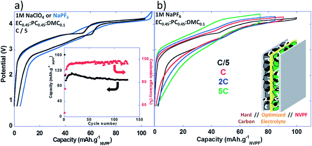 | ||
| Fig. 17 (a) Voltage versus capacity profiles for NVPF‖HC full Na-ion cells cycled in 1 M NaPF6 or 1 M NaClO4 in EC0.45:PC0.45:DMC0.1 recorded at C/5 (inset: charge capacity and coulombic efficiency versus cycle number (C/5; 1 M NaClO4 in EC0.45:PC0.45:DMC0.1)), and (b) voltage versus capacity profiles for NVPF‖HC full Na-ion cells cycled in 1 M NaPF6 in EC0.45:PC0.45:DMC0.1 recorded at different rates. Reproduced with permission152 © 2013, RSC Publishing. | ||
These studies150–152 have been very informative with respect to organic based electrolytes. This information is beneficial to the SIB community because there are not many other studies that are so in depth with respect to all of the different organic solvents and Na salts. Utilizing this information to accommodate the voltage potentials of active materials in a battery can offer optimized performance by choosing an optimal electrolyte.
5.2 Aqueous electrolytes
Among various studies of aqueous batteries,24–28,30,31 Na2SO4 in deionized water is a popular electrolyte, but other Na based salts such as NaCl and NaNO3 can also be used. Kim et al.31 found that the use of an aqueous electrolyte with Na0.44MnO2 gave better rate capability and kinetic behavior as opposed to non-aqueous electrolytes. This was due to the difference in the apparent diffusion coefficient (1.08 × 10⁻¹³ to 9.15 × 10⁻¹² cm2 s−1 in aqueous system and in the range of 5.75 × 10⁻¹⁶ to 2.14 × 10⁻¹⁴ cm2 s−1 in non-aqueous systems).31Na3V2(PO4)3 (NVP) in a three-electrode system was tested between 0 and 0.9 V vs. standard calomel electrode (SCE) in 1 M Na2SO4.30 Several factors such as (1) unwanted oxidation of H2O, (2) electrode material dissolution in aqueous electrolyte, and (3) structure variation of active material during de/intercalation have been identified that can cause performance decay of aqueous SIBs, leading to low capacity retention (∼32% at 30th cycle) and unsatisfactory coulombic efficiency of ∼80%.30
A full aqueous SIB was built using Na2V6O16·nH2O as anode and Na0.44MnO2 as cathode by Deng et al.27 They found that the diffusion of sodium ions was provided by pathways formed in the interstices between V3O8 layers where hydrated sodium ions are located. An irreversible structural change occurs upon sodium intercalation which caused rapid capacity fade of the battery.27
A promising aqueous battery system to date is composed of a Na0.44MnO2 cathode with a NaTi2(PO4)3 anode with 1 M Na2FesO4 electrolyte. This battery maintains ultrafast rate performance (>100 C) with cycling stability surpassing 1500 cycles.33 This cell delivers ∼120 mA h g−1 of reversible capacity. XRD results show each electrode retains structural stability even during high rate cycling. The battery is most stable at C >1. The capacity fade at low rates could possibly be related to partial dissolution of the electrodes, and oxidation of the anode or electrolyte.33
The use of an aqueous SIB would be very advantageous because of the huge abundance of Na resources, reduced cost, and safety; but there are drawbacks. The structural stability needs to increase in order to tolerate de/intercalation and stabilize capacity. Complications that arise with the use of aqueous batteries are (1) elimination of residual O2 in the electrolyte, (2) inhibition of H3O+ co-intercalation into the electrode, and (3) efficient internal consumption of O2 and H2 produced from cathode and anode sides when overcharged or overdischarged or improperly operated in a closed aqueous battery system. These all need to be addressed and overcome for the practical application of an aqueous battery system.4
5.3 Ionic liquid based electrolytes
Ionic liquids (IL) are attractive as solvents for electrolytes because they have low flammability, negligible vapor pressure, a wide electrochemical/chemical/thermal stability and high ionic conductivity.153,154 The use of NaTFSI in N-butyl-N-methylpyrrolidinium bis(trifluoromethanesulfonyl)imide (PYR14TFSI) was studied as an ionic liquid electrolyte based on conductivity and stability using different concentrations of NaTFSI154 and utilized in a Na‖Na0.45Ni0.22Co0.11Mn0.66O2 cell.65 Monti et al.153 used the same salt but instead used 1-ethyl-3-methylimidazolium bis(trifluoromethylsulfonyl)imide (EMImTFSI) and 1-butyl-3-methylimidazolium TFSI (BMIm-TFSI) as solvents.Ionic conductivity of the ionic liquids decreased with an increased amount of NaTFSI, as evidenced in Fig. 18a and b for different IL solvents.153,154 This behavior is similar to Li based ILs, but Na based ILs had slightly higher conductivity. The increase of Na+ ions from NaTFSI replacing ionic liquid cations caused increased interaction of high charge surface density Na+ ions with TFSI. The ions try to counterbalance each other and in turn increase viscous drag, and reduce ionic transport, thus lowering ionic mobility and conductivity. The IL electrolytes show no sign of crystallization or phase transitions at room temperature which can be attributed to the different sizes of the Na+ and IL cations. The amorphous phases over a wide thermal window produced conductivities greater than 1 mS cm−1, values close to that of Li based IL electrolytes. This in turn makes the IL based electrolytes a safe, and viable candidate for room temperature SIB batteries.153,154
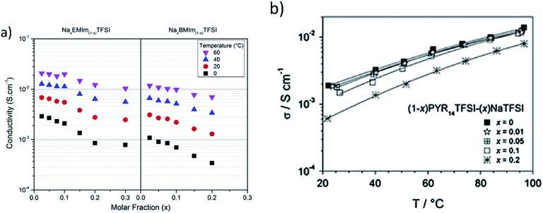 | ||
| Fig. 18 (a) Isotherms of the conductivity as a function of the molar fraction of Nax-EMIm(1−x)TFSI and NaxBMIm(1−x)TFSI (reproduced with permission153 © 2014, Elsevier) and (b) ionic conductivity vs. temperature for the (1 − x)PYR14TFSI–(x)NaTFSI electrolyte. Reproduced with permission154 © 2014, Elsevier. | ||
Chagas, et al.65 found that the use 10 mol% NaTFSI in PYR14TFSI provided higher reversibility of the de/sodiation process due to the increased electrochemical stability of the ionic liquid. The higher voltage (>4.2 V) P2–O2 phase transition of Na0.45Ni0.22Co0.11Mn0.66O2 in the Na‖Na0.45Ni0.22Co0.11Mn0.66O2 cell was able to occur because of the larger electrochemical potential voltage window. Another advantage of using IL based electrolytes is that the dissolution of Mn in the Na0.45Ni0.22Co0.11Mn0.66O2 cathode material did not occur at low voltages. The battery had high cycling stability and much higher discharge capacity compared to the same type of cell cycled in a PC based electrolyte.
The use of a proper electrolyte with specific active materials can improve the overall SIB system by enhancing ionic mobility and improving cyclability and retention. Ionic liquid based electrolytes with low salt concentration were optimal for ionic conductivity and overall performance of a tested SIB. IL based electrolytes do have an increased potential window which can be utilized for transition metal redox reactions that occur above the 4.0 V plateau. Plus, the use of this type of electrolyte makes it safe due to low flammability and volatility. Another safe electrolyte for use in the SIB is aqueous based, but low operating voltages may not be suitable for their practical application. The rapid capacity fading of the SIBs with aqueous electrolyte also needs to be improved before they can compete with SIBs which use organic or IL based electrolytes. Ponrouch, et al.150,152 found that mixtures of organic solvents gave higher conductivity and enhanced the overall performance of SIBs. These investigations27,30,150,152–154 reveal that the study of specific additives or materials for use in a SIB is critical in order to understand how they affect the overall performance of SIBs.
6. Binders/additives
There is not much research with respect to electrolyte additives for SIBs. Komaba, et al.23 recently tested several well-known Li ion battery additives in a SIB system and found that fluoroethylene carbonate (FEC) was efficient in improving the reversibility of sodium insertion in a Na aprotic cell with a hard carbon anode and NaNi0.5Mn0.5O2 based cathode. The addition of FEC improved capacity retention by suppressing decomposition of the propylene carbonate electrolyte solvent. FEC initially decomposed adding a voltage peak at 0.7 V during the first reduction. It is believed that this initial decomposition is critical in modifying the surface passivation layer, thereby increasing the electrochemical performance of the cell. In this same study, trans-difluoroethylene carbonate (DFEC), ethylene sulfate (ES), and vinyline carbonate (VC) were also tested as potential additives. It was found that DFEC had no beneficial effects, ES addition had a detrimental effect toward Na cells, and VC decreased reversible capacity of the cells.23In another study by Komaba, et al.,128 VC was added to PC in a 49![[thin space (1/6-em)]](https://www.rsc.org/images/entities/char_2009.gif) :
:![[thin space (1/6-em)]](https://www.rsc.org/images/entities/char_2009.gif) 1 volume ratio for beaker-type cells with hard carbon or NaNi0.5Mn0.5O2 as the working electrode and sodium foil as the quasi reference. Results show that it had a negative effect on Na insertion into the hard carbon anode. These findings led to the testing of the material in a coin type cell with the PC electrolyte and no additives. The initial efficiency of this cell reached 90%, which is believed to be due to the different cell configuration giving a more uniform current distribution.128
1 volume ratio for beaker-type cells with hard carbon or NaNi0.5Mn0.5O2 as the working electrode and sodium foil as the quasi reference. Results show that it had a negative effect on Na insertion into the hard carbon anode. These findings led to the testing of the material in a coin type cell with the PC electrolyte and no additives. The initial efficiency of this cell reached 90%, which is believed to be due to the different cell configuration giving a more uniform current distribution.128
A recent study by Dahbi, et al.155 found that the use of carboxymethyl cellulose binder (CMC) is superior when compared to commonly used PVDF for hard carbon negative electrodes in SIBs; and that the effectiveness of FEC was dependent upon its combination with such binders. A CR2032 coin cell was tested between 0 and 2.0 V vs. Na+/Na where Na metal was the counter electrode and the anode consisted of hard carbon in a 90![[thin space (1/6-em)]](https://www.rsc.org/images/entities/char_2009.gif) :
:![[thin space (1/6-em)]](https://www.rsc.org/images/entities/char_2009.gif) 10 ratio with CMC or PVDF. Based on their results, anodes with CMC without the use of the FEC additive in a 1 M NaPF6 PC electrolyte gave better cyclability by preventing electrolyte decomposition, and providing a preformed SEI layer on the hard carbon electrode. FEC with PVDF binder has a synergetic role in surface morphology and electrochemical behavior of hard carbon electrodes. FEC aided in forming a passivation layer on the hard carbon electrodes with PVDF and was necessary to improve cycle performance.155
10 ratio with CMC or PVDF. Based on their results, anodes with CMC without the use of the FEC additive in a 1 M NaPF6 PC electrolyte gave better cyclability by preventing electrolyte decomposition, and providing a preformed SEI layer on the hard carbon electrode. FEC with PVDF binder has a synergetic role in surface morphology and electrochemical behavior of hard carbon electrodes. FEC aided in forming a passivation layer on the hard carbon electrodes with PVDF and was necessary to improve cycle performance.155
Some studies pertaining to LIBs have found that the use of poly(vinylidene fluoride) (PVDF) is detrimental to the battery. Traditionally, this material is used to integrate electroactive particles; however, it has been found to accelerate the deterioration of cycling stability and cause irreversible capacity losses.148,156,157 The addition of this electrochemically inactive and insulating material impedes the performance of the active material because it can swell during cycling and reduce structural stability; thereby reducing cycle performance. The addition of these materials also leads to increased manufacturing costs which is of importance for EES. These findings are for LIBs but since the SIBs are similar in many ways, it is important to take these findings into consideration.
More studies related to binder addition and electrolyte additives are needed in order to determine optimal conditions for use of such materials in SIBs. A binder or additive that may be detrimental for LIBs has been found to be better for SIBs and vice versa, so it is imperative for the research community to understand how certain materials can inhibit or enhance the performance of SIBs.
7. Sodium ion transport
The insertion and removal of sodium was compared to those of lithium by Komaba, et al.128 in order to discuss the mechanism. Li insertion tends to occur between graphene layers and in hard carbon nanopores around the sloping and plateau regions of potentiograms between 0 and 1.2 V, and the sodium curve has a flat plateau at ∼0.1 V, as seen in Fig. 19.128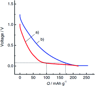 | ||
| Fig. 19 Chronopotentiograms of the second reduction for hard-carbon electrodes in (a) 1 mol dm−3 NaClO4 and (b) 1 mol dm−3 LiClO4 PC solution in Na and Li cells, respectively, at a rate of 25 mA g−1. Reproduced with permission128 © 2011, WILEY-VCH Verlag GmbH & Co. | ||
Sodium insertion into hard carbon was analyzed using XRD to determine the structural change that occurs around this voltage. A pristine electrode was first analyzed and then compared to a hard carbon electrode reduced at 0.2 V. The Bragg peak at 23.4° for the pristine electrode shifted to a lower angle at this reduced voltage, indicating that the spacing between graphene sheets expanded to accommodate sodium insertion in between the parallel layers. Upon oxidation to 2.0 V, the peak returned to its original position in the pristine condition, indicating the reversibility of the sodium. Small angle X-ray scattering (SAXS) and Raman spectroscopy data further confirm the structural change of the hard carbon due to reversible sodiation. For SAXS, the nanopores in hard carbon were assigned a scattering intensity of 0.03 to 0.07 Å when the electrode was electrochemically reduced from 0.2 V to 0 V.128 The intensity decreased reversibly attributing to reversible sodium ion insertion into the nanopores since the electron density contrast between the nanopores and carbon matrix decreased. Raman data showed that a shift occurred which signifies the elongation of the C–C bond (G-band) upon insertion during the low voltage sloping region, and upon approaching a voltage of zero, this G-band stays put, indicating there was no change in the state of the negatively charged graphene layers. The Na behaved as Li does with respect to Raman data when it is lithiated, but NMR and XPS studies need to be done in order to confirm if the Na forms quasimetallic nanoclusters in the nanopores of hard carbon, as Li does.128
Gotoh, et al.158 used solid state 23Na NMR to investigate sodium insertion into a hard carbon electrode of a SIB to confirm that quasi-metallic cluster formation does not occur. The state of sodium in the hard carbon was studied in comparison to Li intercalated carbon. Carbon was mixed in a 90![[thin space (1/6-em)]](https://www.rsc.org/images/entities/char_2009.gif) :
:![[thin space (1/6-em)]](https://www.rsc.org/images/entities/char_2009.gif) 10 weight ratio with PVDF to form the cathode and Na metal was used as the counter electrode in a coin type cell. 1 M NaClO4 in PC
10 weight ratio with PVDF to form the cathode and Na metal was used as the counter electrode in a coin type cell. 1 M NaClO4 in PC![[thin space (1/6-em)]](https://www.rsc.org/images/entities/char_2009.gif) :
:![[thin space (1/6-em)]](https://www.rsc.org/images/entities/char_2009.gif) FEC (98
FEC (98![[thin space (1/6-em)]](https://www.rsc.org/images/entities/char_2009.gif) :
:![[thin space (1/6-em)]](https://www.rsc.org/images/entities/char_2009.gif) 2 volume ratio) was used as the electrolyte. Galvanostatic testing at 0.5 mA cm−2 in a range of 2–0 V vs. Na/Na+ was used to cycle the batteries. Each battery was removed at a different charge level and studied with NMR. Samples with higher state of charge showed peaks at 5.2 and 9.9 ppm which correlate to reversible sodium stored between disordered graphene sheets in hard carbon. Peaks at −9 to −16 ppm were assigned to sodium in heterogeneously distributed closed nanopores in hard carbon. Though these results show sodium insertion during charging, the speed at which Na+ ions diffuse between different sites of hard carbon is slow in NMR time scale since it doesn't form quasi-metallic clusters in closed nanopores like Li at low temperatures.158
2 volume ratio) was used as the electrolyte. Galvanostatic testing at 0.5 mA cm−2 in a range of 2–0 V vs. Na/Na+ was used to cycle the batteries. Each battery was removed at a different charge level and studied with NMR. Samples with higher state of charge showed peaks at 5.2 and 9.9 ppm which correlate to reversible sodium stored between disordered graphene sheets in hard carbon. Peaks at −9 to −16 ppm were assigned to sodium in heterogeneously distributed closed nanopores in hard carbon. Though these results show sodium insertion during charging, the speed at which Na+ ions diffuse between different sites of hard carbon is slow in NMR time scale since it doesn't form quasi-metallic clusters in closed nanopores like Li at low temperatures.158
Deng, et al.27 studied the diffusion behavior of Na ions in Na2V6O16·nH2O and found that there was a linear relation between the CV peak current and the square root of the scan rate which indicated solid-state diffusion of Na ions in the host material during de/sodiation. Based on this, the diffusion coefficient of Na in Na2V6O16·nH2O in an aqueous battery was estimated using the Randles–Sevcik equation27
 | (1) |
Overall, the fundamentals of sodium ion transport have not attracted sufficient attention of the scientific community although this is an important area for charge–discharge kinetics and in some cases is critical for the cycle stability. The transport of Na ions during cycling is a pivotal parameter with respect to reversibility and retention. The cathode or anode material needs to have pathways to enable short, fast diffusion of Na ions during de/sodiation. Many groups have focused on creating unique structures for ion mobility with hope of obtaining optimal diffusion during cycling. They have been successful, but understanding exactly how ions diffuse in a specific structure, and the diffusion coefficient of the ion could aid in determining how to enhance or change a structure in the future to further improve the kinetics and cycle stability. Also, studying how the diffusion coefficient changes in the presence of different electrolytes would be beneficial in understanding how the salt and solvent affects diffusion of ions during cycling, but this type of study has not yet been undertaken.
8. SEI layer formation
The formation of the solid electrolyte interphase is a very critical aspect with respect to the performance of SIBs. The SEI layer forms in the first charge–discharge cycle due to electrolyte decomposition and is primarily the reason for initial capacity loss in the first cycle. This passivation layer then further protects the electrode by inhibiting side reactions of the electrolyte with the interfacial surface upon continued cycling. Since SEI layers consist of electrolyte decomposition products that are insoluble, the composition of the electrolyte has a strong impact on their properties such as ionic conduction, stability, and thickness.150 The SEI layer has many criteria, it should: (1) be electronically insulating to inhibit further reduction of the electrolyte, (2) reduce the reduction and oxidation kinetics to improve the electrolyte stability, and (3) allow transport of cations to be intercalated during cycling.128,150,152 The thermodynamic stability of organic solvents at ∼0 V vs. Na+/Na is not stable; therefore, passivation plays a key role in cycle performance of sodium insertion.128Komaba, et al.128 carried out a comparative investigation for passivating surfaces for hard-carbons in Na and Li cells. The morphology of hard carbons cycled in Li and Na cells was observed using SEM and confirmed sub-micrometer sized particles dispersed on the electrode surface. Na cells had larger unevenly distributed particles as compared to Li cells which had a uniform deposit layer. TEM analysis showed that the layers, whether uniform or not, were ∼30 nm in dry conditions.
X-ray photoelectron spectroscopy (XPS) measurements revealed the difference of the surface layers formed by the electrochemical cycling. The XPS spectra have a strong peak at 284.5 eV which is assigned to the sp2 carbon in C–C of graphene in hard carbon, while other peaks originate from the PVDF binder.128 The strongest peak almost disappears after cycling, indicating that the hard carbon in both cells was covered with the decomposition products of the electrolyte. Fig. 20 shows the XPS data.128
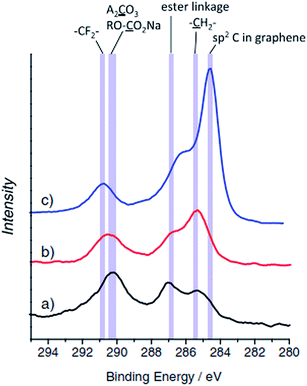 | ||
| Fig. 20 XPS carbon 1s spectra for the hard-carbon electrodes tested in (a) sodium and (b) lithium cells after the first cycle, and (c) pristine electrode. Reproduced with permission128 © 2011, WILEY-VCH Verlag GmbH & Co. | ||
The XPS data shows that the –CH2– peak intensity is stronger for the Li cell and corresponds to a larger amount of hydrocarbon compounds in its surface film. Another interesting characteristic is that the sp2 carbon became more clear and intense in the C 1s spectra which indicated that the surface layer in the Na cell is actually thinner than that in the Li cell.128 The further investigation of this passivation layer using time-of-flight secondary ion mass spectroscopy (TOF-SIMS) showed that the surface film in the Na cell was composed of inorganic compounds, whereas the passivation layer for Li cells was composed of organic compounds, as previously stated. Fig. 21 shows the TOF-SIMS results.128
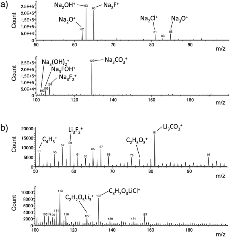 | ||
| Fig. 21 TOF-SIMS positive ion spectra for the hard-carbon electrodes after the first galvanostatic cycle in (a) sodium and (b) lithium cells. Reproduced with permission128 © 2011, WILEY-VCH Verlag GmbH & Co. | ||
These results show that the SEI layer allows for the reversible Na insertion of hard carbon. The SEI morphology and chemical composition differed for the Na and Li cases even though the same electrode and electrolyte material were used. The only difference was the intercalant alkali element. Further research is ongoing to determine the formation process and conductivity of the SEI layer for Na cells.128
Ponrouch et al.129 also investigated the SEI layer formation and found the same behavior for XPS results and confirmed that the SEI thickness is about the same as the XPS analysis depth (∼5–10 nm). The carbonaceous species that composed the SEI layer were very similar to those observed by Komaba, et al.152
9. Outlook and major challenges ahead
Significant and rapid progress of SIBs has been made in the last 5 years, as evidenced by the fact that 80% of the publications reviewed in this article are published in the last 5 years. The speedy advancement in SIBs can be attributed to the similarity between LIBs and SIBs in their operating principles22 which greatly shortens the learning curve and expedites the progress of SIBs. In fact, the progress made in SIBs is so large that the properties of SIBs can now compete with that of LIBs in some application areas. Tables 2 and 3 summarize the specific capacities and numbers of cycles that have been achieved experimentally for the most promising cathodes and anodes of the SIBs investigated so far, respectively. Based on these experimentally accomplished values, the potentials of SIBs in competing against LIBs in three critical application arenas, portable electronic devices, electrical grid and electric vehicles, can be offered below.| Material | Specific capacity [mA h g−1] | Charge–discharge cycles demonstrated | Ref. |
|---|---|---|---|
| a Na+ insertion.b K+ insertion.c With an aqueous electrolyte. | |||
| Na0.44MnO2 | 120 | 1000 | 29 |
| α-Fe2O3/C nanotubes | 99 | 500 | 59 |
| Na3V2(PO4)3/C | 30 | 30![[thin space (1/6-em)]](https://www.rsc.org/images/entities/char_2009.gif) 000 000 |
81 |
| Na3V2(PO4)3/graphene | 90 | 300 | 88 |
| Na1.5VPO4.8F0.7 | 130 | 500 | 94 |
| Na0.45Ni0.22Co0.11Mn0.66O2 | 135 | 250 | 61 |
| Na2MnFe(CN)6 | 145 | 1200 | 161 |
| K0.6Ni1.2Fe(CN)6·3.6H2O | 52 | 5000a/1000b | 26c |
| NaxFeyMn1−yO2 | 190 | 30–40 | 60 and 71 |
Portable electronic devices such as cell phones, laptop computers, iPod and MP3 player are currently powered by LIBs capable of at least 200–300 cycles with retention of 80% of their capacity.159 LiCoO2 with a specific capacity of 155 mA h g−1 is most widely used as the cathode in commercial LIBs and, when coupled with the graphite anode (350 mA h g−1), provides a cell voltage of 3.8 V and a specific energy of 408 W h kg−1 (based on the electrode materials only).160 Such a specific energy and the required cycle life (200 cycles or more) are gradually approached by SIBs. For example, one may pair a Na1.5VPO4.8F0.7 cathode94 with a carbon nanostructure anode131 to make a SIB with a 210-cycle life and a specific energy of 299 W h kg−1 at the beginning of the battery life and 284 W h kg−1 at the end of 210-cycle life, based on the data listed in Table 2 and the cell voltage of 3.3 V (with the Na1.5VPO4.8F0.7 cathode at the average potential of 3.8 V vs. Na/Na+ and the carbon nanostructure anode at the average potential of 0.5 V vs. Na/Na+).94,131 NaxFeyMn1−yO2 would also be a great material to compete with LIBS due to its estimated energy density of 520 W h kg−1 based on an average operating voltage of 2.75 vs. Na/Na+,60,71 but needs to be able to cycle longer in order to replace the LIB in the future with respect to the required cycle life. With the additional improvements of SIB electrodes in the near future and the significant cost advantage of SIBs over LIBs based on the raw material prices and the use of Al current collectors (Table 1), it is safe to conclude that SIBs will be strong contenders with LIBs in the areas of portable electronic devices and power tools in the next several years.
In the area of grid-scale electrical energy storage for renewable energy integration, frequency regulation, peak shaving and voltage regulation, the volumetric and gravimetric energy densities of batteries are not critical. In contrast, ultra long cycle life (>20![[thin space (1/6-em)]](https://www.rsc.org/images/entities/char_2009.gif) 000 cycles and calendar life of 15 to 20 years), high round trip efficiency (>90%), low cost and sufficient power capability are the major requirements. In light of these requirements, SIBs would be advantageous over LIBs because Na is highly abundant, low cost, and environmentally friendly. In this context, the porous Na3V2(PO4)3/C cathode81 has already been demonstrated to be capable of 30
000 cycles and calendar life of 15 to 20 years), high round trip efficiency (>90%), low cost and sufficient power capability are the major requirements. In light of these requirements, SIBs would be advantageous over LIBs because Na is highly abundant, low cost, and environmentally friendly. In this context, the porous Na3V2(PO4)3/C cathode81 has already been demonstrated to be capable of 30![[thin space (1/6-em)]](https://www.rsc.org/images/entities/char_2009.gif) 000 cycles (Table 2). The Prussian blue analogue Na2MnFe(CN)6 has been tested 1200 cycles and projected to be capable of 10
000 cycles (Table 2). The Prussian blue analogue Na2MnFe(CN)6 has been tested 1200 cycles and projected to be capable of 10![[thin space (1/6-em)]](https://www.rsc.org/images/entities/char_2009.gif) 000 cycles with 95% capacity retention.161 Therefore, there exist good SIB cathode materials for ultra long cycle life. The progress made in SIB anodes with ultra long cycle life is also very impressive with 3000 and 5000 cycles being demonstrated using Na2/3Co1/3Ti2/3O2 and Na2Ti6O13, respectively146,147 (Table 3). Nevertheless, continued research in increasing the cycle life of SIB anodes and cathodes would be an important research topic in the near future to make SIBs a viable technology for grid-scale energy storage. Saravanan, et al.81 have predicted that the commercial lead acid batteries currently used in the electric grid would become obsolete if a suitable anode with a stable capacity of ∼120 mA h g−1 is developed and paired with the Na3V2(PO4)3/C cathode since its energy density would be 10 times greater.
000 cycles with 95% capacity retention.161 Therefore, there exist good SIB cathode materials for ultra long cycle life. The progress made in SIB anodes with ultra long cycle life is also very impressive with 3000 and 5000 cycles being demonstrated using Na2/3Co1/3Ti2/3O2 and Na2Ti6O13, respectively146,147 (Table 3). Nevertheless, continued research in increasing the cycle life of SIB anodes and cathodes would be an important research topic in the near future to make SIBs a viable technology for grid-scale energy storage. Saravanan, et al.81 have predicted that the commercial lead acid batteries currently used in the electric grid would become obsolete if a suitable anode with a stable capacity of ∼120 mA h g−1 is developed and paired with the Na3V2(PO4)3/C cathode since its energy density would be 10 times greater.
In the area of electric vehicles, the high volumetric and gravimetric densities of batteries are critical. Good cycle life (>1000 cycles) is also essential. As mentioned before, based on Na atomic weight and ionic diameter, the energy densities of SIBs will always be lower than that of LIBs. In spite of these constraints, significant progress has been made with cathodes reaching the specific capacity of 145 mA h g−1 after 1200 cycles and anodes reaching the specific capacity of 400 mA h g−1 after 150 cycles (Tables 2 and 3). However, further improvements in the energy density are needed and the breakthrough will likely be from developing electrodes with higher operating voltages or electrodes with more than one Na ion insertion or reaction per formula unit. The drawback of the former approach is that the redox reactions that occur at higher voltages than the potential window offered by current electrolytes can be detrimental to the cycle stability of batteries. To harvest the high voltage benefit of this type of electrode, electrolytes that can withstand high voltages need to be developed. IL-based electrolytes can offer the potential window that is needed for high voltage electrodes, but such electrolytes are relatively new and need to be tested further. In addition, the cost of IL-based electrolytes needs to be reduced drastically for broad market penetration.
Developing electrodes with more than one Na ion insertion or reaction per formula unit could hold great promise in increasing the energy density of SIBs. The issues associated with alloy- and compound formation-type electrodes (e.g., Sn, Si, Sb and P) are often low cycle stability due to significant volume changes during charge–discharge. For example, P has a high capacity but with 491% volume expansion when forming Na3P during sodiation.162,163 Such large volume expansion and shrinkage during cycling result in particle pulverization, loss of electrical contact, and unstable SEI. The key to solving this problem is to confine the volume change within a sub-micrometer shell via “core–shell” structures. Such a strategy has been successfully devised to develop the double-walled Si nanotube anode capable of 6000 cycles for LIBs.164 The superior cycle stability of the double-walled Si nanotube anode is due to the hollow tube structure which has an inner Si tube covered by an outer SiOx shell. The inner hollow Si tube has a free surface to allow silicon to expand inward during lithiation and shrink back to its original position during delithiation, whereas the outer SiOx shell prevents silicon from expanding outwards during lithiation and permits the formation of a stable SEI on its surface.164 Similar strategies can be utilized for high capacity electrodes with large volume changes for SIBs.
Some efforts have been made in developing electrodes with more than one Na ion insertion per formula unit. These materials such as Na3V2(PO4)3,81,86–88 Na1.5VPO4.8F0.7,94 Na3MnCO3PO4,106 Na4Co3(PO4)2P2O7,107 Na2MnFe(CN)6,114,161 and Na2Ti3O7![[thin space (1/6-em)]](https://www.rsc.org/images/entities/char_2009.gif) 142 do exhibit relatively high specific capacities, and in some cases higher than 150 mA h g−1.106,142 However, further improvements are needed since few offer specific capacities higher than 200 mA h g−1 with long cycle life. Future experimental efforts guided by first principles calculations22,102,165 are expected to accelerate research in this direction to develop electrodes with high specific capacities and superior cycle stability.
142 do exhibit relatively high specific capacities, and in some cases higher than 150 mA h g−1.106,142 However, further improvements are needed since few offer specific capacities higher than 200 mA h g−1 with long cycle life. Future experimental efforts guided by first principles calculations22,102,165 are expected to accelerate research in this direction to develop electrodes with high specific capacities and superior cycle stability.
10. Conclusion
The abundance and low cost of sodium has made it a promising alternative to lithium for an ion battery system. Research has shown that there are many Na chemistries that are suitable for SIBs. Some Na based materials with similar structure to that of Li analogues have been found to be electrochemically active where the latter have not, which makes the research of Na based electrodes an exciting endeavor. The larger atomic weight and ionic radius of Na compared to Li generates the need for specialized structures that can facilitate strain and offer short diffusion paths for ion transport during cycling. Further research needs to be done for electrode materials of SIBs in order to determine the right structures and configuration for an optimized cell. Another key element to optimize the SIB is electrolyte investigation and selection. The effect of an electrolyte and additives on SEI layer formation and ion transport can be detrimental if not chosen correctly for specific anodic and cathodic materials. Electrolytes that are stable and do not continually decompose with cycling are preferred, and the use of additives with low salt concentration can offer these properties. Ionic liquid based electrolytes are beginning to be researched and are promising for higher voltage SIBs for transition metal redox at higher potentials, but it is still a new concept and needs continued research for effective utilization in SIBs. Overall, the outlook for the use of SIBs in current technology is favorable as long as cost, safety, cyclic stability, and energy density guidelines are met.References
- J. Liu, J. G. Zhang, Z. Yang, J. P. Lemmon, C. Imhoff, G. L. Graff, L. Li, J. Hu, C. Wang, J. Xiao, G. Xia, V. V. Viswanathan, S. Baskaran, V. Sprenkle, X. Li, Y. Shao and B. Schwenzer, Adv. Funct. Mater., 2013, 23, 929 CrossRef CAS PubMed.
- M. D. Slater, D. Kim, E. Lee and C. S. Johnson, Adv. Funct. Mater., 2013, 23, 947 CrossRef CAS PubMed.
- V. Palomares, P. Serras, I. Villaluenga, K. B. Hueso, J. Carretero-González and T. Rojo, Energy Environ. Sci., 2012, 5, 5884 CAS.
- H. Pan, Y. S. Hu and L. Chen, Energy Environ. Sci., 2013, 6, 2338 CAS.
- Research Center for Energy Economics, http://www.ffe.de/en/the-topics/resources-and-climate-protection/6-range-assessment-of-current-lithium-reserves, accessed June 2013.
- N. Yabuuchi, K. Kubota, M. Dahbi and S. Komaba, Chem. Rev., 2014, 114, 11636 CrossRef CAS PubMed.
- S. W. Kim, D. H. Seo, X. Ma, G. Ceder and K. Kang, Adv. Energy Mater., 2012, 2, 710 CrossRef CAS PubMed.
- Elemental abundances, http://commons.wikimedia.org/wiki/File:Elemental_abundances.svg, accessed January 2013.
- B. L. Ellis and L. F. Nazar, Curr. Opin. Solid State Mater. Sci., 2012, 16, 168 CrossRef CAS PubMed.
- V. Palomares, M. Casas-Cabanas, E. Castillo-Martínez, M. H. Han and T. Rojo, Energy Environ. Sci., 2013, 6, 2312 CAS.
- M. H. Han, E. Gonzalo, G. Singh and T. Rojo, Energy Environ. Sci., 2015, 8, 81 CAS.
- K. Mizushima, P. C. Jones, P. J. Wiseman and J. B. Goodenough, Mater. Res. Bull., 1980, 15, 783 CrossRef CAS.
- A. S. Nagelberg and W. L. Worrell, J. Solid State Chem., 1979, 29, 345 CrossRef CAS.
- J. P. Parant, R. Olazcuaga, M. Devalette, C. Fouassier and P. Hagenmuller, J. Solid State Chem., 1971, 3, 1 CrossRef CAS.
- C. Delmas, C. Fouassier and P. Hagenmuller, Physica B+C, 1980, 99, 81 CrossRef CAS.
- C. Delmas, J. Braconnier, C. Fouassier and P. Hagenmuller, Solid State Ionics, 1981, 3–4, 165 CrossRef CAS.
- J. J. Braconnier, C. Delmas and P. Hagenmuller, Mater. Res. Bull., 1982, 17, 993 CrossRef CAS.
- J. J. Braconnier, C. Delmas, C. Fouassier and P. Hagenmuller, Mater. Res. Bull., 1980, 15, 1797 CrossRef CAS.
- M. S. Whittingham, Science, 1976, 192, 1126 CAS.
- M. S. Whittingham, J. Chem. Phys., 1971, 54, 414 CrossRef CAS PubMed.
- M. S. Whittingham, J. Chem. Soc., Chem. Commun., 1974, 328 RSC.
- S. P. Ong, V. L. Chevrier, G. Hautier, A. Jain, C. Moore, S. Kim, X. Ma and G. Ceder, Energy Environ. Sci., 2011, 4, 3680 CAS.
- S. Komaba, T. Ishikawa, N. Yabuuchi, W. Murata, A. Ito and Y. Ohsawa, ACS Appl. Mater. Interfaces, 2011, 3, 4165 CAS.
- J. F. Whitacre, T. Wiley, S. Shanbhag, Y. Wenzhuo, A. Mohamed, S. E. Chun, E. Weber, D. Blackwood, E. Lynch-Bell, J. Gulakowski, C. Smith and D. Humphreys, J. Power Sources, 2012, 213, 255 CrossRef CAS PubMed.
- H. Qin, Z. P. Song, H. Zhan and Y. H. Zhou, J. Power Sources, 2014, 249, 367 CrossRef CAS PubMed.
- C. D. Wessells, S. V. Peddada, R. A. Huggins and Y. Cui, Nano Lett., 2011, 11, 5421 CrossRef CAS PubMed.
- C. Deng, S. Zhang, Z. Dong and Y. Shang, Nano Energy, 2014, 4, 49 CrossRef CAS PubMed.
- J. F. Whitacre, A. Tevar and S. Sharma, Electrochem. Commun., 2010, 12, 463 CrossRef CAS PubMed.
- Y. Cao, L. Xiao, W. Wang, D. Choi, Z. Nie, J. Yu, L. V. Saraf, Z. Yang and J. Liu, Adv. Mater., 2011, 23, 3155 CrossRef CAS PubMed.
- W. Song, X. Ji, Y. Zhu, H. Zhu, F. Li, J. Chen, F. Lu, Y. Yao and C. E. Banks, ChemElectroChem, 2014, 1, 871 CrossRef CAS PubMed.
- D. J. Kim, R. Ponraj, A. G. Kannan, H. Lee, R. Fathi, R. Ruffo, C. M. Mari and D. Kyung, J. Power Sources, 2013, 244, 758 CrossRef CAS PubMed.
- Y. Liu, Y. Qiao, W. Zhang, H. Xu, Z. Li, Y. Shen, L. Yuan, X. Hu, X. Dai and Y. Huang, Nano Energy, 2014, 5, 97 CrossRef CAS PubMed.
- Z. Li, D. Young, K. Xiang, W. C. Carter and Y.-M. Chiang, Adv. Energy Mater., 2013, 3, 290 CrossRef CAS PubMed.
- K. Kubota, N. Yabuuchi, H. Yoshida, M. Dahbi and S. Komaba, MRS Bull., 2014, 39, 416 CrossRef CAS.
- H. Kim, D. J. Kim, D. Seo, M. S. Yeom, K. Kang, D. K. Kim and Y. Jung, Chem. Mater., 2012, 24, 1205 CrossRef CAS.
- X. Ma, H. Chen and G. Ceder, J. Electrochem. Soc., 2011, 158, A1307 CrossRef CAS PubMed.
- I. H. Jo, H. S. Ryu, D. G. Gu, J. S. Park, I. S. Ahn, H. J. Ahn, T. H. Nam and K. W. Kim, Mater. Res. Bull., 2014, 3, 2 Search PubMed.
- N. Yabuuchi, K. Yoshii, S. Myung, I. Nakai and S. Komaba, J. Am. Chem. Soc., 2011, 133, 4404 CrossRef CAS PubMed.
- S. Yang, X. Wang, Y. Wang, Q. Chen, J. Li and X. Yang, Trans. Nonferrous Met. Soc. China, 2010, 20, 1892 CrossRef CAS.
- A. Mendiboure, C. Delmas and P. Hagenmuller, J. Solid State Chem., 1985, 57, 323 CrossRef CAS.
- J. Zhao, H. Chen, J. Shi, J. Gu, X. Dong, J. Gao, M. Ruan and L. Yu, Microporous Mesoporous Mater., 2008, 116, 432 CrossRef CAS PubMed.
- J. P. Parant, R. Olazcuaga, M. Devalette, C. Fouassier and P. Hagenmuller, J. Solid State Chem., 1971, 3, 1 CrossRef CAS.
- O. A. Vargas, A. Caballero, L. Hernán and J. Morales, J. Power Sources, 2011, 196, 3350 CrossRef CAS PubMed.
- N. Bucher, S. Hartung, A. Nagasubramanian, Y. L. Cheah, H. E. Hoster and S. Madhavi, ACS Appl. Mater. Interfaces, 2014, 6, 8059 CAS.
- A. Caballero, L. Hernán, J. Morales, L. Sánchez and J. Santos, J. Solid State Chem., 2003, 174, 365 CrossRef CAS.
- F. Sauvage, L. Laffont, J. M. Tarascon and E. Baudrin, Inorg. Chem., 2007, 46, 3289 CrossRef CAS PubMed.
- J. Billaud, R. J. Clement, A. R. Armstrong, J. Canales-Vazquez, P. Rozier, C. P. Grey and P. G. Bruce, J. Am. Chem. Soc., 2014, 136, 17243 CrossRef CAS PubMed.
- S. Komaba, C. Takei, T. Nakayama, A. Ogata and N. Yabuuchi, Electrochem. Commun., 2010, 12, 355 CrossRef CAS PubMed.
- C. Y. Chen, K. Matsumoto, T. Nohira, R. Hagiwara, A. Fukunaga, S. Sakai, K. Nitta and S. Inazawa, J. Power Sources, 2013, 237, 52 CrossRef CAS PubMed.
- J. J. Ding, Y.-N. Zhou, Q. Sun and Z.-W. Fu, Electrochem. Commun., 2012, 22, 85 CrossRef CAS PubMed.
- X. Xia and J. R. Dahn, Electrochem. Solid-State Lett., 2012, 15, A1 CrossRef CAS PubMed.
- S. Komaba, T. Nakayama, A. Ogata, T. Shimizu, C. Takei, S. Takada, A. Hokura and I. Nakai, ECS Trans., 2009, 16, 43 CAS.
- Y. Takeda, K. Nakahara, M. Nishijima, N. Imanishi, O. Yamamoto, M. Takano and R. Kanno, Mater. Res. Bull., 1994, 29, 659 CrossRef CAS.
- M. Tabuchi, Solid State Ionics, 1996, 90, 129 CrossRef CAS.
- M. C. Blesa, E. Moran, C. León, J. Santamaria, J. D. Tornero and N. Menéndez, Solid State Ionics, 1999, 126, 81 CrossRef CAS.
- J. Zhao, L. Zhao, N. Dimov, S. Okada and T. Nishida, J. Electrochem. Soc., 2013, 160, A3077 CrossRef CAS PubMed.
- H. Yoshida, N. Yabuuchi and S. Komaba, in ECS Meet. Abstr. MA2012-02, 2011, vol. 201, p. 1850.
- E. Monyoncho and R. Bissessur, Mater. Res. Bull., 2013, 48, 2678 CrossRef CAS PubMed.
- B. Koo, S. Chattopadhyay, T. Shibata, V. B. Prakapenka, C. S. Johnson, T. Rajh and E. V. Shevchenko, Chem. Mater., 2013, 25, 245 CrossRef CAS.
- N. Yabuuchi, M. Kajiyama, J. Iwatate, H. Nishikawa, S. Hitomi, R. Okuyama, R. Usui, Y. Yamada and S. Komaba, Nat. Mater., 2012, 11, 512 CrossRef CAS PubMed.
- D. Buchholz, A. Moretti, R. Kloepsch, S. Nowak, V. Siozios, M. Winter and S. Passerini, Chem. Mater., 2013, 25, 142 CrossRef CAS.
- S. M. Oh, S. T. Myung, C. S. Yoon, J. Lu, J. Hassoun, B. Scrosati, K. Amine and Y. K. Sun, Nano Lett., 2014, 14, 1620 CrossRef CAS PubMed.
- S. Doubaji, M. Valvo, I. Saadoune, M. Dahbi and K. Edström, J. Power Sources, 2014, 266, 275 CrossRef CAS PubMed.
- J. Xu, S. L. Chou, J. L. Wang, H. K. Liu and S. X. Dou, ChemElectroChem, 2014, 1, 371 CrossRef CAS PubMed.
- L. G. Chagas, D. Buchholz, L. Wu, B. Vortmann and S. Passerini, J. Power Sources, 2014, 247, 377 CrossRef CAS PubMed.
- H. Yu, S. Guo, Y. Zhu, M. Ishida and H. Zhou, Chem. Commun., 2014, 50, 457 RSC.
- D. Yuan, X. Hu, J. Qian, F. Pei, F. Wu, R. Mao, X. Ai, H. Yang and Y. Cao, Electrochim. Acta, 2014, 116, 300 CrossRef CAS PubMed.
- J. S. Thorne, R. A. Dunlap and M. N. Obrovac, J. Electrochem. Soc., 2012, 160, A361 CrossRef PubMed.
- B. Mortemard de Boisse, D. Carlier, M. Guignard and C. Delmas, J. Electrochem. Soc., 2013, 160, A569 CrossRef CAS PubMed.
- N. Yabuuchi and S. Komaba, Sci. Technol. Adv. Mater., 2014, 15, 043501 CrossRef.
- J. Zhao, J. Xu, D. H. Lee, N. Dimov, Y. S. Meng and S. Okada, J. Power Sources, 2014, 264, 235 CrossRef CAS PubMed.
- J. Billaud, G. Singh, A. R. Armstrong, E. Gonzalo, V. Roddatis, M. Armand, T. Rojo and P. G. Bruce, Energy Environ. Sci., 2014, 7, 1387 CAS.
- J. Wang, J. Yang, Y. Nuli and R. Holze, Electrochem. Commun., 2007, 9, 31 CrossRef CAS PubMed.
- T. H. Hwang, D. S. Jung, J. S. Kim, B. G. Kim and J. W. Choi, Nano Lett., 2013, 13, 4532 CrossRef CAS PubMed.
- J. S. Kim, D. Y. Kim, G. B. Cho, T. H. Nam, K. W. Kim, H. S. Ryu, J. H. Ahn and H. J. Ahn, J. Power Sources, 2009, 189, 864 CrossRef CAS PubMed.
- T. B. Kim, W. H. Jung, H. S. Ryu, K. W. Kim, J. H. Ahn, K. K. Cho, G. B. Cho, T. H. Nam, I. S. Ahn and H. J. Ahn, J. Alloys Compd., 2008, 449, 304 CrossRef CAS PubMed.
- J. S. Kim, G. B. Cho, K. W. Kim, J. H. Ahn, G. Wang and H. J. Ahn, Curr. Appl. Phys., 2011, 11, S215 CrossRef PubMed.
- J. S. Kim, H. J. Ahn, H. S. Ryu, D. J. Kim, G. B. Cho, K. W. Kim, T. H. Nam and J. H. Ahn, J. Power Sources, 2008, 178, 852 CrossRef CAS PubMed.
- P. Barpanda, J. N. Chotard, N. Recham, C. Delacourt, M. Ati, L. Dupont, M. Armand and J. M. Tarascon, Inorg. Chem., 2010, 49, 7401 CrossRef CAS PubMed.
- P. Barpanda, G. Oyama, S. I. Nishimura, S. C. Chung and A. Yamada, Nat. Commun., 2014, 5, 1 Search PubMed.
- K. Saravanan, C. W. Mason, A. Rudola, K. H. Wong and P. Balaya, Adv. Energy Mater., 2013, 3, 444 CrossRef CAS PubMed.
- C. Zhu, K. Song, P. A. Van Aken, J. Maier and Y. Yu, Nano Lett., 2014, 14, 2175 CrossRef CAS PubMed.
- L. S. Plashnitsa, E. Kobayashi, Y. Noguchi, S. Okada and J. Yamaki, J. Electrochem. Soc., 2010, 157, A536 CrossRef CAS PubMed.
- Y. Uebou, T. Kiyabu, S. Okada and J. Ichi Yamaki, Rep. Inst. Adv. Mater. Study, Kyushu Univ., 2002, 16, 1 CAS.
- S. Y. Lim, H. Kim, R. A. Shakoor, Y. Jung and J. W. Choi, J. Electrochem. Soc., 2012, 159, A1393 CrossRef CAS PubMed.
- Z. Jian, L. Zhao, H. Pan, Y. S. Hu, H. Li, W. Chen and L. Chen, Electrochem. Commun., 2012, 14, 86 CrossRef CAS PubMed.
- Z. Jian, W. Han, X. Lu, H. Yang, Y. S. Hu, J. Zhou, Z. Zhou, J. Li, W. Chen, D. Chen and L. Chen, Adv. Energy Mater., 2013, 3, 156 CrossRef CAS PubMed.
- Y. H. Jung, C. H. Lim and D. K. Kim, J. Mater. Chem. A, 2013, 1, 11350 CAS.
- Q. Sun, Q. Q. Ren and Z. W. Fu, Electrochem. Commun., 2012, 23, 145 CrossRef CAS PubMed.
- J. Kang, S. Baek, V. Mathew, J. Gim, J. Song, H. Park, E. Chae, A. K. Rai and J. Kim, J. Mater. Chem., 2012, 22, 20857 RSC.
- Y. Kawabe, N. Yabuuchi, M. Kajiyama, N. Fukuhara, T. Inamasu, R. Okuyama, I. Nakai and S. Komaba, Electrochem. Commun., 2011, 13, 1225 CrossRef CAS PubMed.
- Y. Lu, S. Zhang, Y. Li, L. Xue, G. Xu and X. Zhang, J. Power Sources, 2014, 247, 770 CrossRef CAS PubMed.
- C. Vidal-Abarca, P. Lavela, J. L. Tirado, A. V. Chadwick, M. Alfredsson and E. Kelder, J. Power Sources, 2012, 197, 314 CrossRef CAS PubMed.
- Y. U. Park, D. H. Seo, H. S. Kwon, B. Kim, J. Kim, H. Kim, I. Kim, H. I. Yoo and K. Kang, J. Am. Chem. Soc., 2013, 135, 13870 CrossRef CAS PubMed.
- R. K. B. Gover, A. Bryan, P. Burns and J. Barker, Solid State Ionics, 2006, 177, 1495 CrossRef CAS PubMed.
- J. Barker, M. Y. Saidi and J. L. Swoyer, Electrochem. Solid-State Lett., 2003, 6, A1 CrossRef CAS PubMed.
- N. Recham, J. N. Chotard, L. Dupont, K. Djellab, M. Armand and J. M. Tarascon, J. Electrochem. Soc., 2009, 156, A993 CrossRef CAS PubMed.
- H. Zhuo, X. Wang, A. Tang, Z. Liu, S. Gamboa and P. J. Sebastian, J. Power Sources, 2006, 160, 698 CrossRef CAS PubMed.
- P. Serras, V. Palomares, P. Kubiak, L. Lezama and T. Rojo, Electrochem. Commun., 2013, 34, 344 CrossRef CAS PubMed.
- M. Xu, P. Xiao, S. Stauffer, J. Song, G. Henkelman and J. B. Goodenough, Chem. Mater., 2014, 26, 3089 CrossRef CAS.
- N. Sharma, P. Serras, V. Palomares, H. E. A. Brand, J. Alonso, P. Kubiak, M. L. Fdez-Gubieda and T. Rojo, Chem. Mater., 2014, 26, 3391 CrossRef CAS.
- G. Hautier, A. Jain, H. Chen, C. Moore, S. P. Ong and G. Ceder, J. Mater. Chem., 2011, 21, 17147 RSC.
- H. Chen, G. Hautier, A. Jain, C. Moore, B. Kang, R. Doe, L. Wu, Y. Zhu, Y. Tang and G. Ceder, Chem. Mater., 2012, 24, 2009 CrossRef CAS.
- H. Chen, G. Hautier and G. Ceder, J. Am. Chem. Soc., 2012, 134, 19619 CrossRef CAS PubMed.
- H. Chen, Q. Hao, O. Zivkovic, G. Hautier, L. Du, Y. Tang, Y. Hu, X. Ma, C. P. Grey and G. Ceder, Chem. Mater., 2013, 25, 2777 CrossRef CAS.
- C. Wang, M. Sawicki, S. Emani, C. Liu and L. Shaw, Electrochim. Acta, 2015, 161, 322 CrossRef CAS PubMed.
- M. Nose, H. Nakayama, K. Nobuhara, H. Yamaguchi, S. Nakanishi and H. Iba, J. Power Sources, 2013, 234, 175 CrossRef CAS PubMed.
- S. Y. Lim, H. Kim, J. Chung, J. H. Lee, B. G. Kim, J. J. Choi, K. Y. Chung, W. Cho, S. J. Kim, W. A. Goddard, Y. Jung and J. W. Choi, Proc. Natl. Acad. Sci. U. S. A., 2014, 111, 599 CrossRef CAS PubMed.
- I. D. Gocheva, M. Nishijima, T. Doi, S. Okada, J. Yamaki and T. Nishida, J. Power Sources, 2009, 187, 247 CrossRef CAS PubMed.
- N. Dimov, A. Nishimura, K. Chihara, A. Kitajou, I. D. Gocheva and S. Okada, Electrochim. Acta, 2013, 110, 214 CrossRef CAS PubMed.
- Y. Yamada, T. Doi, I. Tanaka, S. Okada and J. Yamaki, J. Power Sources, 2011, 196, 4837 CrossRef CAS PubMed.
- A. Kitajou, H. Komatsu, K. Chihara, I. D. Gocheva, S. Okada and J. Yamaki, J. Power Sources, 2012, 198, 389 CrossRef CAS PubMed.
- A. Eftekhari, J. Power Sources, 2004, 126, 221 CrossRef CAS PubMed.
- L. Wang, Y. Lu, J. Liu, M. Xu, J. Cheng, D. Zhang and J. B. Goodenough, Angew. Chem., Int. Ed., 2013, 52, 1964 CrossRef CAS PubMed.
- C. D. Wessells, S. V. Peddada, M. T. McDowell, R. A. Huggins and Y. Cui, J. Electrochem. Soc., 2012, 159, A98 CrossRef CAS PubMed.
- C. D. Wessells, R. A. Huggins and Y. Cui, Nat. Commun., 2011, 2, 550 CrossRef PubMed.
- Y. Lu, L. Wang, J. Cheng and J. B. Goodenough, Chem. Commun., 2012, 48, 6544 RSC.
- Y. Yue, A. J. Binder, B. Guo, Z. Zhang, Z. A. Qiao, C. Tian and S. Dai, Angew. Chem., 2014, 126, 3198 CrossRef PubMed.
- R. Alcántara, J. M. Jimeénez Mateos and J. L. Tirado, J. Electrochem. Soc., 2002, 149, A201 CrossRef PubMed.
- M. M. Doeff, Y. Ma, S. J. Visco and L. C. De Jonghe, J. Electrochem. Soc., 1993, 140, 169 CrossRef PubMed.
- E. Zhecheva, R. Stoyanova, J. M. Jimenez-Mateos, R. Alcántara, P. Lavela and J. L. Tirado, Carbon, 2002, 40, 2301 CrossRef CAS.
- R. Alcántara, P. Lavela, G. F. Ortiz and J. L. Tirado, Electrochem. Solid-State Lett., 2005, 8, A222 CrossRef PubMed.
- R. Alcántara, J. M. Jimenez-Mateos, P. Lavela and J. L. T. Tirado, Electrochem. Commun., 2001, 3, 639 CrossRef.
- P. Thomas, J. Ghanbaja, D. Billaud, H. Poincare and I. Nancy, Electrochim. Acta, 1999, 45, 423 CrossRef CAS.
- Z. Wang, L. Qie, L. Yuan, W. Zhang, X. Hu and Y. Huang, Carbon, 2013, 55, 328 CrossRef CAS PubMed.
- L. Fu, K. Tang, K. Song, P. A. van Aken, Y. Yu and J. Maier, Nanoscale, 2014, 6, 1384 RSC.
- D. A. Stevens and J. R. Dahn, J. Electrochem. Soc., 2001, 148, A803 CrossRef CAS PubMed.
- S. Komaba, W. Murata, T. Ishikawa, N. Yabuuchi, T. Ozeki, T. Nakayama, A. Ogata, K. Gotoh and K. Fujiwara, Adv. Funct. Mater., 2011, 21, 3859 CrossRef CAS PubMed.
- A. Ponrouch, A. R. Goñi and M. R. Palacín, Electrochem. Commun., 2013, 27, 85 CrossRef CAS PubMed.
- J. Zhao, L. Zhao, K. Chihara, S. Okada, J. Yamaki, S. Matsumoto, S. Kuze and K. Nakane, J. Power Sources, 2013, 244, 752 CrossRef CAS PubMed.
- J. Ding, H. Wang, Z. Li, A. Kohandehghan, K. Cui, Z. Xu, B. Zahiri, X. Tan, E. M. Lotfabad, B. C. Olsen and D. Mitlin, ACS Nano, 2013, 7, 11004 CrossRef CAS PubMed.
- Y. Cao, L. Xiao, M. L. Sushko, W. Wang, B. Schwenzer, J. Xiao, Z. Nie, L. V. Saraf, Z. Yang and J. Liu, Nano Lett., 2012, 12, 3783 CrossRef CAS PubMed.
- Y. Liu, Y. Xu, Y. Zhu, J. N. Culver, C. A. Lundgren, K. Xu and C. Wang, ACS Nano, 2013, 7, 3627 CrossRef CAS PubMed.
- J. Qian, X. Wu, Y. Cao, X. Ai and H. Yang, Angew. Chem., Int. Ed., 2013, 52, 4633 CrossRef CAS PubMed.
- K. Dai, H. Zhao, Z. Wang, X. Song, V. Battaglia and G. Liu, J. Power Sources, 2014, 263, 276 CrossRef CAS PubMed.
- Y. Zhu, X. Han, Y. Xu, Y. Liu, S. Zheng, K. Xu, L. Hu and C. Wang, ACS Nano, 2013, 7, 6378 CrossRef CAS PubMed.
- H. Zhu, Z. Jia, Y. Chen, N. Weadock, J. Wan, O. Vaaland, X. Han, T. Li and L. Hu, Nano Lett., 2013, 13, 3093 CrossRef CAS PubMed.
- M. Mortazavi, J. Deng, V. B. Shenoy and N. V. Medhekar, J. Power Sources, 2013, 225, 207 CrossRef CAS PubMed.
- H. Xiong, M. D. Slater, M. Balasubramanian, C. S. Johnson and T. Rajh, J. Phys. Chem. Lett., 2011, 2, 2560 CrossRef CAS.
- Y. Xu, E. M. Lotfabad, H. Wang, B. Farbod, Z. Xu, A. Kohandehghan and D. Mitlin, Chem. Commun., 2013, 49, 8973 RSC.
- S. M. Oh, J. Y. Hwang, C. S. Yoon, J. Lu, K. Amine, I. Belharouak and Y. K. Sun, ACS Appl. Mater. Interfaces, 2014, 6, 11295 Search PubMed.
- P. Senguttuvan, G. Rousse, V. Seznec, J. M. Tarascon and M. R. Palacín, Chem. Mater., 2011, 23, 4109 CrossRef CAS.
- A. Rudola, K. Saravanan, C. W. Mason and P. Balaya, J. Mater. Chem. A, 2013, 1, 2653 CAS.
- W. Wang, C. Yu, Y. Liu, J. Hou, H. Zhu and S. Jiao, RSC Adv., 2013, 3, 1041 RSC.
- Y. Zhang, L. Guo and S. Yang, Chem. Commun., 2014, 50, 14029 RSC.
- H. Yu, Y. Ren, D. Xiao, S. Guo, Y. Zhu, Y. Qian, L. Gu and H. Zhou, Angew. Chem., Int. Ed., 2014, 53, 8963 CrossRef CAS PubMed.
- A. Rudola, K. Saravanan, S. Devaraj, H. Gong and P. Balaya, Chem. Commun., 2013, 49, 7451 RSC.
- S. Yuan, X. Huang, D. Ma, H. Wang, F. Meng and X. Zhang, Adv. Mater., 2014, 26, 2273 CrossRef CAS PubMed.
- J. Y. Jang, H. Kim, Y. Lee, K. T. Lee, K. Kang and N. S. Choi, Electrochem. Commun., 2014, 44, 74 CrossRef CAS PubMed.
- A. Ponrouch, E. Marchante, M. Courty, J.-M. Tarascon and M. R. Palacín, Energy Environ. Sci., 2012, 5, 8572 CAS.
- A. Ponrouch, D. Monti, A. Boschin, B. Steen, P. Johansson and M. R. Palacín, J. Mater. Chem. A, 2015, 3, 22 CAS.
- A. Ponrouch, R. Dedryvère, D. Monti, A. E. Demet, J. M. Ateba Mba, L. Croguennec, C. Masquelier, P. Johansson and M. R. Palacín, Energy Environ. Sci., 2013, 6, 2361 CAS.
- D. Monti, E. Jónsson, M. R. Palacín and P. Johansson, J. Power Sources, 2014, 245, 630 CrossRef CAS PubMed.
- J. Serra Moreno, G. Maresca, S. Panero, B. Scrosati and G. B. Appetecchi, Electrochem. Commun., 2014, 43, 1 CrossRef CAS PubMed.
- M. Dahbi, T. Nakano, N. Yabuuchi, T. Ishikawa, K. Kubota, M. Fukunishi, S. Shibahara, J.-Y. Son, Y.-T. Cui, H. Oji and S. Komaba, Electrochem. Commun., 2014, 44, 66 CrossRef CAS PubMed.
- B. Koo, H. Kim, Y. Cho, K. T. Lee, N. S. Choi and J. Cho, Angew. Chem., Int. Ed., 2012, 51, 8762 CrossRef CAS PubMed.
- M. H. Ryou, J. Kim, I. Lee, S. Kim, Y. K. Jeong, S. Hong, J. H. Ryu, T. S. Kim, J. K. Park, H. Lee and J. W. Choi, Adv. Mater., 2013, 25, 1571 CrossRef CAS PubMed.
- K. Gotoh, T. Ishikawa, S. Shimadzu, N. Yabuuchi, S. Komaba, K. Takeda, A. Goto, K. Deguchi, S. Ohki, K. Hashi, T. Shimizu and H. Ishida, J. Power Sources, 2013, 225, 137 CrossRef CAS PubMed.
- Boston Power, http://www.boston-power.com/resources/glossary, accessed November 2014.
- Z. Yang, J. Liu, S. Baskaran, C. H. Imhoff and J. D. Holladay, JOM, 2010, 62, 14 CrossRef PubMed.
- J. J. Lee, in Peer Review and Update Meeting 2014-U.S. Department of Energy Storage Systems Program (ESSP) Peer Review, Washington, D.C., September 2014 Search PubMed.
- W. Wang, in Peer Review and Update Meeting 2014-U.S. Department of Energy Energy Storage Systems Program (ESSP) Peer Review, Washington, D.C., September 2014 Search PubMed.
- M. Dahbi, N. Yabuuchi, K. Kubota, K. Tokiwa and S. Komaba, Phys. Chem. Chem. Phys., 2014, 16, 15007 RSC.
- H. Wu, G. Chan, J. W. Choi, I. Ryu, Y. Yao, M. T. McDowell, S. W. Lee, A. Jackson, Y. Yang, L. Hu and Y. Cui, Nat. Nanotechnol., 2012, 7, 310 CrossRef CAS PubMed.
- T. Mueller, G. Hautier, A. Jain and G. Ceder, Chem. Mater., 2011, 23, 3854 CrossRef CAS.
| This journal is © The Royal Society of Chemistry 2015 |


