Relating elasticity and graphene folding conformation

Barry J. Coxa, Duangkamon Baowan*b, Wolfgang Bacsac and James M. Hilld
aNanomechanics Group, School of Mathematical Sciences, The University of Adelaide, South Australia 5005, Australia
bDepartment of Mathematics, Faculty of Science, Mahidol University, Centre of Excellence in Mathematics, Rama VI, CHE, Si Ayutthaya Rd, Bangkok 10400, Thailand. E-mail: duangkamon.bao@mahidol.ac.th
cCEMES-CNRS and University of Toulouse, 29 rue Jeanne Marvig, 31055 Toulouse, France
dSchool of Information Technology and Mathematical Sciences, University of South Australia, Mawson Lakes, South Australia 5095, Australia

Received 5th May 2015 , Accepted 17th June 2015

First published on 17th June 2015


Abstract

Variational calculus is employed to determine the folding behaviour of a single graphene sheet. Both the elastic and van der Waals energies are taken into account, and from these considerations the shape of the curve is determined. By prescribing that the separation distance between the folded graphene in the parallel region is 3.32 Å, an arbitrary constant arising by integrating the Euler–Lagrange equation is determined, and the full parametric representations for the folding conformation are derived. Using typical values of the bending rigidity in the range of 0.800–1.60 eV, the shortest stable folded graphene sheets are required to be at least 6.5–10 nm in length.

1 Introduction

Carbon atoms on a graphene sheet are connected as a planar hexagonal array of sp2-bonds. This two-dimensional system is one of the most promising materials for nanoelectromechanical systems,1–3 and may also be used in biological applications4–6 because its bending stiffness is comparable with that of lipid bilayers.7 Two graphene layers connected by a continuous folded curved graphene edge exhibit a number of interesting electronic,8–12 magnetic,13 thermal14 and mechanical7,15 properties. Moreover, it has been shown that self-folding graphene is stable and driven by van der Waals interactions.16–18 Here, by taking into account both elastic and van der Waals energies, the calculus of variations is exploited to study the self-folding property of a graphene sheet or graphitic nano ribbon (GNR).

Cranford et al.19 employed a coarse-grained model where pseudo-atoms were used to represent groups of atoms to study the folding behaviour for single- and multi-layers of graphene, and found that this behaviour depends on the bending rigidity and the surface energy of the sheets. Both analytical and numerical methods have been carried out by Rainis et al.13 to determine the deformation of folded graphene. Further, Lopez-Bezanilla et al.12 used a density functional theory calculation to determine the geometric structure of a single- and multi-layer of folded graphene. This theoretical finding was also confirmed by their experimental images taken using high-resolution transmission electron microscopy, and these authors suggested that the number of graphene layers is a factor to the folding profile. Similarly, Meng et al.18 undertook molecular dynamics simulations and beam theory to investigate the self-folding of a single-layer graphene, and found that the chirality of the folded edge does not influence the folding behaviour. Graphene aerogels have high- and super-compressible properties due to the elasticity of the individual sheets and they have potential applications for vibration and shock damping. Further, graphene folds are the elementary constituents of graphene aerogels responsible for the observed unusual compressibility of aerogels.20

In formulating a first approximation of graphene folding following,21 we assume that graphitic materials deform as in perfect elasticity, and rather like the elastica.21 As a consequence, we propose an elastic bending energy as being proportional to the square of the curvature and we employ variational calculus to determine the folded conformation which minimises the bending energy while simultaneously maximising the van der Waals interaction for the folded graphene sheet, noting that both the curvature effect arising from the elastic deformation and the inter-spacing between two graphene layers arising from the van der Waals energy are accommodated. Although this analytical model is simple, involving only two parameters which are the van der Waals interaction strength and the bending rigidity, it successfully describes the folding conformation of graphene sheets. We comment that the same variational approach to minimise the elastic energy has been adopted by the present authors in a number of joining problems involving carbon nanostructures. The present approach is developed from ref. 21–24 and we refer the reader to the review paper ref. 25 which includes further references.

In the following section, the proposed mathematical model is formulated and the variational formulations are described in Sections 3 and 4. Further, a full parametric solution involving the bending rigidity is given in Section 5, and finally some concluding remarks are made in Section 6.

2 Conformation model

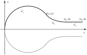
Here we propose to model the curve formed by a single sheet of graphene folding over onto itself. In this configuration we suggest that the two dominant forces are those originating from the elastic folding deformation of the graphene sheet and the van der Waals interactions between the sheet. With reference to Fig. 1, we assume a rectangular graphene sheet for which one edge folds uniformly over onto the sheet and that the consequent folding geometry both symmetric with respect to the x-axis and two-dimensional in the sense that there are no variations in the perpendicular z-direction. Furthermore, assuming a reflective symmetry in the folded geometry, we need only consider the top half of the problem. The shown curve may be divided into three parts, which are denoted by Cn where n = {1, 2, 3}. C1 is the curve from (0, 0) to (x0, y0) where the line curvature of the fold is negative, C2 is the curve from (x0, y0) to (x1, δ) where the corresponding line curvature is positive and C3 is the straight line from (x1, δ) to (x2, δ) where the line curvature is zero. We will denote the concatenation of these three regions as C = C1 + C2 + C3.
image file: c5ra08276e-f1.tif
Fig. 1 Geometry for folded graphene with total half length L.

We assume that the elastic energy Ee may be calculated by integrating the square of the curvature κ over the length of the total curve multiplied by a scaling constant γ, which is the bending rigidity of graphene. Therefore, we may write

image file: c5ra08276e-t1.tif
where κ denotes the line curvature of the curve y = y(x) and is given by
 
image file: c5ra08276e-t2.tif(1)

We now assume that the region dominated by van der Waals interactions comprises only the C3 portion of the solution curve and we model the van der Waals energy Ev using the formulation

image file: c5ra08276e-t3.tif
where image file: c5ra08276e-t33.tif is a positive constant giving the van der Waals interaction energy per area length and u(xx1) is the Heaviside unit step function. We now consider the total energy normalised by the magnitude of the bending rigidity γ which we denote by E, therefore
image file: c5ra08276e-t4.tif
where we have introduced the constant image file: c5ra08276e-t34.tif, the ratio of van der Waals interaction strength to the bending rigidity, both of which are material characteristics of graphene and therefore prescribed.

3 Variational formulation

We now employ calculus of variations to determine the shape of the curve C1 + C2, treating the quantity E as a functional of a conformation profile y = y(x) and the particular solution that we seek is the one for which E takes the minimum value. We also impose an isoperimetric constraint on the total arclength of C, namely
image file: c5ra08276e-t5.tif
which we incorporate into the variational principle using a Lagrange multiplier λ. Therefore, the functional under consideration here is given by
image file: c5ra08276e-t6.tif
Noting that both the curvature effect and the van der Waals contribution are taken into account.

Now considering the arclength constraint we comment that for C3 then y′ = 0 and ds = dx, and therefore

image file: c5ra08276e-t7.tif
and hence
image file: c5ra08276e-t8.tif

We note that L is a curved half length of the graphene sheet. Moreover, we comment that u(xx1) = 0 for C1 + C2 and κ = 0 for C3 then

image file: c5ra08276e-t9.tif

We further comment here that F depends linearly on the Lagrange multiplier λ and it takes no part in determining the shape of y = y(x) which minimises the value of F. Therefore, we are justified in choosing any value for λ and for convenience we choose λ = α. Hence, the functional we wish to minimise is given by

 
image file: c5ra08276e-t10.tif(2)
subject to the endpoint conditions y(0) = 0, and y′(0) → ∞, and at x = x1 we have a natural boundary condition on x which for a second order variational problem requires that
 
image file: c5ra08276e-t11.tif(3)
where the subscripts denote partial differentiation and f is the integrand of the functional F{y} given by
 
image file: c5ra08276e-t12.tif(4)

Also on the endpoint x = x1, we have that y(x1) = δ and y′(x1) = 0.

4 Solution to the variational problem

Since the function contains no explicit dependence on y, we may integrate the Euler–Lagrange equation once to obtain
 
image file: c5ra08276e-t13.tif(5)
where β is an arbitrary constant of integration. Furthermore, the function is also independent of x, and therefore we have
image file: c5ra08276e-t14.tif
where H is a constant. However, we know from the natural boundary condition (3) that H must equal zero at x = x1 and since H is a constant then H = 0 throughout the domain, and therefore we may deduce
image file: c5ra08276e-t15.tif
We also note that the term in parentheses is precisely the first integral of the Euler–Lagrange equation given in (5) and it is a constant, so that the solution must satisfy
fβy′ − y′′fy′′ = 0.
Now on substituting f(y′, y′′) given in (4) into this equation, we obtain
image file: c5ra08276e-t16.tif
and after some rearrangement, we may deduce
 
image file: c5ra08276e-t17.tif(6)
where again κ is the line curvature defined by (1).

We now seek a parametric solution using the substitution y′ = tan[thin space (1/6-em)]θ to obtain

image file: c5ra08276e-t18.tif
and hence parametrically we obtain the first order equations
image file: c5ra08276e-t19.tif
For convenience, we now make the substitution θ = 2ϕ − π/2, and after some rearrangement we have
 
image file: c5ra08276e-t20.tif(7)

The differential equation for x(ϕ) given in (7)1 can be integrated immediately giving

 
image file: c5ra08276e-t21.tif(8)
where c1 is an arbitrary constant.

The differential equation for y(ϕ) given in (7)2 may be rearranged as follows

image file: c5ra08276e-t22.tif
where the terms involving ϕ can be integrated as elliptic integrals of the first and second kinds, therefore we have
 
image file: c5ra08276e-t23.tif(9)
where c2 is an arbitrary constant of integration, F and E denote the incomplete elliptic integrals of the first and second kinds, respectively, and the elliptic modulus k = [2β/(α + β)]1/2.

5 Full parametric solution

Critical to the parametric solution is the point (x0, y0), where the curvature changes sign and it is also the boundary point between the two curves C1 and C2. This point corresponds to the parameter value ϕ = ϕ0, where ϕ0 = sin−1(1/k).

On the curve C1, the solution varies over the range ϕ = [0, ϕ0] starting at the origin and having a trajectory that is upward and bending to the right half of the plane. To satisfy these requirements we require

image file: c5ra08276e-t24.tif
where the starting point (0, 0) has been used to determine that c1 = 2(α + β)1/2/β and c2 = 0. This means the critical point (x0, y0) is given by
image file: c5ra08276e-t25.tif

For C2 we change the signs adopted from the general solutions (8) and (9), and we require that the solution for C1 and C2 are continuous at (x0, y0), which leads to the solution given by

image file: c5ra08276e-t26.tif
where ϕ ∈ [π/4, ϕ0], and again F and E are the incomplete elliptic integrals of the first and second kinds, respectively.

The parameter value α corresponds to the material characteristics where it is defined as the ratio of the van der Waals interaction image file: c5ra08276e-t33.tif, to the bending rigidity γ. For the graphene, it was estimated by Spanu et al.26 that image file: c5ra08276e-t33.tif ≈ 0.0214 eV Å−2. Following the work by Wei et al.,7 the possible values of γ range from 0.800 to 1.60 eV. Therefore, we have the corresponding values of α in the range of 0.0268 to 0.0134 Å−2. In fact, the shape function or the folding conformation is a function of γ, and it can depend on the number of defects and the number of dopings. Indirectly, the folding conformation could therefore indicate the presence of defects and dopings.

To determine the remaining unknown β, we use the endpoint image file: c5ra08276e-t27.tif, where δ is a half of the separation distance between the folded graphene in the parallel region, and we adopt the value δ ≈ 1.66 Å.27 Solving this equation numerically, the value of β can be determined. A plot of five possible folded graphenes is shown in Fig. 2, and the numerical values are presented in Table 1.


image file: c5ra08276e-f2.tif
Fig. 2 Fold region for various values of bending rigidity γ.
Table 1 Numerical values for graphene folding using van der Waals interaction image file: c5ra08276e-t33.tif to be 0.0214 eV Å−2 (ref. 26)
γ (eV) x0 (Å) y0 (Å) Lmin (Å)
0.800 7.88 2.50 13.7
1.00 9.19 2.74 16.2
1.20 10.3 2.95 18.3
1.40 11.4 3.15 20.2
1.60 12.3 3.32 22.0


By integrating ds over both of the curves C1 + C2, we may determine the arclength of the extremal curve and this provides a lower bound to L for this solution to be physically meaningful, and we may deduce

image file: c5ra08276e-t28.tif
where dx/dϕ and dy/dϕ are given in (7). Finally, we have
 
image file: c5ra08276e-t29.tif(10)
where Lmin is a lower bound to the half length L.

The total energy for the folded graphene is

image file: c5ra08276e-t30.tif
and on changing the integration variable using y′ = tan[thin space (1/6-em)]θ, we may deduce
image file: c5ra08276e-t31.tif

Again, we use θ = 2ϕ − π/2 so that Etot can be evaluated in terms of elliptic integrals of the second kind and the final expression becomes

 
image file: c5ra08276e-t32.tif(11)
We note that E(0, k) = 0 and (x2x1) = LLmin. Fig. 3 shows the relation between the total energy Etot of the folded graphene and the total half length L, and the system is stable provided that the total energy is negative. For a bending rigidity γ = 1.40 eV, we require that the graphene sheet have a half length of at least 45 Å for the folding behaviour to occur and this is in agreement with Meng et al.18


image file: c5ra08276e-f3.tif
Fig. 3 Relation between total energy Etot and total half length L where L for LLmin.

Furthermore, the folding conformations obtained by this model are also adopted to compare with the folding images taken by Lopez-Bezanilla et al.12 and they are as shown in Fig. 4. We observe that the best fit profiles shown in Fig. 4 (top) and (bottom) are obtained by using different bending rigidity values which are γ = 1.00 eV (navy colour) and γ = 1.60 eV (purple colour), respectively. Note that the model presented here is derived only for a single layer of graphene, and the different values for γ are due to the increased bending rigidity for multi-layers. Moreover, the five folding conformations in each figure are obtained independently but they are plotted on the same coordinates for the purpose of comparison. Overall, the folding geometry of graphene as determined here by the variational calculus provides a simple model but correctly describes the folding profile observed in experiments.


image file: c5ra08276e-f4.tif
Fig. 4 Folding conformations obtained by present model superimposed upon the images taken by high-resolution transmission electron microscopy12 where the proposed model perfectly matches with (top) γ = 1.00 eV represented by the navy line and (bottom) γ = 1.60 eV represented by the purple line (adapted with permission from Lopez-Bezanilla et al.12 Copyright 2012 American Chemical Society).

6 Summary

In this paper, we use a calculus of variations approach to determine the shape of folded graphene sheets. The calculus of variations is utilised to minimise the elastic energy arising from the curvature squared while maximising the van der Waals energy in the parallel region. In addition, the fold is assumed to have a translational symmetry along the fold, so that the problem may be reduced to a two dimensional problem with reflective symmetry across the fold. Here, the van der Waals interaction is assumed to be 0.0214 eV Å−2 and with a separation distance in the parallel region fixed to be 1.66 Å. However, the bending rigidity of graphene is selected in the range from 0.800 to 1.60 eV. An analytical parametric solution is obtained and numerical values for the critical points where the curvature changes the sign and where the folded graphene assumes a parallel orientation are determined. Furthermore, the model predicts the critical length of a graphene sheet needed to adopt an energetically stable folded conformation that depends on the actual value of the bending rigidity adopted for the graphene sheet.

References

  1. J. S. Bunch, A. M. van der Zande, S. S. Verbridge, I. W. Frank, D. M. Tanenbaum, J. M. Parpia, H. G. Craighead and P. L. McEuen, Electromechanical resonators from graphene sheets, Science, 2007, 315, 490–493 CrossRef CAS PubMed.
  2. K.-T. Lam, C. Lee and G. Liang, Bilayer graphene nanoribbon nanoelectromechanical system device: a computational study, Appl. Phys. Lett., 2009, 95, 143107 CrossRef PubMed.
  3. M. Poetschke, C. G. Rocha, L. E. F. Foa Torres, S. Roche and G. Cuniberti, Modeling graphene-based nanoelectromechanical devices, Phys. Rev. B: Condens. Matter Mater. Phys., 2010, 81, 193404 CrossRef.
  4. X. Sun, Z. Liu, K. Welsher, J. T. Robinson, A. Goodwin, S. Zaric and H. Dai, Nano-graphene oxide for cellular imaging and drug delivery, Nano Res., 2008, 1, 203–212 CrossRef CAS PubMed.
  5. H. Jiang, Chemical preparation of graphene-based nanomaterials and their applications in chemical and biological sensors, Small, 2011, 7, 2413–2427 CAS.
  6. Y. Wang, Z. Li, J. Wang, J. Li and Y. Lin, Graphene and graphene oxide: biofunctionalization and applications in biotechnology, Trends Biotechnol., 2011, 29, 205–212 CrossRef CAS PubMed.
  7. Y. Wei, B. Wang, J. Wu, R. Yang and M. L. Dunn, Bending rigidity and Gaussian bending stiffness of single-layered graphene, Nano Lett., 2013, 13, 26–30 CrossRef CAS PubMed.
  8. K. Nakada, M. Fujita, G. Dresselhaus and M. S. Dresselhaus, Edge state in graphene ribbons: Nanometer size effect and edge shape dependence, Phys. Rev. B: Condens. Matter, 1996, 54, 17954 CrossRef CAS.
  9. T. Enokia, Y. Kobayashia and K.-I. Fukuia, Electronic structures of graphene edges and nanographene, Int. Rev. Phys. Chem., 2007, 26, 609–645 CrossRef PubMed.
  10. K. A. Ritter and J. W. Lyding, The influence of edge structure on the electronic properties of graphene quantum dots and nanoribbons, Nat. Mater., 2009, 8, 235–242 CrossRef CAS PubMed.
  11. J. Feng, L. Qi, J. Y. Huang and J. Li, Geometric and electronic structure of graphene bilayer edges, Phys. Rev. B: Condens. Matter Mater. Phys., 2009, 80, 165407 CrossRef.
  12. A. Lopez-Bezanilla, J. Campos-Delgado, B. G. Sumpter, D. L. Baptista, T. Hayashi, Y. A. Kim, H. Muramatsu, M. Endo, C. A. Achete, M. Terrones and V. Meunier, Geometric and electronic structure of closed graphene edges, J. Phys. Chem. Lett., 2012, 3, 2097–2102 CrossRef CAS.
  13. D. Rainis, F. Taddei, M. Polini, G. Leon, F. Guinea and V. I. Falko, Gauge fields and interferometry in folded graphene, Phys. Rev. B: Condens. Matter Mater. Phys., 2011, 83, 165403 CrossRef.
  14. K. V. Zakharchenko, M. I. Katsnelson and A. Fasolino, Finite temperature lattice properties of graphene beyond the quasiharmonic approximation, Phys. Rev. Lett., 2009, 102, 046808 CrossRef CAS.
  15. C. Lee, X. Wei, J. W. Kysar and J. Hone, Measurement of the elastic properties and intrinsic strength of monolayer graphene, Science, 2008, 321, 385–388 CrossRef CAS PubMed.
  16. H. C. Schniepp, K. N. Kudin, J.-L. Li, R. K. Prudhomme, R. Car, D. A. Saville and I. A. Aksay, Bending properties of single functionalized graphene sheets probed by atomic force microscopy, ACS Nano, 2008, 2, 2577–2584 CrossRef CAS PubMed.
  17. J. Zhang, J. Xiao, X. Meng, C. Monroe, Y. Huang and J.-M. Zuo, Free folding of suspended graphene sheets by random mechanical stimulation, Phys. Rev. Lett., 2010, 104, 166805 CrossRef.
  18. X. Meng, M. Li, Z. Kang, X. Zhang and J. Xiao, Mechanics of self-folding of single-layer graphene, J. Phys. D: Appl. Phys., 2013, 46, 055308 CrossRef.
  19. S. Cranford, D. Sen and M. J. Buehler, Meso-origami: Folding multilayer graphene sheets, Appl. Phys. Lett., 2009, 95, 123121 CrossRef PubMed.
  20. H. Hu, Z. Zhao, W. Wan, Y. Gogotsi and J. Qiu, Ultralight and highly compressible graphene aerogels, Adv. Mater., 2013, 25, 2219–2223 CrossRef CAS PubMed.
  21. J. Zang, A. Treibergs, Y. Han and F. Liu, Geometric constant defining shape transitions of carbon nanotubes under pressure, Phys. Rev. Lett., 2004, 92, 105501 CrossRef.
  22. C. Li and T.-W. Chou, A structural mechanics approach for the analysis of carbon nanotubes, Int. J. Solids Struct., 2003, 40, 2487–2499 CrossRef.
  23. Y. Jin and F. G. Yuan, Simulation of elastic properties of single-walled carbon nanotubes, Compos. Sci. Technol., 2003, 63, 1507–1515 CrossRef CAS.
  24. T. Natsuki, K. Tantrakarn and M. Endo, Effects of carbon nanotube structures on mechanical properties, Appl. Phys. A: Mater. Sci. Process., 2004, 79, 117–124 CrossRef CAS.
  25. D. Baowan, B. J. Cox and J. M. Hill, Determination of join region between carbon nanostructures using variational calculus, ANZIAM J., 2013, 54, 221–247 CrossRef.
  26. L. Spanu, S. Sorella and G. Galli, Nature and strength of interlayer binding in graphite, Phys. Rev. Lett., 2009, 103, 196401 CrossRef.
  27. L. A. Girifalco, M. Hodak and R. S. Lee, Carbon nanotubes, buckyballs, ropes, and a universal graphitic potential, Phys. Rev. B: Condens. Matter, 2000, 62, 13104–13110 CrossRef CAS.

This journal is © The Royal Society of Chemistry 2015
Click here to see how this site uses Cookies. View our privacy policy here.