A facile approach to prepare strong poly(acrylic acid)/LAPONITE® ionic nanocomposite hydrogels at high clay concentrations
Juan Du,
Jinlong Zhu,
Ronglan Wu,
Shimei Xu*,
Yun Tan and
Jide Wang
Key Laboratory of Oil and Gas Fine Chemicals, Ministry of Education and Xinjiang Uyghur Autonomous Region, College of Chemistry and Chemical Engineering, Xinjiang University, Urumqi, Xinjiang 830046, People’s Republic of China. E-mail: xushmei@hotmail.com; Fax: +86 991 8581018; Tel: +86 991 8583972
First published on 1st July 2015
Abstract
A facile strategy was developed to prepare mechanically strong LAPONITE®-based ionic nanocomposite (NC) hydrogels at high clay concentrations. Based on the thixotropy of an acrylic acid (AA)/LAPONITE® dispersion, a series of ionic poly(acrylic acid) (PAA)/LAPONITE® NC hydrogels were successfully prepared without the addition of additional dispersing monomers. Fourier transform infrared (FTIR) spectroscopy and thermogravimetric (TG) analysis demonstrated the composition and thermostability of the NC hydrogels, respectively. The network of the hydrogels was examined by scanning electron microscopy (SEM), and the dispersion of LAPONITE® nanoplatelets in the ionic hydrogels was investigated by X-ray diffraction (XRD) and transmission electron microscopy (TEM). The hydrogels exhibited viscoelastic solid-like properties, as revealed by dynamic mechanical analysis (DMA) within a linear viscoelasticity region, and demonstrated that the network structure was formed with the junction of the ionic AA monomer and the LAPONITE® platelets. The hydrogels showed improved mechanical properties (i.e. tensile strength: 308 kPa, elongation at break: 1110%), which were due to more effective cross-link points provided by the high content of LAPONITE® and the entanglements among the PAA chains. This approach is synthetically simple and dramatically increases the choice of strong hydrogels for applications.
1 Introduction
Over the last few years, the utility of inorganic nanoscale particles as fillers to enhance the performance of polymer has been established. Of particular interest is nanocomposite technology consisting of a unique organic (polymer)/inorganic (clay) network structure, because they often exhibit remarkably improved mechanical properties as compared with those of virgin polymers or conventional composites (micro/macro-composites).1–11 These concurrent property improvements are well beyond what can be generally achieved through the preparation of micro/macro-composites. It is well known that the clay content plays an important role in the mechanical properties of nanocomposite (NC) hydrogels. An increase in LAPONITE® content usually enhances gel strength.2,3,5,10,12 LAPONITE®, carrying strong negative charges on the surface and weak positive charges on the rim, can form a clear and colorless colloidal dispersion in water, which is stabilized by the repulsive electrostatic interaction.10,13–16 However, it is hard to prepare high concentrations of LAPONITE® aqueous dispersions, even using special mixers, due to the high viscosity caused by the electrostatic attraction among surfaces and edges of different clay discs. Thus, the LAPONITE® concentration during the preparation of reported NC hydrogels was usually below 10 wt% (against water). To combat the problem, Zhu et al. used Na4P2O7-modified LAPONITE® to successfully prepare a poly(N-isopropylacrylamide)/clay NC hydrogel under a clay concentration of 15 wt%, since the edge of the clay discs were negatively charged after modification and thus prohibited the formation of a ‘House of Cards’ structure.10 Occasionally, a special fractional step method was reported to produce a clay dispersion of 20 wt% (25 mol%, against water) and fabricate a series of poly(N-isopropylacrylamide)/LAPONITE® NC hydrogels. However, a complex mixing process and temperature control was needed before polymerization.17Typically, NC hydrogels have been composed of nonionic monomers crosslinked by LAPONITE® due to the special colloid properties of LAPONITE®.8,10,12,14,18–22 There has been limited success in the preparation of ionic NC hydrogels. Aggregation and gelation occurred when ionic monomers were added to the clay dispersion, therefore resulting in poor optical and mechanical properties of the ionic NC hydrogels. Numerous attempts to overcome the problem have been reported thus far, in which two main strategies were developed: (1) using nonionic monomers to pre-adsorb onto the surface of LAPONITE® before further polymerization of ionic monomers;13,23–28 (2) choosing specific ionic monomers to realize good dispersion of LAPONITE®.29–31
In our previous work, transparent ionic NC hydrogels cross-linked by LAPONITE® XLG were successfully synthesized via the in situ free radical polymerization of AA with the assistance of 2-acrylamido-2-methylpropanesulphonic acid (AMPS)29 and sodium dodecyl sulfate (SDS),32 and the ultimate tensile strengths could reach 189 kPa and 162 kPa, respectively. The addition of AMPS or SDS can successfully avoid the aggregation of LAPONITE® in the ionic AA monomer. During the research process above, we found that LAPONITE®/AA aqueous dispersions under high clay concentrations had remarkable thixotropy. The monomers tightly stuck onto the clay discs without precipitation because of the high viscosity of the dispersion. However, under constant stirring, the mixtures exhibited a shear thinning behavior. This made it possible to obtain a uniform reaction system by simply mixing all the reagents under stirring. Then the homogeneous mixture underwent polymerization without stirring to get an ionic PAA/LAPONITE® NC hydrogel. Being intrigued with this phenomenon, we developed a facile one-pot process to prepare ionic NC hydrogels at high clay concentrations in the presence of ionic monomers without additional dispersing monomers. To the best of our knowledge, this is the first report in which strong ionic PAA/LAPONITE® hydrogels are prepared by the direct addition of AA into a LAPONITE® dispersion followed by in situ polymerization. The NC hydrogels exhibited improved mechanical properties and would have potential applications in biomedical and tissue engineering.
2 Experimental
2.1 Materials
LAPONITE® XLG (Mg5.34Li0.66Si8O20(OH)4Na0.66, Rockwood, USA), acrylic acid (AA, Tianjin Fuchen Chemical Reagents Factory, China), N,N′-methylenebisacrylamide (BIS, Tianjin Guangfu Institute of Fine Chemicals, China), potassium persulfate (KPS, Beijing Beihua Fine Chemicals Co., Ltd., China), sodium hydroxide (NaOH, Shanghai Kechang Fine Chemicals Company, China), and tetrasodium pyrophosphate (Na4P2O7, Shanghai Kechang Fine Chemicals Company, China) were used as received. Deionized water was used in all experiments.2.2 Synthesis of the hydrogels
Typically, 1.12 g LAPONITE® was dispersed in 8 mL of deionized water under stirring for 20 min to make a 14 wt% LAPONITE® dispersion (against H2O). Then, a desired amount of Na4P2O7 was added into the dispersion to reduce the viscosity. The mass ratio of Na4P2O7 to LAPONITE® was kept at 0.0768![[thin space (1/6-em)]](https://www.rsc.org/images/entities/char_2009.gif) :
:![[thin space (1/6-em)]](https://www.rsc.org/images/entities/char_2009.gif) 1.10 Whereafter, 6.0 mL AA, which was neutralized to a degree of 40 mol% by 30 wt% NaOH solution in an ice bath beforehand, was added into Na4P2O7-modified LAPONITE® dispersions. The mixture was ultrasonicated for 5 min, and afterward stirred for 20 min followed by the addition of 8.7 wt% KPS (relative to the weight of AA). Polymerization was performed in airtight glass tubes in a water bath at 50 °C for 72 hours. After polymerization, the as-prepared hydrogels were removed, cut into disks, and then soaked in a large amount of deionized water for 1 week. The water was exchanged every 2 days for the removal of monomers and oligomers which were not actually incorporated into the hydrogels. After at least 1 week, the PAA/LAPONITE® hydrogels were dried in an oven at 80 °C until a constant weight was obtained.
1.10 Whereafter, 6.0 mL AA, which was neutralized to a degree of 40 mol% by 30 wt% NaOH solution in an ice bath beforehand, was added into Na4P2O7-modified LAPONITE® dispersions. The mixture was ultrasonicated for 5 min, and afterward stirred for 20 min followed by the addition of 8.7 wt% KPS (relative to the weight of AA). Polymerization was performed in airtight glass tubes in a water bath at 50 °C for 72 hours. After polymerization, the as-prepared hydrogels were removed, cut into disks, and then soaked in a large amount of deionized water for 1 week. The water was exchanged every 2 days for the removal of monomers and oligomers which were not actually incorporated into the hydrogels. After at least 1 week, the PAA/LAPONITE® hydrogels were dried in an oven at 80 °C until a constant weight was obtained.
As a control, organically crosslinked gels were prepared according to the procedure above, except 0.04 wt% BIS (relative to the weight of AA) was used instead of Na4P2O7 and LAPONITE®.
2.3 Characterization
Rheology measurements were carried out on a stress-controlled Discovery HR-1 rheometer using parallel platelets of 25 mm diameter at 25 °C. A thin layer of silicon oil was laid on the rim of the fixture to prevent water evaporation and CO2 dissolution. The viscosity of the dispersion was measured with a shear rate of 50 s−1. Before every measurement of thixotropy, all the AA/LAPONITE® dispersions were preliminarily aged for 1 hour, followed by a 300 second steady pre-shear at 10 s−1 to achieve a reproducible initial state. Then, the steady flow measurements of the AA/LAPONITE® dispersions were carried out in the range of shear rates from 10−3 s−1 to 3000 s−1 to determine the shear viscosity and shear stress.Fourier transform infrared (FTIR) spectra were obtained using a Bruker Eqinox 55 spectrometer with milled dried NC gels by the conventional KBr disk method in the range of 400–4000 cm−1 with 2 cm−1 of spectral resolution. X-ray diffraction (XRD) patterns were performed using a Bruker D8 Advance X-ray diffractometer (40 kV, 100 mA) equipped with Cu Kα X-ray (λ = 0.154 nm) scanning in a step of 1° min−1 from 2° to 15°. Transmission electron microscopy (TEM) was conducted with a Hitachi H-600 transmission electron microscope with an accelerating voltage of 100 kV. Ultrathin films were prepared for TEM observation by cutting dried gels embedded in epoxy resin using an ultramicrotome. Scanning electron microscopy (SEM) images of the samples were obtained using a LEO-1430VP at an accelerating voltage of 20 kV. The hydrogels were allowed to reach equilibrium in deionized water overnight prior to freeze-drying (FD-1C-50) for 48 hours. Then, the hydrogels were coated with gold prior to SEM analysis. Thermogravimetric (TG) analyses were carried out using a TG/DTA STA-449F3 (NETZSCH) instrument, heating samples from 30 to 800 °C at a heating rate of 10 °C min−1 in an air flow. The clay content in the NC dried gels was evaluated from the residual weight at 800 °C. All the hydrogels for the TG test were neutralized by 36 wt% HCl for 24 hours first, then filtered, and finally washed with deionized water until no Cl− was found in the filtrate. The residue was dried in an oven at 80 °C before the test until a constant weight was obtained.
Dynamic mechanical analysis (DMA) was conducted on the as-synthesized NC gel samples to estimate the viscoelasticity of PAA/LAPONITE® NC hydrogels with a dynamic mechanical analyzer (DMA Q800, TA Instruments) with a tension fixture. The gel sample stuck well to the fixture without any slippage. Silicone oil was laid on the edge of the fixture platelets to prevent solvent evaporation. First, the dynamic strain sweep was carried out at a constant frequency of 1 Hz to determine the linear viscoelasticity region. Then, the frequency sweep was performed over the frequency range of 0.01 to 100 Hz. The dynamic frequency sweep was measured at a constant strain of 0.1%. All dynamic mechanical tests were carried out at 30 °C.
Tensile measurements were performed on as-prepared gels of the same size (5.5 mm diameter × 60 mm length) with a static mechanical tester (H5KT, Tinius Olsen, USA) at 25 °C. The sample length between the jaws was 20 mm and the crosshead speed was 100 mm min−1. The tensile strain was taken as the length change related to the original length and the tensile strength was estimated on the cross section of the original sample. All the samples were performed in triplicate, and the average values are reported.
3 Results and discussion
3.1 Interaction between clay and AA
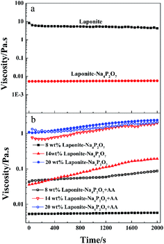
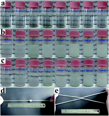
When the LAPONITE® XLG was dispersed in water at a clay concentration higher than 2 wt% for a definite time (different times for different concentrations), the clay discs would form a ‘House of Cards’ structure, due to the electrostatic attraction among the surfaces and edges of different discs, whereupon the mixture became very viscous.10,13–16,33 This made it hard to mix with monomers or other reagents by normal mixing methods, which was the reason why most of the NC hydrogels were prepared at low clay concentrations. Besides, direct addition of even a small amount of ionic monomer into the LAPONITE® dispersion induced gelation and the clay dispersion quickly became subsided and opaque due to the decrease of the Debye distance for the electrostatic repulsion.13,23–26,29,32–34 So it has been challenging to synthesize ionic NC hydrogels at high LAPONITE® concentrations.LAPONITE® XLG had a certain fluidity when the LAPONITE® was modified by Na4P2O7, even at high clay concentrations (above 8 wt%), which made it possible to obtain a uniform dispersion of LAPONITE® and monomers by mixing (Fig. 1a). The viscosity increased with increasing concentrations of LAPONITE® because of the electrostatic interaction among the surfaces and edges of different LAPONITE® platelets. The addition of AA induced the instability of the dispersion, and showed a slight increase in viscosity with measurement time (Fig. 1b). The transparent LAPONITE® dispersion (Fig. 2a) showed a steep decrease in transmittance and became opaque, while the viscosity simultaneously increased steeply (Fig. 2b). These facts suggested that aggregates formed in the dispersion because of the decreased electrostatic repulsion among the LAPONITE® platelets caused by increased ionic strength. The mixtures will separate into two layers after standing for several hours when the LAPONITE® concentration was less than 8 wt% in AA/LAPONITE® system (Fig. 2c). However, further to increase LAPONITE® concentration to 8 wt% or more, the dispersion remained stable without stratification and settlement after standing in 50 °C water bath more than 12 hours. More importantly, the dispersion exhibited quite good flowability under stirring (Fig. 3). This made it possible to mix all reactants to obtain uniform precursor system. As a result, homogeneous ionic NC hydrogel can be produced via in situ copolymerization of AA in the Na4P2O7-modified LAPONITE® dispersion without the help of other dispersing reagents (Fig. 2d and e).
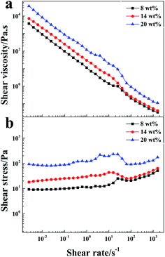 | ||
| Fig. 3 Shear viscosity and shear stress vs. shear rate for the dispersions of AA/Na4P2O7-modified LAPONITE® at different LAPONITE® concentrations (from 8 wt% to 20 wt%). | ||
3.2 Formation of the network structure
FT-IR studies were conducted to investigate the gel formation between PAA and the LAPONITE® platelets (Fig. 4). The absorption bands of LAPONITE® at 1012 and 461 cm−1, could be ascribed to Si–O stretching (in-plane) and Si–O bending modes, respectively (Fig. 4a).35,36 Compared with the FTIR spectrum of LAPONITE® (Fig. 4a), the absorption bands of LAPONITE® at 1172–1177 cm−1, 1074–1105 cm−1 and 465–469 cm−1 were obviously observed in the spectrum of the PAA/LAPONITE® hydrogel, suggesting that LAPONITE® is incorporated in the hydrogel. Besides, small additional peaks appeared between 600 and 800 cm−1, which confirmed the presence of metal-oxide stretching vibrations in the PAA/LAPONITE® NC hydrogels (due to clay).37,38 In Fig. 4c–e, a series of new absorption bands at 1717–1726 cm−1 (C![[double bond, length as m-dash]](https://www.rsc.org/images/entities/char_e001.gif) O stretching of –COOH group), 1568–1572 cm−1 and 1453–1457 cm−1 (asymmetric and symmetric stretching –COO− groups) appeared in the spectra of the PAA/LAPONITE® hydrogels (Fig. 4c–e), indicating the existence of PAA chains. We had not found any absorption peak of unsaturated C
O stretching of –COOH group), 1568–1572 cm−1 and 1453–1457 cm−1 (asymmetric and symmetric stretching –COO− groups) appeared in the spectra of the PAA/LAPONITE® hydrogels (Fig. 4c–e), indicating the existence of PAA chains. We had not found any absorption peak of unsaturated C![[double bond, length as m-dash]](https://www.rsc.org/images/entities/char_e001.gif) C bonds at 1630 cm−1, which gave an eloquent proof that AA was successfully polymerized. Furthermore, the absorption bands of –COOH groups and –COO− groups generated an obvious blue shift effect (from 1717 to 1726 cm−1 for the –COOH group and from 1568 to 1572 cm−1 for the –COO− group, respectively) with the increase of LAPONITE® concentrations from 8 wt% to 20 wt% (Fig. 4c–e), which suggested that the cross-linked network had formed. These results indicated that the carboxylic groups of PAA were dissociated into COO− groups, which formed a complex with LAPONITE® through electrostatic interaction during the polymerization procedure.
C bonds at 1630 cm−1, which gave an eloquent proof that AA was successfully polymerized. Furthermore, the absorption bands of –COOH groups and –COO− groups generated an obvious blue shift effect (from 1717 to 1726 cm−1 for the –COOH group and from 1568 to 1572 cm−1 for the –COO− group, respectively) with the increase of LAPONITE® concentrations from 8 wt% to 20 wt% (Fig. 4c–e), which suggested that the cross-linked network had formed. These results indicated that the carboxylic groups of PAA were dissociated into COO− groups, which formed a complex with LAPONITE® through electrostatic interaction during the polymerization procedure.
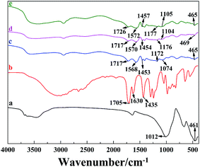 | ||
| Fig. 4 FT-IR spectra of (a) clay, (b) AA, and PAA/LAPONITE® NC hydrogels at different LAPONITE® concentrations: (c) 8 wt%, (d) 14 wt% and (e) 20 wt% (the degree of neutralization is 40 mol%). | ||
The microstructure of freeze-dried hydrogels was analyzed via SEM (Fig. 5). We noticed that the hydrogels presented large interconnected pores with pore size of 20–120 μm, while the thinness of the pore walls were in several micrometers. Furthermore, the pores tended to be connected to each other and formed some open channels, which could remarkably facilitate the migration of water in and out of the NC gels when the gels swelled in the water.
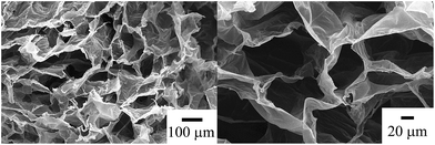 | ||
| Fig. 5 SEM photos for freeze-dried PAA/LAPONITE® NC hydrogels at 14 wt% LAPONITE® and 40 mol% degree of neutralization ((a) original magnification 300×, (b) original magnification 1000×). | ||
Fig. 6 shows the XRD patterns of the PAA/LAPONITE® NC hydrogel to observe the distribution of LAPONITE®. Pure LAPONITE® exhibited a diffraction peak at about 2θ = 4.88–6.89°, corresponding to a basal spacing between the LAPONITE® platelets.28 In the case of the ionic NC hydrogels with different concentrations of LAPONITE® (from 8 wt% to 20 wt%), no distinct diffraction peaks were observed in the range of 2θ from 2° to 8°. This meant that there was no regular stacking of LAPONITE® in the dried NC gels. The peaks near 10° were due to the existence of polyacrylate in the ionic NC hydrogels.39,40
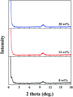 | ||
| Fig. 6 XRD patterns for LAPONITE® and PAA/LAPONITE® ionic NC hydrogels at different LAPONITE® concentrations (the degree of neutralization is 40 mol%). | ||
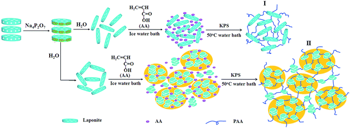
The dispersion of clay platelets in the hydrogels was further investigated by TEM measurements (Fig. 7). It was shown that, even in the dried gel, LAPONITE® was substantially exfoliated and dispersed uniformly by the polymer matrix when the clay content was low (Fig. 7a), while part of the clay nanosheets existed as small aggregates when the LAPONITE® content was higher than 8 wt% (Fig. 7b and c). This phenomenon was more obvious in a concentration of 20 wt% LAPONITE®. The exfoliated clay platelets or small aggregates were coexistent in the PAA/LAPONITE® hydrogels. According to the mechanism for the NC hydrogels suggested by Haraguchi,18 the clay particles tended to cleave into single disk-like units that were 30 nm in diameter and 1 nm thick when dispersed in water.41,42 These then acted as multifunctional crosslinkers, which interacted with nonionic polymers by polar or coordination interaction. However, in our work, two mechanisms coexisted for the formation of the ionic NC hydrogels because of two dispersing states of LAPONITE® in the polymer matrixes: mono-nanosheets and small aggregates (Scheme 1). The exfoliated clay platelets or small aggregates and AA monomer were dispersed homogeneously in the initial reaction system. The initiator, KPS, was closely associated on the clay surfaces because of the strong ionic interactions between the KPS and clay. As a result, a free-radical reaction occurred on the clay surfaces, and thus the PAA chains were attached to the clay platelets forming a network structure by polar or electrostatic interaction. In contrast, the crosslinking of LAPONITE® in mechanism II was not as effective as the one in mechanism I, due to the partial aggregation of LAPONITE®.
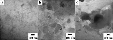 | ||
| Fig. 7 TEM of PAA/LAPONITE® NC hydrogels at different LAPONITE® concentrations: (a) 8 wt%, (b) 14 wt% and (c) 20 wt% (the degree of neutralization is 40 mol%). | ||
3.3 Thermogravimetric analysis
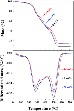
The thermal stability of the PAA/LAPONITE® hydrogels was investigated using thermogravimetric analysis (TGA). The TG curves of the samples prepared under different concentrations of LAPONITE® (from 8 wt% to 20 wt%) are shown in Fig. 8. The TGA traces indicated that there were three major steps during the decomposition of the hydrogel. The differentiated TGA (DTGA) traces displayed two large and one small peak above 200 °C for all the hydrogels. The peak at around 280 °C (279 °C for 8 wt% LAPONITE®, 281 °C for 14 wt% LAPONITE®, and 276 °C for 20 wt% LAPONITE®) and a small peak at 360 °C (355 °C for 8 wt% LAPONITE®, 365 °C for 14 wt% LAPONITE®, and 352 °C for 20 wt% LAPONITE®) were coupled to decomposition step one and two, which were attributed to the evaporation of water and decomposition of some functional groups, such as carboxyl groups in the polymer chains, accordingly. The other peaks at around 500 °C (503 °C for 8 wt% LAPONITE®, 517 °C for 14 wt% LAPONITE® and 494 °C for 20 wt% LAPONITE®), came from the decomposition of the polymeric network. The final residual char yields were 7.88 wt%, 13.60 wt% and 13.89 wt%. It could be concluded from all the above results that the NC gels containing 13.60 wt% clay possessed higher thermal stability than those of 7.88 wt%, which indicated that the thermal stability of the PAA/LAPONITE® hydrogels was enhanced by the incorporation of only a small amount of clay nanolayers. It implied that most of the clay platelets in the NC hydrogels acted as crosslinkers and the polymer chains were attached on their surface. However, the gels prepared under a concentration of 20 wt% LAPONITE® contained a clay content of only 13.89 wt%, which did not exhibit better thermal stability than the ones under a concentration of 14 wt% LAPONITE®, as we predicted. This was probably because that the clay discs at high concentrations were inclined to stack together and formed small aggregates. As a result, the small aggregates cannot show as effective crosslinking as exfoliated ones. During the washing after polymerization, some soluble inorganics were eluted away, resulting in the lower than expected char yields. Generally, there was no significant difference found in the thermal stability of the hydrogels. This indicated that the effective crosslinking and dispersing states of LAPONITE® acted as important roles in the thermal properties of the NC hydrogels.3.4 Mechanical properties
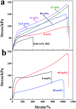
Stress–strain curves of the hydrogels are shown in Fig. 9 (mechanical factors are given in Table 1 accordingly). The maximum strength reached 308 kPa with elongation at break of 1110% for the NC gels at a LAPONITE® concentration of 14 wt% (Fig. 9a). This was much higher than the chemically crosslinked hydrogels, which exhibited poor mechanical properties and broke at a low stress of 87 kPa with a relative low strain of 408% (0.04 wt% BIS content) (Fig. 9a). The tensile strength was also much higher than the poly(AMPS-co-AA)/LAPONITE® NC gels (189 kPa) recently prepared by our group.29 In this NC gel system, LAPONITE® acted as a multi-functional cross-linker to fabricate a unique polymer/clay network structure.1,43 Generally, an increase of LAPONITE® content in the hydrogel led to an increase of the crosslinking density. As a result, the tensile strength was enhanced. However, further to the increase of the LAPONITE® concentration to 20 wt%, a decrease in the tensile stress of the hydrogel was observed instead. According to the TEM morphology (Fig. 7), some clay discs stacked together and formed small aggregates in higher LAPONITE® concentrations, which reduced the efficiency of crosslinking and caused the decreased tensile strength.| Clay concentration (wt%) | Fracture stress (kPa) | Fracture strain (%) | Elastic modulus (kPa) | Dissipated energy (MJ m−3) |
|---|---|---|---|---|
| 8 | 159.23 | 1131.20 | 157.51 | 1.29 |
| 11.5 | 240.37 | 1089.00 | 131.25 | 1.81 |
| 14 | 308.00 | 1110.00 | 75.70 | 2.19 |
| 17 | 297.56 | 1114.10 | 127.00 | 1.94 |
| 20 | 219.82 | 1109.90 | 131.48 | 1.54 |
In contrast, the hydrogels prepared at a concentration of 14 wt% LAPONITE® showed the highest tensile strength but in a low elastic modulus.
The degree of neutralization of AA caused an effect not only on the dispersion of LAPONITE®, but also on the mechanical properties of the hydrogels. Fig. 9b shows the stress–strain curves of the hydrogels prepared with 14 wt% LAPONITE®. The tensile strength increased from 186 kPa to 308 kPa when the degree of neutralization increased to 40 mol%, and then fell rapidly to 132 kPa when the neutralization degree was further increased to 80 mol%. At a low neutralization degree, polymer chains were curly since more –COOH groups existed, which was not conducive to hydrogel strength. Along with the increasing degree of neutralization, –COOH groups in the polymer chains were deprotonized and the polymer chains were expanded and entangled to some degree, which made a big contribution to the high gel strength. A further increase in the neutralization degree (larger than 40 mol%) made the electrostatic interaction of charged groups on the elastic free energy decrease. Thus, the tensile strength decreased.44 Generally, the ionic PAA/LAPONITE® NC hydrogels exhibited a robust mechanical behavior under large deformations.
3.5 Dynamic mechanical analysis
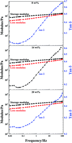
DMA is a nondestructive method used to characterize the viscoelastic properties of materials. To further study the effect of LAPONITE® on the mechanical performance of the PAA/LAPONITE® hydrogels, the dynamic viscoelasticity of the hydrogels was examined by a dynamic mechanical analyzer. To determine the linear viscoelasticity region, a strain sweep from 0.1% to 100% strain was then conducted at a frequency of 1.0 Hz and 30 °C on the fully formed NC hydrogels. After strain sweeps, a strain of 0.1% was selected for subsequent frequency sweeps to ensure the availability of the linear viscoelasticity and enough sensitivity.45Dynamic frequency sweep tests were performed in the linear viscoelastic range to determine the frequency dependence of the storage modulus (G′) and loss modulus (G′′).46 The storage modulus G′ describes the stiffness or elastic character of a material and the loss modulus G′′ describes its viscous properties. In this section, G′, G′′ and tan![[thin space (1/6-em)]](https://www.rsc.org/images/entities/char_2009.gif) δ (loss factor) of the NC hydrogels with different concentrations of LAPONITE® are presented in Fig. 10 as a function of the testing frequency. The frequency sweep using an appropriate strain of 0.1% (as determined in the preceding section), allowed us to choose a frequency to ensure that the sweeps reflected the formation of the hydrogel network. G′ was higher than G′′ over the frequency range analyzed when the frequency swept from 0.01 to 100 Hz at 30 °C (Fig. 10). The G′ and G′′ of all the hydrogels were slightly dependent on the frequency. This was attributed to the relationships between the chain segment movement and the change of frequency. When the frequency was low, the PAA macromolecular chains could keep up with change of frequency, and the hysteresis effect was very low.
δ (loss factor) of the NC hydrogels with different concentrations of LAPONITE® are presented in Fig. 10 as a function of the testing frequency. The frequency sweep using an appropriate strain of 0.1% (as determined in the preceding section), allowed us to choose a frequency to ensure that the sweeps reflected the formation of the hydrogel network. G′ was higher than G′′ over the frequency range analyzed when the frequency swept from 0.01 to 100 Hz at 30 °C (Fig. 10). The G′ and G′′ of all the hydrogels were slightly dependent on the frequency. This was attributed to the relationships between the chain segment movement and the change of frequency. When the frequency was low, the PAA macromolecular chains could keep up with change of frequency, and the hysteresis effect was very low.
As the frequency further increased, the chain segments were stretched and orientated. Therefore, G′ increased with increasing frequency. In the NC gels, cross-links were formed by non-covalent bonds such as electrostatic interactions and hydrogen bonding. As the frequency proceeded, there was a regional monotonic increase in modulus. Simultaneously, G′ was gradually getting closer to G′′, suggesting the entanglement of polymer chains and indicating that the crosslinked networks had already formed in these hydrogels.43,47 It can be observed that the G′ of the gels at clay concentrations of 8 wt% and 20 wt% exceeded 5 × 10⁶ Pa, while the G′ of the other ones remained slightly below this value, indicating that the existence of different forms of clay could impact on the dynamic viscoelasticity of the NC gels. However, the G′ of the NC gels with 14 wt% clay concentration (2.5 × 10⁶ Pa) was about 300 times more than the G′ of the biocompatible adhesive PAA/LAPONITE® NC gels in Shen’s work, in which the clay concentrations were in the range of 1–2 wt%.5
The tan![[thin space (1/6-em)]](https://www.rsc.org/images/entities/char_2009.gif) δ of these NC gels with different clay concentrations varied with respect to the frequency applied. At first, a decreasing trend was observed until 0.04 Hz, and then an increasing trend, due to the enhanced influence of the viscous part. Over the whole frequency range, tan
δ of these NC gels with different clay concentrations varied with respect to the frequency applied. At first, a decreasing trend was observed until 0.04 Hz, and then an increasing trend, due to the enhanced influence of the viscous part. Over the whole frequency range, tan![[thin space (1/6-em)]](https://www.rsc.org/images/entities/char_2009.gif) δ grew rapidly when the frequency was greater than 0.04 Hz, along with a slightly steeper increase of G′′ with the frequency than that of G′. The hydrogels at 8 wt% and 20 wt% clay concentrations were slightly more elastic than the samples at 14 wt%, which was consistent with the elastic modulus. This was most probably due to the different morphologies and PAA average molecular weight of the prepared hydrogels, which have an effect on the energy dissipating mechanism during the deformation process of the NC hydrogels.
δ grew rapidly when the frequency was greater than 0.04 Hz, along with a slightly steeper increase of G′′ with the frequency than that of G′. The hydrogels at 8 wt% and 20 wt% clay concentrations were slightly more elastic than the samples at 14 wt%, which was consistent with the elastic modulus. This was most probably due to the different morphologies and PAA average molecular weight of the prepared hydrogels, which have an effect on the energy dissipating mechanism during the deformation process of the NC hydrogels.
4 Conclusions
We have successfully demonstrated a facile one-pot strategy to prepare a series of strong nanocomposite hydrogels at high clay concentrations. These PAA/LAPONITE® NC hydrogels revealed desirable mechanical properties with LAPONITE® as the cross-linker and reinforcing agent. FTIR and SEM analysis suggested that a cross-linked network composed of PAA and LAPONITE® was formed. Combined with the results of XRD, TEM, TG and the mechanical property analysis, we can draw a conclusion that in the gel matrix, LAPONITE® existed in two forms, mono-nanosheets and small aggregates, which led to some abnormal behaviors in the thermostability and mechanical properties. However, this method made it possible to obtain a uniform ionic NC hydrogel with high clay content only in the presence of ionic monomers by a facile one-pot process. DMA within linear viscoelasticity confirmed that the network structure was formed with the junction of the ionic AA monomer and LAPONITE® platelets. In summary, this combination of improved mechanical properties and facile preparation promised these hydrogels broad potential applications, such as biomedical and tissue engineering in the future.Acknowledgements
Financial support for this work was provided by the International Science and Technology Cooperation Project (20146008) and the Excellent Doctor Innovation Program of Xinjiang University (No. XJUBSCX-2014011).Notes and references
- K. Haraguchi and T. Takehisa, Adv. Mater., 2002, 14, 1120 CrossRef CAS.
- Q. Wang, J. L. Mynar, M. Yoshida, E. Lee, M. Lee, K. Okuro, K. Kinbara and T. Aida, Nature, 2010, 463, 339–343 CrossRef CAS PubMed.
- J. Shen, N. Li and M. Ye, Appl. Clay Sci., 2015, 103, 40–45 CrossRef CAS PubMed.
- G. R. Mahdavinia and F. Bazmizeynabad, Polym.-Plast. Technol. Eng., 2014, 53, 411–422 CrossRef CAS PubMed.
- M. Shen, L. Li, Y. Sun, J. Xu, X. Guo and R. K. Prud’homme, Langmuir, 2014, 30, 1636–1642 CrossRef CAS PubMed.
- P. Ilgin and A. Gur, Polym. J., 2015, 24, 149–159 CAS.
- J. R. Xavier, T. Thakur, P. Desai, M. K. Jaiswal, N. Sears, E. Cosgriff-Hernandez, R. Kaunas and A. K. Gaharwar, ACS Nano, 2015, 9, 3109–3118 CrossRef CAS PubMed.
- J. Gregory, J. Cannell, M. Kofron, L. Yeghiazarian and V. Nistor, J. Appl. Polym. Sci., 2015, 132 DOI:10.1002/app.41557.
- M. Xia, Y. Cheng, Z. Meng, X. Jiang, Z. Chen, P. Theato and M. Zhu, Macromol. Rapid Commun., 2015, 36, 477–482 CrossRef CAS PubMed.
- Y. Liu, M. Zhu, X. Liu, W. Zhang, B. Sun, Y. Chen and H.-J. P. Adler, Polymer, 2006, 47, 1–5 CrossRef CAS PubMed.
- S. Ekici and A. Tetik, Polym. Int., 2014, 64, 335–343 CrossRef PubMed.
- L. Xiong, X. Hu, X. Liu and Z. Tong, Polymer, 2008, 49, 5064–5071 CrossRef CAS PubMed.
- L. Xiong, M. Zhu, X. Hu, X. Liu and Z. Tong, Macromolecules, 2009, 42, 3811–3817 CrossRef CAS.
- K. Haraguchi, R. Farnworth, A. Ohbayashi and T. Takehisa, Macromolecules, 2003, 36, 5732–5741 CrossRef CAS.
- A. Mourchid, A. Delville, J. Lambard, E. Lecolier and P. Levitz, Langmuir, 1995, 11, 1942–1950 CrossRef CAS.
- D. W. Thompson and J. T. Butterworth, J. Colloid Interface Sci., 1992, 151, 236–243 CrossRef CAS.
- K. Haraguchi and H.-J. Li, Macromolecules, 2006, 39, 1898–1905 CrossRef CAS.
- K. Haraguchi, H.-J. Li, K. Matsuda, T. Takehisa and E. Elliott, Macromolecules, 2005, 38, 3482–3490 CrossRef CAS.
- Y. Yang, T. Wang, W. Sun, C. Wang, X. Liu and Z. Tong, Macromol. Mater. Eng., 2015, 300, 57–63 CrossRef CAS PubMed.
- C. Lian, E. Zhang, T. Wang, W. Sun, X. Liu and Z. Tong, J. Phys. Chem. B, 2014, 119, 612–619 CrossRef PubMed.
- T. Wang, S. Zheng, W. Sun, X. Liu, S. Fu and Z. Tong, Soft Matter, 2014, 10, 3506–3512 RSC.
- C. Lian, Y. Yang, T. Wang, W. Sun, X. Liu and Z. Tong, Polym. Compos., 2014 DOI:10.1002/pc.23326.
- M. Zhu, L. Xiong, T. Wang, X. Liu, C. Wang and Z. Tong, React. Funct. Polym., 2010, 70, 267–271 CrossRef CAS PubMed.
- S. K. Mujumdar and R. A. Siegel, J. Polym. Sci., Part A: Polym. Chem., 2008, 46, 6630–6640 CrossRef CAS PubMed.
- J. Du, P. Chen, A. Adalati, S. Xu, R. Wu, J. Wang and C. Zhang, J. Polym. Res., 2014, 21, 1–6 CAS.
- X. Hu, L. Xiong, T. Wang, Z. Lin, X. Liu and Z. Tong, Polymer, 2009, 50, 1933–1938 CrossRef CAS PubMed.
- D. Liu, T. Wang, X. Liu and Z. Tong, Biopolymers, 2014, 101, 58–65 CrossRef CAS PubMed.
- H. Li, R. Wu, J. Zhu, P. Guo, W. Ren, S. Xu and J. Wang, J. Polym. Sci., Part B: Polym. Phys., 2015, 53, 876–884 CrossRef CAS PubMed.
- P. Chen, S. Xu, R. Wu, J. Wang, R. Gu and J. Du, Appl. Clay Sci., 2013, 72, 196–200 CrossRef CAS PubMed.
- J. Ning, G. Li and K. Haraguchi, Macromol. Chem. Phys., 2014, 215, 235–244 CrossRef CAS PubMed.
- J. Ning, G. Li and K. Haraguchi, Macromolecules, 2013, 46, 5317–5328 CrossRef CAS.
- H. Li, R. Gu, S. Xu, A. Abudurman and J. Wang, Appl. Clay Sci., 2014, 101, 335–338 CrossRef CAS PubMed.
- P. Li, N. H. Kim, D. Hui, K. Y. Rhee and J. H. Lee, Appl. Clay Sci., 2009, 46, 414–417 CrossRef CAS PubMed.
- J. Du, R. Wu, H. Liu, X. Nie, H. Li, S. Xu and J. Wang, Polym. Compos., 2014, 36, 538–544 CrossRef PubMed.
- F. F. Fang, J. H. Kim, H. J. Choi and C. Am Kim, Colloid Polym. Sci., 2009, 287, 745–749 CAS.
- R. Ianchis, M. Corobea, D. Donescu, I. Rosca, L. Cinteza, L. Nistor, E. Vasile, A. Marin and S. Preda, J. Nanopart. Res., 2012, 14, 1–12 CrossRef.
- X. Fei, J. Lin, J. Wang, J. Lin, X. Shi and S. Xu, Polym. Adv. Technol., 2012, 23, 736–741 CrossRef CAS PubMed.
- X. Fei, S. Xu, S. Feng, J. Lin, J. Lin, X. Shi and J. Wang, J. Polym. Res., 2011, 18, 1131–1136 CrossRef CAS.
- N. H. Tran, M. A. Wilson, A. S. Milev, G. R. Dennis, G. S. K. Kannangara and R. N. Lamb, Sci. Technol. Adv. Mater., 2006, 7, 786–791 CrossRef CAS PubMed.
- N. H. Tran, G. R. Dennis, A. S. Milev, G. S. K. Kannangara, M. A. Wilson and R. N. Lamb, J. Colloid Interface Sci., 2005, 290, 392–396 CrossRef CAS PubMed.
- L. Rosta and H. von Gunten, J. Colloid Interface Sci., 1990, 134, 397–406 CrossRef CAS.
- R. Avery and J. Ramsay, J. Colloid Interface Sci., 1986, 109, 448–454 CrossRef CAS.
- M. Liu, W. Li, J. Rong and C. Zhou, Colloid Polym. Sci., 2012, 290, 895–905 CAS.
- S. Ma, M. Liu and Z. Chen, J. Appl. Polym. Sci., 2004, 93, 2532–2541 CrossRef CAS PubMed.
- S. Gao, J. Guo and K. Nishinari, Carbohydr. Polym., 2008, 72, 315–325 CrossRef CAS PubMed.
- S. Basu, U. Shivhare, T. Singh and V. Beniwal, J. Food Eng., 2011, 105, 503–512 CrossRef CAS PubMed.
- Y. Wang and L. Chen, Carbohydr. Polym., 2011, 83, 1937–1946 CrossRef CAS PubMed.
| This journal is © The Royal Society of Chemistry 2015 |

