Mn3O4@C core–shell composites as an improved anode for advanced lithium ion batteries
Xiaojian Maa,
Yanjun Zhaia,
Nana Wanga,
Jian Yanga and
Yitai Qian*ab
aKey Laboratory of Colloid and Interface Chemistry, Ministry of Education School of Chemistry and Chemical Engineering, Shandong University, Jinan, 250100, P. R. China. E-mail: qianyt@sdu.edu.cn
bHefei National Laboratory for Physical Science at Microscale, Department of Chemistry, University of Science and Technology of China, Hefei, 230026, P. R. China
First published on 12th May 2015
Abstract
Rationally designed nanocomposites with effective surface modification are important to improve the electrochemical performance of Li-ion batteries. Carbon coatings as an economical and practically feasible approach, which would provide good conductivity and promote Li-ion diffusion, leading to improved electrochemical performance. Mn3O4@C core–shell nanorods were prepared using the synchronous reduction and decomposition of acetylene. The resulting Mn3O4@C core–shell nanorods possess a one dimensional shape, porous structure and uniform carbon layer (∼3 nm), which result in electrochemical stability. When tested as anodes, they deliver a specific capacity of 765 mA h g−1 after 100 cycles at a current density of 500 mA g−1, which is considerably higher than pure Mn3O4 nanorods. Even at a current density of 2 A g−1, the Mn3O4@C core–shell nanorods can maintain 380 mA h g−1. Their excellent lithium storage performance can be ascribed to the uniform carbon coating layer as well as their unique one dimensional porous structure.
Introduction
As renewable, green and sustainable energy sources, rechargeable lithium ion batteries (LIBs) have powered a wide range of applications, from portable electronic products to hybrid electric vehicles.1 Despite the fact that carbonaceous materials that are used as anode materials have obtained large commercial success in traditional LIBs, graphite materials have a low theoretical capacity (375 mA h g−1) and exhibit an inherent safety risk that is ascribed to the formation of LiC6, which is approximately as reactive as metallic Li.2 Hence, upcoming large-scale applications such as automobiles require high power and energy density as well as the enhancement in safety. Poizot et al. reported a series of traditional metal oxides (TMOs) that could reversibly react with lithium, based on a conversion-type reaction, and offer considerably higher theoretical capacities compared to the present graphite, which have attracted considerable attention.3,4 Among the various TMOs, Mn3O4 is an excellent candidate for LIBs due to its earth abundance, high theoretical capacity (936 mA h g−1) and environmentally friendliness.5–9 Nevertheless, Mn3O4 suffers from mechanical and chemical degradations, which results from volume expansion (∼75.4%)10,11 and pulverization, poor electronic conductivity and unstable solid electrolyte interface (SEI) formation, leading to fast capacity fading and poor rate performance.To overcome the above mentioned disadvantages, one commonly used strategy is to design various micro/nanostructures, which can decrease the electron and ion diffusion length and provide good access between the electrode/electrolyte. In particular, one dimensional structures are attractive because of the numerous benefits for LIBs such as continuous transport paths, good structure flexibility and it can help to accommodate volume changes upon Li-insertion/de-insertion as well as have simple fabrication procedures.12–14 In addition, porous structures can also enlarge the contact area between the electrode/electrolyte.15 Another particular way is to modify the surface of electrode materials. In this method, various coating materials including metal oxides and metal fluoride have been adopted to improve the electrochemical performance of LIBs.16 Carbon coatings are extremely specific for anode materials because of their excellent electrical conductivity, which could decrease ionic/electronic resistance and interfacial resistance. Furthermore, carbon is abundant, low in cost and exhibits great chemical and electrochemical stability, which would improve the surface chemistry of the electrode.16 Thus, the above mentioned two strategies could be combined in one electrode system. For example, sponge-like nanosized Mn3O4 displays 800 mA h g−1 after 40 cycles at a low current density of 30 mA g−1.6 Moreover, single crystalline Mn3O4 nano-octahedra exhibits 500 mA h g−1 after 50 cycles at a low current density of 50 mA g−1.7 Furthermore, Wang et al. synthesized carbon coated Mn3O4 nanorods that showed 473 mA h g−1 after 50 cycles at 40 mA g−1, but were limited to their complicated synthesis procedure.17 Mn3O4 anchored on graphite nanosheets shows 437 mA h g−1 after 50 cycles at 200 mA g−1.18 Mn3O4/graphene nanocomposites display 500 mA h g−1 after 40 cycles at the current density of 60 mA g−1.19 However, the electrochemical performance of these materials is unsatisfactory. Thus, it is necessary to synthesize surface modified Mn3O4 electrodes using a carbon layer along with a one dimensional porous structure, which is expected to show better capacity retention and high rate performance.
Herein, Mn3O4@C nanorods were synthesized via the thermal annealing of MnOOH nanorods under a C2H2/Ar atmosphere with the uniform thickness of carbon layer (∼3 nm). The synthesis procedure is simple and cost effective. When their application as an anode in LIBs was investigated, the as-prepared Mn3O4@C nanorods exhibited superior capacity retention, excellent cycling stability (765 mA h g−1 after 100 cycles at a current density of 500 mA g−1) and high rate performance. This superior electrochemical performance originates from their unique structure involving one dimensional structure and porous structure. Furthermore, the carbon coating layer provides improved electrical conductivity and chemical and electrochemical stability. The simple procedure and favorable electrochemical performance make the Mn3O4@C nanorods a promising candidate for LIB applications.
Experimental section
Synthesis method
First, the synthesis of MnOOH nanorods was according to our previous report.20 In a typical synthesis, KMnO4 (0.1 g) and polyethylene glycol (2 mL) were dissolved in 40 mL of deionized water under continuous stirring. Then, the mixed solution was transferred into a 50 mL Teflon-lined stainless autoclave and heated to 160 °C for 5 h. After cooling to room temperature, the product, MnOOH nanorods, was rinsed with water and ethanol, and then dried in an oven overnight. The dried MnOOH nanorods were annealed under an Ar atmosphere for 2 h in order to obtain the Mn3O4 nanorods. In addition, the MnOOH precursor was heated to 350 °C under Ar, and then Ar was replaced by a continuous C2H2/Ar gas flow (1/9; v/v) for 5 h at 350 °C to yield Mn3O4@C nanorods.Sample characterization
The crystal structure of the resultant materials was measured by X-ray powder diffraction (Bruker D8 diffractometer with CuKα radiation, λ = 1.5418 Å). The morphology of the sample was characterized using transmission electron microscopy (TEM, JEOL JEM 1011), field-emission scanning electron microscopy (SEM, SUPRA™ 55) and analytical transmission electron microscopy (HRTEM, JEOL-2100F). Raman spectra were obtained using a NEXUS 670 Micro-Raman spectrometer. N2 adsorption/desorption isotherms were obtained by a Micromeritics ASAP-2020HD88 instrument at a temperature of 77 K.Electrochemical measurements
The electrochemical performance of the samples was investigated using CR2032 coin half-cells with lithium as the reference and counter electrode. Celgard 2400 membrane was used as the separator, and the electrolyte, 1 M LiPF6, was dissolved in a mixture of 1![[thin space (1/6-em)]](https://www.rsc.org/images/entities/char_2009.gif) :
:![[thin space (1/6-em)]](https://www.rsc.org/images/entities/char_2009.gif) 1
1![[thin space (1/6-em)]](https://www.rsc.org/images/entities/char_2009.gif) :
:![[thin space (1/6-em)]](https://www.rsc.org/images/entities/char_2009.gif) 1 (vol. ratio) ethylene carbonate (EC)–diethyl carbonate (DEC)–dimethyl carbonate (DMC). The working electrode consisted of the active material, conductive carbon black and the sodium salt of carboxymethyl cellulose (CMC) in the weight ratio of 70
1 (vol. ratio) ethylene carbonate (EC)–diethyl carbonate (DEC)–dimethyl carbonate (DMC). The working electrode consisted of the active material, conductive carbon black and the sodium salt of carboxymethyl cellulose (CMC) in the weight ratio of 70![[thin space (1/6-em)]](https://www.rsc.org/images/entities/char_2009.gif) :
:![[thin space (1/6-em)]](https://www.rsc.org/images/entities/char_2009.gif) 20
20![[thin space (1/6-em)]](https://www.rsc.org/images/entities/char_2009.gif) :
:![[thin space (1/6-em)]](https://www.rsc.org/images/entities/char_2009.gif) 10. The above mentioned powders were mixed with drops of water and hand grinded for 30 minutes. The homogeneous slurry was deposited on copper foil with a wet thickness of 200 μm and then dried in a vacuum oven for 12 h. The copper foil was then cut into disks (12 mm in diameter). The coin cells were assembled in a glovebox (Mikrouna, Super 1220/750/900) filled with argon. Galvanostatic charge–discharge cycling and cyclic voltammetry (CV) were conducted at room temperature using Land-CT2001A battery cyclers (Wuhan, China) and an LK2005A electrochemical workstation (Tianjin China), respectively. The voltage cutoff window was 0.01–3 V for the cells.
10. The above mentioned powders were mixed with drops of water and hand grinded for 30 minutes. The homogeneous slurry was deposited on copper foil with a wet thickness of 200 μm and then dried in a vacuum oven for 12 h. The copper foil was then cut into disks (12 mm in diameter). The coin cells were assembled in a glovebox (Mikrouna, Super 1220/750/900) filled with argon. Galvanostatic charge–discharge cycling and cyclic voltammetry (CV) were conducted at room temperature using Land-CT2001A battery cyclers (Wuhan, China) and an LK2005A electrochemical workstation (Tianjin China), respectively. The voltage cutoff window was 0.01–3 V for the cells.
Results and discussion
Fig. 1a shows the XRD patterns of the as-prepared samples at different stages during the synthesis process. As shown in Fig. 1a-1, the obtained XRD patterns can be indexed as MnOOH (JCPDS card no. 41-1379). After heat treatment in an Ar atmosphere, all the reflections match very well with Mn3O4 (JCPDS card no. 24-0734, Fig. 1a-2). In addition, the XRD patterns (Fig. 1a-3) of Mn3O4@C, after the MnOOH precursor was calcined in an acetylene/argon gas flow (1/9, v/v), show no evident difference compared to pure Mn3O4. Furthermore, Raman spectroscopy was performed to confirm the existence of the carbon coating layer (Fig. 1b). Two peaks located at about 1323 cm−1 and 1582 cm−1 correspond to the characteristic D-band and G-band, which benefit the enhanced electrochemical performance of the electrodes.21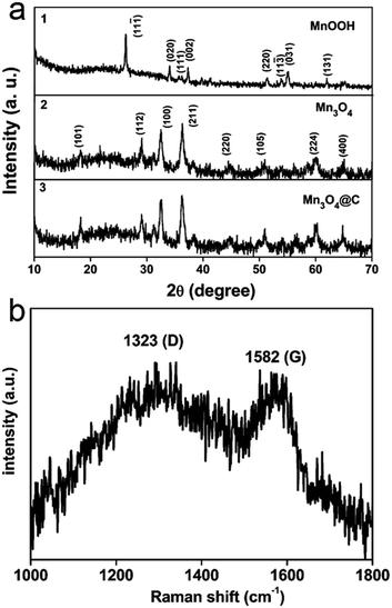 | ||
| Fig. 1 XRD patterns of (a-1) MnOOH nanorods, (a-2) Mn3O4 nanorods and (a-3) Mn3O4@C after carbon coating. (b) Raman spectrum of the Mn3O4@C composite. | ||
Fig. 2 shows the morphology and nanostructure of the MnOOH precursor, Mn3O4 nanorods and Mn3O4@C nanorods. The typical SEM image shows MnOOH nanorods with a length of 3–10 μm and a diameter of 50–80 nm (Fig. 2a). After the MnOOH nanorods were calcined under an Ar atmosphere, Mn3O4 nanorods were obtained and the one dimensional structure was very well maintained (Fig. 2b). Fig. 2c shows a panoramic view of the Mn3O4@C nanorods when the MnOOH precursor was annealed in a C2H2/Ar gas flow. It is noted that the one dimensional structures have almost no change. Fig. 2d shows a typical TEM image of a single Mn3O4@C nanorod, which indicates that the carbon coating layer is uniform. Furthermore, the HRTEM image (Fig. 2e) of the enlarged area demonstrates that Mn3O4@C exhibits a carbon layer with the thickness of ∼3 nm as well as a porous structure, which would facilitate the material to obtain a good electrochemical performance. The HRTEM image (Fig. 2f) shows lattice fringes with the spacing of 0.49 nm, which corresponds to the (101) planes of Mn3O4.
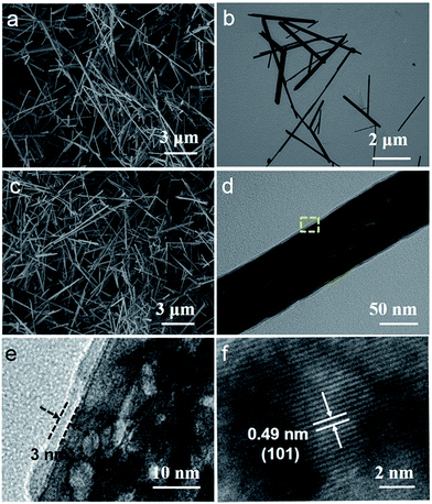 | ||
| Fig. 2 (a) SEM image of MnOOH nanorods, (b) TEM image of Mn3O4 nanorods, (c) SEM image, (d) TEM image and (e and f) HRTEM images of Mn3O4@C nanorods. | ||
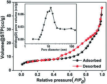
The porous structure in the Mn3O4@C nanorods was characterized using Brunauer–Emmett–Teller (BET) measurements and the results are shown in Fig. 3. The isotherms are characteristic of a type IV with a type H1 hysteresis loop, confirming the mesoporous structure in the Mn3O4@C nanorods.22 The BET surface area is calculated to be 26.5 m2 g−1 and the pore volume is 0.07 cm3 g−1. Furthermore, the most probable distribution of pore size is approximately 10.6 nm according to the Barrett–Joyner–Halenda (BJH) method, which is consistent with the HRTEM images (Fig. 2e).
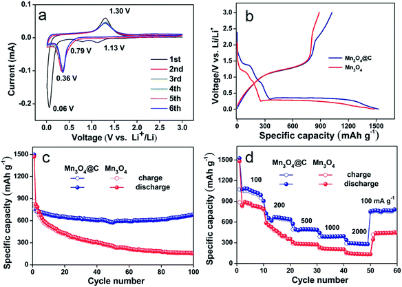
The Mn3O4@C nanorods as an anode material were tested by cyclic voltammetry, as shown in Fig. 4a. The two cathodic peaks at 1.13 V and 0.06 V in the first cycle, could be ascribed to the reduction of Mn3O4 to MnO and MnO to metallic Mn.8 The peak centered at 0.79 V can be assigned to the irreversible decomposition of the liquid electrolyte, which forms a solid electrolyte interface (SEI) layer on the electrode surface.23 In the subsequent anodic sweep, the peak at 1.30 V is due to the oxidation of Mn to Mn2+.8 After the first cycle, the cathodic peak shift to 0.36 V corresponds to the reduction of Mn2+ to Mn, which is due to the structure rearrangements caused by the formation of metals and Li2O.24 Furthermore, the oxidation peak has almost no change. From the second cycle, the subsequent cycles are mostly overlapped very well, indicating the good reversibility of the Mn3O4@C electrodes.
Fig. 4b displays the first discharge–charge curves of the electrodes based on the Mn3O4 and Mn3O4@C nanorods at a current density of 500 mA g−1 using Li metal as the reference and counter electrode. The initial discharge capacities of Mn3O4 and Mn3O4@C are 1481.9 and 1525.1 mA h g−1. The extra capacities above the theoretical capacities may be due to interfacial storage, lithium insertion into acetylene black and formation of the SEI film.25–27 However, Mn3O4@C exhibits a lower initial irreversible capacity loss of 29% compared to 40% for the Mn3O4 nanorods. The large irreversible capacity loss may be attributed to the electrolyte decomposition forming an SEI layer and part of the irreversible reaction.23 Furthermore, the improved coulombic efficiency of the Mn3O4@C nanorods can be due to the good conductivity as well as structure protection of the carbon layer.16
Fig. 4c shows the cycling performance of Mn3O4 and the Mn3O4@C nanorods at a current density of 500 mA g−1 in the range of 0.01–3 V. The Mn3O4@C nanorods deliver a reversible capacity of 765 mA h g−1 after 100 cycles and show relative cyclic stability, which is considerably higher than the pure Mn3O4 nanorods (145 mA h g−1 after 100 cycles). In addition, the data is also considerably higher than those of Mn3O4 composites such as single crystalline Mn3O4 nano-octahedra (500 mA h g−1 after 50 cycles at 50 mA g−1),7 carbon coated Mn3O4 nanorods (473 mA h g−1 after 50 cycles at 40 mA g−1),17 Mn3O4 anchored on graphite nanosheets (437 mA h g−1 after 50 cycles at 200 mA g−1),18 and Mn3O4/graphene nanocomposites (500 mA h g−1 after 40 cycles at 60 mA g−1).19 Furthermore, the high capacity of the Mn3O4@C nanorods is considerably higher than other TMOs.28
In addition to their high capacity and good cycling stability, the remarkable rate performance of the Mn3O4@C nanorods is also achieved at different current densities (Fig. 4d). The Mn3O4@C nanorods exhibit the reversible capacities of 1020, 701, 520, 410 and 380 mA h g−1 at the corresponding current densities of 100, 200, 500, 1000, 2000 mA g−1. Interestingly, as the current density goes back to 100 mA g−1, the specific capacity of the Mn3O4@C nanorods returns to 808 mA h g−1, indicating the structure stability and good rate performance. The rate performance is considerably better than the pure Mn3O4 nanorods, which only exhibits 50 mA h g−1 at the current density of 2000 mA g−1.
The improved cycling performance and good rate performance of the Mn3O4@C nanorods may be partly attributed to their one dimensional porous structure, which could reduce the diffusion path of electrons and ions.13 Furthermore, the porous structure along with the one dimensional peculiarity can accommodate the mechanical strain that is induced by the volume change during repeated Li+ insertion/extraction.15 To further clarify the better electrochemical performance of Mn3O4@C, the electrochemical impedance spectra of Mn3O4@C and Mn3O4 are demonstrated in terms of Nyquist plots, as shown in Fig. 5. The sloping line in the low frequency region refers to the mass transfer of Li ions and the semicircle in the high frequency region is ascribed to the charge transfer process in each plot.29 The charge transfer resistance of the Mn3O4@C nanorods is considerably smaller than the pure Mn3O4 nanorods after carbon coating, confirming their superior electronic conductivity as well as fast Li-ion diffusion. Hence, the uniform carbon coating and unique structure contribute greatly to the high capacity and superior cycling stability of the Mn3O4@C nanorods.
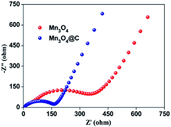 | ||
| Fig. 5 Nyquist plots for the electrodes based on Mn3O4@C and Mn3O4 at the delithiated state of 2.8 V after 5 cycles. | ||
Conclusion
In summary, Mn3O4@C core–shell nanorods were synthesized by calcining MnOOH nanorods under an acetylene reducing atmosphere at 350 °C for 5 h. The obtained Mn3O4@C nanorods with the carbon layer of ∼3 nm were characterized using XRD patterns, Raman spectra, BET measurements, and the TEM and HRTEM techniques. They present a porous property with the specific area of 26.5 m2 g−1 and the distribution of the pore size is ∼10.6 nm. When tested as anodes for LIBs, they deliver the specific capacity of 765 mA h g−1 after 100 cycles at the current density of 500 mA g−1. The one-dimensional shaped porous structure using a carbon coating may pave a new way to improve the electrochemical performance of electrode materials.Acknowledgements
This work was supported by the 973 Project of China (no. 2011CB935901), the National Nature Science Foundation of China (no. 91022033, 51172076 and 21471090), Shandong Provincial Natural Science Foundation for Distinguished Young Scholar (JQ201205), and new-faculty start-up funding in Shandong University.Notes and references
- M. Armand and J. M. Tarascon, Nature, 2008, 458, 652 CrossRef PubMed.
- Y. Idota, T. Kubota, A. Matsufuji, Y. Maekawa and T. Miyasaka, Science, 1997, 276, 1395 CrossRef CAS.
- P. Poizot, S. Laruelle, S. Grugeon, L. Dupont and J. M. Tarascon, Nature, 2000, 407, 496 CrossRef CAS PubMed.
- Z. Xing, Z. C. Ju, J. Yang, H. Y. Xu and Y. T. Qian, Nano Res., 2012, 5, 477 CrossRef CAS.
- Z. C. Bai, N. Fan, Z. C. Ju, C. L. Guo, Y. T. Qian, B. Tang and S. L. Xiong, J. Mater. Chem. A, 2013, 1, 10985 CAS.
- J. Gao, M. A. Lowe and H. D. Abruña, Chem. Mater., 2011, 23, 3223 CrossRef CAS.
- S. Z. Huang, J. Jin, Y. Cai, Y. Li, H. Y. Tan, H. E. Wang, G. V. Tendeloo and B. L. Su, Nanoscale, 2014, 6, 6819 RSC.
- Z. C. Bai, X. Y. Zhang, Y. W. Zhang, C. L. Guo and B. Tang, J. Mater. Chem. A, 2014, 2, 16755 CAS.
- G. Q. Jian, Y. H. Xu, L. C. Lai, C. S. Wang and M. R. Zachariah, J. Mater. Chem. A, 2014, 2, 4627 CAS.
- N. N. Wang, J. Yue, L. Chen, Y. T. Qian and J. Yang, ACS Appl. Mater. Interfaces DOI:10.1021/acsami.5b01208.
- A. Ponrouch, P. L. Taberna, P. Simon and M. R. Palacin, Electrochim. Acta, 2012, 61, 13 CrossRef CAS PubMed.
- Z. C. Bai, N. Fan, C. H. Sun, Z. C. Ju, C. L. Guo, J. Yang and Y. T. Qian, Nanoscale, 2013, 5, 2442 RSC.
- J. Y. Huang, L. Zhong, C. M. Wang, J. P. Sullivan, W. Xu, L. Q. Zhang, S. X. Mao, N. S. Hudak, X. H. Liu, A. Subramanian, H. Y. Fan, L. Qi, A. Kushima and J. Li, Science, 2010, 330, 1515 CrossRef CAS PubMed.
- N. N. Wang, L. Chen, X. J. Ma, J. Yue, F. E. Niu, H. Y. Xu, J. Yang and Y. T. Qian, J. Mater. Chem. A, 2014, 2, 16847 CAS.
- A. Vu, Y. Q. Qian and A. Stein, Adv. Energy Mater., 2012, 2, 1056 CrossRef CAS PubMed.
- H. Q. Li and H. S. Zhou, Chem. Commun., 2012, 48, 1201 RSC.
- C. B. Wang, L. W. Yin, D. Xiang and Y. X. Qi, ACS Appl. Mater. Interfaces, 2012, 4, 1636 CAS.
- S. Y. Liu, J. Xie, Y. X. Zheng, G. S. Cao, T. J. Zhu and X. B. Zhao, Electrochim. Acta, 2012, 66, 271 CrossRef CAS PubMed.
- I. Nam, N. D. Kim, G. P. Kim, J. S. Park and J. H. Yi, J. Power Sources, 2013, 244, 56 CrossRef CAS PubMed.
- Z. C. Bai, B. Sun, N. Fan, Z. C. Ju, M. H. Li, L. Q. Xu and Y. T. Qian, Chem.–Eur. J., 2012, 18, 5319–5324 CrossRef CAS PubMed.
- A. Ferrari and J. Robertson, Phys. Rev. B: Condens. Matter Mater. Phys., 2000, 61, 14095 CrossRef CAS.
- M. Kruk and M. Jaroniec, Chem. Mater., 2001, 13, 3169 CrossRef CAS.
- S. Grugeon, S. Laruelle, R. Herrera-Urbina, L. Dupont, P. Poizot and J. M. Tarascon, J. Electrochem. Soc., 2001, 148, A285 CrossRef CAS PubMed.
- G. Binotto, D. Larcher, A. S. Prakash, R. H-Urbina, M. S. Hegde and J. M. Tarascon, Chem. Mater., 2007, 19, 3032–3040 CrossRef CAS.
- J. S. Xu and Y. J. Zhu, ACS Appl. Mater. Interfaces, 2012, 4, 4752 CAS.
- P. Balaya, H. Li, L. Kienle and J. Maier, Adv. Funct. Mater., 2003, 13, 621 CrossRef CAS PubMed.
- Y. Zhao, Y. Huang, X. Sun, H. J. Huang, K. Wang, M. Zong and Q. F. Wang, Electrochim. Acta, 2014, 120, 128 CrossRef CAS PubMed.
- E. Zhang, Z. Xing, J. Wang, Z. C. Ju and Y. T. Qian, RSC Adv., 2012, 2, 6748 RSC.
- J. S. Luo, X. H. Xia, Y. S. Luo, C. Guan, J. L. Liu, X. Y. Qi, C. F. Ng, T. Y. H. Zhang and H. J. Fan, Adv. Energy Mater., 2013, 3, 737 CrossRef CAS PubMed.
| This journal is © The Royal Society of Chemistry 2015 |

