High-performance microwave absorption of flexible nanocomposites based on flower-like Co superstructures and polyvinylidene fluoride

Xiao-Juan Zhang a, Guo-Cheng Lvb, Guang-Sheng Wang*a, Tian-Yu Baia, Jia-Kang Qua, Xiao-Fang Liu*c and Peng-Gang Yin*a
aKey Laboratory of Bio-Inspired Smart Interfacial Science and Technology of Ministry of Education, School of Chemistry and Environment, Beihang University, Beijing 100191, PR China. E-mail: wanggsh@buaa.edu.cn
bSchool of Material Sciences and Technology, China University of Geosciences, Beijing, 100083, China
cSchool of Materials Science and Engineering, Beihang University, Beijing 100191, China

Received 13th April 2015 , Accepted 17th June 2015

First published on 17th June 2015


Abstract

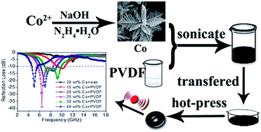
Flower-like Co superstructures were synthesized via a facile hydrothermal process at low temperature; then the flexible Co/PVDF nanocomposites were prepared by combining the Co nanocrystal with a polyvinylidene fluoride (PVDF) matrix. The Co/PVDF hybrids exhibit distinct microwave absorption properties in the range of 2–18 GHz. With filler loading of 25 wt%, the minimum reflection loss reaches −38.9 dB at 6.4 GHz as the thickness is 2.5 mm. The frequency bandwidth less than −10 dB covers from 4.64 to 10.56 GHz by adjusting the weight content from 15 wt% to 40 wt%. The possible microwave absorbing mechanism has been also discussed in detail.
Introduction

In recent years, damage by electromagnetic (EM) radiation has received more and more attention with the increasing development of information technology such as satellite communication, radar systems, local area networks and personal digital assistants.1–3 Thus, high-performance microwave absorption material with good absorbing ability is extensively in demand to eliminate harmful EM waves and convert EM energy into thermal energy through dielectric loss or magnetic loss resulting from efficient complementarities between the relative permittivity and permeability.4,5 High-efficiency microwave absorbers exhibit light weight, tiny thickness, wide absorption frequency range and strong EM wave absorption characteristics simultaneously.6,7

The microwave absorption properties of ferromagnetic metal particles with submicron or nanometer scales have attracted a considerable attention due to their distinct physical and chemical properties.8,9 The intrinsic electromagnetic characteristics of ferromagnetic metallic microparticles mainly include element component, microstructure, particle morphology and size.10 Many researchers have investigated the wave absorption properties of ferromagnetic metal particles, such as Fe3O4,11 FeCo,12 Ni/Co,10 MnFe2O4,13 α-Fe2O3@CoFe2O4 (ref. 14) and so on. In addition, to achieve better absorbing performance, the composites of ferromagnetic metallic microparticles dispersing into insulating matrix have been widely studied. For example, Liu et al.15 synthesized GN/PEDOT/Fe3O4 nanocomposites and investigated their microwave absorption properties. The minimum reflection loss of the nanocomposites was up to −56.5 dB at 8.9 GHz and the absorption bandwidths exceeding −10 dB were 3 GHz with a thickness of 2.9 mm. Wei et al.16 reported a simple and effective method for preparing Fe3O4@polyaniline/polyazomethine/polyetheretherketone ternary-hybrid membranes which exhibited significant microwave-absorbing properties with a minimum reflection loss about −18 dB at 14 GHz.

As a typical ferromagnetic material, cobalt nanomaterials have received widespread attention for their extensive application in the fields of catalysis;17 medical diagnosis18 and high-density data storage.19 Moreover, metallic cobalt possess three crystal structures (the hexagonal close packed (hcp) α-phase, the face centered cubic (fcc) β-phase and a primitive (or pseudo-) cubic ε-phase)20 and various morphologies, such as hollow porous cobalt spheres;21 cobalt nanorods;22 cobalt nanoplatelets9 and cobalt nanowires.23 To date, the electromagnetic wave absorption property of cobalt particles have been extensively studied. Zhang et al.24 synthesized carbon-encapsulated cobalt nanoparticles (Co(C)) with a diameter of 10–50 nm and reported the wave absorption property of Co(C)/paraffin composite. It was found that the minimum calculated reflection loss (RL) could reach −52 dB at 7.54 GHz with 50 wt% Co(C) at a thickness of 3 mm. Liu et al.25 investigated the hierarchical architecture effect on the microwave absorption properties of cobalt composites. The results indicated that a composite consisting of dendritic filler showed an improved electromagnetic absorption performance in low frequencies compared with the conventional spherical filler.

In this paper, we used a simple hydrothermal approach to prepare flower-like Co superstructures without any surfactants and complex precursors. Then combined them with flexible polymer PVDF firstly and investigated their microwave absorption properties. PVDF is a typical dielectric material, and its simple chemical structure (–CH2–CF2–) gives the molecular chain both high flexibility and some stereochemical constraint that will be beneficial to EM wave absorption property and increase their practical application immensely.

Experimental

All chemical reagents were purchased from Lanyi Chemical Company. And all were of analytical grade and used without further purification.

Preparation of flower-like Co superstructures

In a typical synthesis, 0.2 M CoCl2·6H2O and 1 M sodium hydroxide (NaOH) were dissolved in 50 mL distilled water. Subsequently, 15 mL 80% hydrazine hydrate (N2H4·H2O) was added to the solution. Then the homogeneous suspension was transferred into a Teflon-lined stainless steel autoclave (100 mL). After reacting in 120 °C for 4 h, the solution was cooled to room temperature. The resultant gray product was washed several times with distilled water and absolute ethanol and finally dried at 50 °C for 12 h for further characterization.

Preparation of Co/PVDF composite

The composites were prepared by mixing the flower-like Co with the polymer PVDF using a simple blending and hot-molding procedure. PVDF was dissolved in N,N-dimethylformamide (DMF) at room temperature. After the solution became transparent, various contents of Co powder were added and sonicated for several minutes, then poured them into glassy Petridishes after mixing the dispersion uniformly at room temperature. After that, it was dried in the oven at 100 °C. The dried mixture was collapsed and compressed into wafers for 15 min at 200 °C under 6 MPa (prepressed for 5 min at the same temperature, released the press for a while, and then repressed for 20 min, followed by cooling to room temperature under the same pressure).

Characterization

XRD analyses were carried out on an X-ray diffractometer (D/MAX-1200, Rigaku Denki Co. Ltd., Japan). The XRD patterns with Cu Ka radiation (λ = 1.5406 Å) at 40 kV and 40 mA were recorded in the range of 2θ = 10°–90°. Scanning electron microscope (SEM) images were achieved by a FEI Quanta 250 field-emission gun environmental scanning electron microscope at 15 kV with the samples obtained from the thick suspension dropping on the silicon slice. Transmission Electron Microscopy (TEM) images were obtained using a JEM-2100F transmission electron microscope operated at 200 kV. The magnetic properties were carried out on a Quantum Design superconducting quantum interference device (SQUID) magnetometer (MPMS-7) at 300 K.

EM absorption measurement

The composites used for EM absorption measurement were prepared by mixing the products with wax and PVDF in different mass percentages, respectively. The mixtures were then pressed into cylindrical-shaped samples (Φout = 7.00 mm and Φin = 3.04 mm). The complex permittivity and permeability values were measured in the 2–18 GHz range with coaxial wire method by an Agilent N5230C PNA-L Network Analyzer.

Results and discussion

Fig. 1 shows the typical XRD patterns of flower-like Co superstructure and Co/PVDF membrane. From the XRD pattern of Co powder, it can be seen that all the diffraction peaks are readily indexed to the structure of hexagonal phase (JCPDS no. 05-0727) and no other characteristic peaks for impurities are observed. The narrow sharp peaks indicate that the samples with high crystallinity. As shown in Fig. 1b and c, the broad peaks around 21° represent the existence of PVDF.13 In addition, all the diffraction peaks of Co exist in Co/PVDF membrane, indicating that the Co powder disperse in PVDF effectively.
image file: c5ra06597f-f1.tif
Fig. 1 XRD patterns of: (a) Co; (b) 10 wt% Co/PVDF membrane; (c) 30 wt% Co/PVDF membrane.

The morphology and crystallinity of flower-like Co structure were examined by SEM, TEM, SAED and HRTEM. The SEM images shown in Fig. 2a and b indicate that the synthesized products consist of flower-like architectures which assembled by leaf-like flakes. The average diameter of Co nanocrystal is about in the range of 5–7 μm. Each leaf-like flake radiates from a long central main branch and consists by a series of parallel secondary branches that emerge at about 60 angles with respect to the main branch. (Fig. 2a–c) The selected area electron diffraction (SAED) pattern (Fig. 2d) corresponding to the circled area in Fig. 2c shows perfect single crystal nature of flower-like Co. Besides, the ordered lattice fringes are clearly observed from a high-resolution TEM image in Fig. 2e. The distances between the neighboring lattice fringes are approximately 0.19 nm and 0.22 nm, relative to the (101) and (100) plane respectively. The result is well accordance with that of XRD. As observed in Fig. 2f, the cross-sectional FESEM image of Co/PVDF membrane shows that flower-like Co disperse in PVDF uniformly and remain the special hierarchical structure well. The elemental maps of Co, C and F in Fig. 3 further indicate that the flower-like Co mix well with PVDF.


image file: c5ra06597f-f2.tif
Fig. 2 (a and b) SEM; (c) TEM images; (d) SAED pattern; (e) high-resolution TEM image of flower-like Co and (f) cross-sectional FESEM image of Co/PVDF membrane.

image file: c5ra06597f-f3.tif
Fig. 3 FESEM image of the fracture section of Co/PVDF membrane and corresponding elemental mapping images of Co, C and F.

The magnetic property is very important to investigate the electromagnetic wave absorption properties. The field dependence of magnetization of the prepared Co sample was measured at room temperature. Typical hysteresis loop shown in Fig. 4 indicates the ferromagnetic behavior of the flower-like Co. The saturation magnetization (Ms), remanent magnetization (Mr), and coercivity (Hc) values of the sample are 138.0 emu g−1, 12.9 emu g−1 and 240.0 Oe, respectively. The difference of the pinned surface magnetic moments in overall magnetization results in the Ms value of flower-like Co is much smaller than that of Co microsphere (169.5 emu g−1). However, the coercivity (Hc) value of flower-like Co is larger due to these cobalt particles are in micron scale. The larger Hc value makes them possess more magnetocrystalline anisotropy energy which will be in favor of the enhancement of microwave absorption performance.26,27


image file: c5ra06597f-f4.tif
Fig. 4 Hysteresis loops of flower-like Co nanocrystal at room temperature.

To study the electromagnetic wave absorption properties of flower-like Co nanocrystal and Co/PVDF nanocomposites, various contents of the samples were mixed with wax or PVDF to form composites and press the mixture into a cylindrical shaped compact (Φout = 7.00 mm and Φin = 3.04 mm) by a simple hot press method. Fig. 5a and c show the frequency dependence of real permittivity and permeability for different materials, while the imaginary permittivity and imaginary permeability can be observed in Fig. S1. The real permittivity (ε′) and real permeability (μ′) represent the storage ability for electromagnetic energy, and the imaginary permittivity (ε′′) and imaginary permeability (μ′′) are an expression for the dissipation of energy and magnetic loss, respectively.28 The dielectric and magnetic loss, a ratio of the imaginary value to real value, is plotted in Fig. 5b and d. As shown in Fig. 5, the dielectric constants improve significantly after combined with PVDF. The tangent loss (tan[thin space (1/6-em)]δe = ε′′/ε′) exhibits more resonant peaks with increasing weight loading of Co. Furthermore, the ferromagnetism of Co leads to an obvious improvement of permeability for all samples compared with pure PVDF. The error bars of measured real and imaginary part of permittivity and permeability values for two typical composites were also shown in Fig. S3.


image file: c5ra06597f-f5.tif
Fig. 5 Frequency dependence on (a) real part of the complex permittivity; (b) dielectric loss; (c) real part of the complex permeability and (d) magnetic loss of samples.

According to the values of dielectric loss and magnetic loss, it can be observed that the dielectric loss values of these composites are higher than their magnetic loss values except for that of Co/wax nanocomposite. So the main loss mechanism for them is dielectric loss rather than magnetic loss. The causes for dielectric loss mainly include electronic dipole polarization and interfacial polarization. Due to PVDF is a strong dipole material, therefore, the existence of electrophilic fluorine in the molecular structure of PVDF may cause electronic dipole polarization effectively. On the other hand, interface polarization generated from two neighboring phases that are different from with each other in dielectric constant, conductivity, or both, at testing frequencies.25 For Co/PVDF nanocomposites, the hierarchical structure of Co makes it form more interface with PVDF easily.

Due to Co nanocrystal is a typical kind of magnetic material, then according to the research findings of van Der Zaag's,29 the magnetic loss mainly includes: eddy current loss, hysteresis loss, ferromagnetic resonance loss and intragranular domain wall loss. The hysteresis loss is negligible in weak field and the domain wall loss commonly occurs at MHz frequency.30 For Co/PVDF composites, the natural resonance and eddy current effect may be responsible for the microwave attenuation in the range of 2–18 GHz. The natural resonance for Co/PVDF nanocomposite is resulted from the presence of resonant permeability peaks. Just as the hysteresis loop curve shown in Fig. 4, there is a reversible rotational magnetization process when magnetic field are applied to flower-like Co nanocrystal. The reversible rotation of the magnetization vector is of benefit to improve permeability in high frequency.31 Furthermore, in order to study the influence of eddy current effect on EM wave absorption property in high frequency range, C0f curve for 25 wt% Co/PVDF composites is showed in Fig. 6. The eddy current loss can be evaluated by following equation:

 
μ′′ ≈ 2πμ2(μ′)2σd2f/3 (1)
where σ (S cm−1) is the electrical conductivity and μ0 (H m−1) is the permeability in vacuum. If the magnetic loss results from the eddy current loss effect, the values of C0 (C0 = μ′′(μ′) − 2f − 1) are constant when the frequency varies. As shown in Fig. 6, it can be observed that the value of C0 fluctuates in the range of 2–18 GHz, which indicates that the eddy current loss effect has no significant influence on microwave energy dissipation.


image file: c5ra06597f-f6.tif
Fig. 6 The C0f curve of 25 wt% Co/PVDF composites.

Except for dielectric loss and magnetic loss mechanism, as our previous research,32–34 the synergetic effect between Co and PVDF could also enhance the wave absorption abilities. And the difference in complex permittivity between Co and PVDF would generate interface scattering, leading to more wave absorption.35

To measure the EM wave absorption property, the reflection loss (RL) of the electromagnetic radiation under the normal incidence of the electromagnetic field was calculated. According to the transmission line theory, reflection loss (RL) usually can be calculated by following equation:36

 
image file: c5ra06597f-t1.tif(2)
where Zin is the input characteristic impedance, which can be expressed as:37
 
image file: c5ra06597f-t2.tif(3)
where, εr and μr are the complex permittivity and permeability of the composite absorber, respectively; f is the frequency; d is the thickness of the absorber, and c is the velocity of light in free space.

Fig. 7 shows calculated theoretical RLs of 30 wt% Co/wax nanocomposite and Co/PVDF composites with different loadings (15, 20, 25, 30 and 40 wt%) at a thickness of 2.5 mm in the frequency range of 2–18 GHz. It can be observed that RL values are much higher after combined with PVDF. The minimum reflection loss reaches −38.9 dB at 6.4 GHz with a loading of only 25 wt% as the thickness is 2.5 mm. And the frequency bandwidth less than −10 dB covers from 4.64 to 10.56 GHz by adjusting the weight content from 15 wt% to 40 wt%. Compared with the other reported references (as shown in Table S1), our synthesized Co/PVDF nanocomposites show enhanced wave absorption property with low weight content and broad effective frequency bandwidth. Except for this, the Co/PVDF membrane is still as flexible as the pure PVDF except for the enhanced wave absorption properties, and can be cut into any different shapes as you want (Fig. S2). Fig. 8a–f show the three-dimensional presentations of calculated theoretical RLs of different samples with different thickness (2–5 mm) in the range of 2–18 GHz. It is concluded that the EM wave absorption ability of Co/PVDF nanocomposite at different frequency can be tuned by controlling the thickness of the absorbers.


image file: c5ra06597f-f7.tif
Fig. 7 Microwave RL curves of the composites with a thickness of 2.5 mm in the frequency range of 2–18 GHz.

image file: c5ra06597f-f8.tif
Fig. 8 Three-dimensional representations of the RL of (a) Co/wax with a loading of 30 wt%; Co/PVDF composites with a loading of (b) 15 wt%; (c) 20 wt%; (d) 25 wt%; (e) 30 wt%; (f) 40 wt%.

Conclusions

Flower-like Co superstructures and Co/PVDF nanocomposites have been fabricated in large-scale by a simple method. The results indicate that the Co/PVDF composites possess excellent wave absorption properties. With a filler loading of 25 wt%, the minimum reflection loss reaches −38.9 dB at 6.4 GHz at a thickness of 2.5 mm. Furthermore, the frequency bandwidth less than −10 dB covers from 4.64 to 10.56 GHz by adjusting the weight content from 15 wt% to 40 wt%. The main microwave absorbing mechanism for Co/PVDF composite is the combination of dielectric loss, magnetic loss and the synergetic effect between Co and PVDF. Thus, it turns out that the composites are promising microwave absorbing materials.

Acknowledgements

This work was supported by the National Natural Science Foundation of China (no. 51472012) and the Fundamental Research Funds for the Central Universities.

Notes and references

  1. Y. Zhang, Y. Huang, T. Zhang, H. Chang, P. Xiao, H. Chen, Z. Huang and Y. Chen, Adv. Mater., 2015, 27, 2049–2053 CrossRef CAS PubMed.
  2. G. Pan, J. Zhu, S. Ma, G. Sun and X. Yang, ACS Appl. Mater. Interfaces, 2013, 5, 12716–12724 CAS.
  3. W. Zhu, L. Wang, R. Zhao, J. Ren, G. Lu and Y. Wang, Nanoscale, 2011, 3, 2862–2864 RSC.
  4. J. Liu, R. Che, H. Chen, F. Zhang, F. Xia, Q. Wu and M. Wang, Small, 2012, 8, 1214–1221 CrossRef CAS PubMed.
  5. G. Wang, Z. Gao, S. Tang, C. Chen, F. Duan, S. Zhao, S. Lin, Y. Feng, L. Zhou and Y. Qin, ACS Nano, 2012, 6, 11009–11017 CAS.
  6. J. Guo, H. Wu, X. Liao and B. Shi, J. Phys. Chem. C, 2011, 115, 23688–23694 CAS.
  7. L. Kong, X. Yin, Y. Zhang, X. Yuan, Q. Li, F. Ye, L. Cheng and L. Zhang, J. Phys. Chem. C, 2013, 117, 19701–19711 CAS.
  8. J. T. Jiang, X. J. Wei, C. Y. Xu, Z. X. Zhou and L. Zhen, J. Magn. Magn. Mater., 2013, 334, 111–118 CrossRef CAS PubMed.
  9. J. Li, J. Huang, Y. Qin and F. Ma, Mater. Sci. Eng., B, 2007, 138, 199–204 CrossRef CAS PubMed.
  10. S. J. Yan, S. L. Dai, H. Y. Ding, Z. Y. Wang and D. B. Liu, J. Magn. Magn. Mater., 2014, 358–359, 170–176 CrossRef CAS PubMed.
  11. C. L. Zhu, M. L. Zhang, Y. J. Qiao, G. Xiao, F. Zhang and Y. J. Chen, J. Phys. Chem. C, 2010, 114, 16229–16235 CAS.
  12. Z. Han, D. Li, H. Wang, X. G. Liu, J. Li, D. Y. Geng and Z. D. Zhang, Appl. Phys. Lett., 2009, 95, 023114 CrossRef PubMed.
  13. X. J. Zhang, G. S. Wang, W. Q. Cao, Y. Z. Wei, J. F. Liang, L. Guo and M. S. Cao, ACS Appl. Mater. Interfaces, 2014, 6, 7471–7478 CAS.
  14. H. Lv, X. Liang, Y. Cheng, H. Zhang, D. Tang, B. Zhang, G. Ji and Y. Du, ACS Appl. Mater. Interfaces, 2015, 7, 4744–4750 CAS.
  15. P. Liu, Y. Huang and X. Zhang, J. Alloys Compd., 2014, 617, 511–517 CrossRef CAS PubMed.
  16. W. Wei, X. Yue, Y. Zhou, Y. Wang, Z. Chen, M. Zhu, J. Fang and Z. Jiang, RSC Adv., 2014, 4, 11159–11167 RSC.
  17. Z. Y. Wu, P. Chen, Q. S. Wu, L. F. Yang, Z. Pan and Q. Wang, Nano Energy, 2014, 8, 118–125 CrossRef CAS PubMed.
  18. R. H. Christenson, S. H. Duh, W. R. Sanhai, A. H. B. Wu, V. Holtman, P. Painter, E. Branham, F. S. Apple, M. Murakami and D. L. Morris, Clin. Chem., 2001, 47, 464–470 CAS.
  19. N. Liakakos, T. Blon, C. Achkar, V. Vilar, B. Cormary, R. P. Tan, O. Benamara, G. Chaboussant, F. Ott, B. Warot-Fonrose, E. Snoeck, B. Chaudret, K. Soulantica and M. Respaud, Nano Lett., 2014, 14, 3481–3486 CrossRef CAS PubMed.
  20. Q. He, T. Yuan, Z. Luo, N. Haldolaarachchige, D. P. Young, S. Wei and Z. Guo, Chem. Commun., 2013, 49, 2679–2681 RSC.
  21. C. He, S. Qiu, X. Wang, J. Liu, L. Luan, W. Liu, M. Itoh and K. i. Machida, J. Mater. Chem., 2012, 22, 22160–22166 RSC.
  22. W. Zhou, Y. Zhou, L. Yang, J. Huang, Y. Ke, K. Zhou, L. Li and S. Chen, J. Mater. Chem. A, 2015, 3, 1915–1919 CAS.
  23. L. Yuan, S. Meng, Y. Shi, Y. Zhang, Z. Yue and L. Li, Appl. Phys. Lett., 2014, 105, 182407 CrossRef PubMed.
  24. D. Zhang, F. Xu, J. Lin, Z. Yang and M. Zhang, Carbon, 2014, 80, 103–111 CrossRef CAS PubMed.
  25. T. Liu, P. H. Zhou, J. L. Xie and L. J. Deng, J. Appl. Phys., 2011, 110, 033918 CrossRef PubMed.
  26. C. Wang, X. Han, X. Zhang, S. Hu, T. Zhang, J. Wang, Y. Du, X. Wang and P. Xu, J. Phys. Chem. C, 2010, 114, 14826–14830 CAS.
  27. S. Wen, Y. Liu, X. Zhao, J. Cheng and H. Li, Powder Technol., 2014, 264, 128–132 CrossRef CAS PubMed.
  28. W. Zhou, X. Hu, X. Bai, S. Zhou, C. Sun, J. Yan and P. Chen, ACS Appl. Mater. Interfaces, 2011, 3, 3839–3845 CAS.
  29. P. J. van der Zaag, J. Magn. Magn. Mater., 1999, 196–197, 315–319 CrossRef CAS.
  30. M. Wu, Y. D. Zhang, S. Hui, T. D. Xiao, S. Ge, W. A. Hines, J. I. Budnick and G. W. Taylor, Appl. Phys. Lett., 2002, 80, 4404–4406 CrossRef CAS PubMed.
  31. X. G. Liu, B. Li, D. Y. Geng, W. B. Cui, F. Yang, Z. G. Xie, D. J. Kang and Z. D. Zhang, Carbon, 2009, 47, 470–474 CrossRef CAS PubMed.
  32. G. S. Wang, X. J. Zhang, Y. Z. Wei, S. He, L. Guo and M. S. Cao, J. Mater. Chem. A, 2013, 1, 7031–7036 CAS.
  33. S. He, G. S. Wang, C. Lu, J. Liu, B. Wen, H. Liu, L. Guo and M. S. Cao, J. Mater. Chem. A, 2013, 1, 4685–4692 CAS.
  34. X. J. Zhang, G. S. Wang, Y. Z. Wei, L. Guo and M. S. Cao, J. Mater. Chem. A, 2013, 1, 12115–12122 CAS.
  35. M. Fu, Q. Jiao and Y. Zhao, J. Mater. Chem. A, 2013, 1, 5577–5586 CAS.
  36. G. S. Wang, L. Z. Nie and S. H. Yu, RSC Adv., 2012, 2, 6216–6221 RSC.
  37. M. S. Cao, X. L. Shi, X. Y. Fang, H. B. Jin, Z. L. Hou, W. Zhou and Y. J. Chen, Appl. Phys. Lett., 2007, 91, 203110 CrossRef PubMed.

Footnotes

Electronic supplementary information (ESI) available. See DOI: 10.1039/c5ra06597f
Xiao-Juan Zhang and Guo-Cheng Lv are joint first authors.

This journal is © The Royal Society of Chemistry 2015
Click here to see how this site uses Cookies. View our privacy policy here.