Investigation of demulsification efficiency in water-in-crude oil emulsions using dissipative particle dynamics

Xianyu Song*a, Peng Shia, Ming Duanab, Shenwen Fangab and Yongzhang Maa
aCollege of Chemistry and Chemical Engineering, Southwest University of Petroleum, 8 Xindu Avenue, Xindu District, Chengdu, Sichuan 610500, P. R. China. E-mail: swpua124@126.com; Fax: +8602883037346; Tel: +8602883037346
bOil & Gas Field Applied Chemistry Key Laboratory of Sichuan Province, Chengdu, 610500, P. R. China

Received 13th April 2015 , Accepted 16th July 2015

First published on 16th July 2015


Abstract

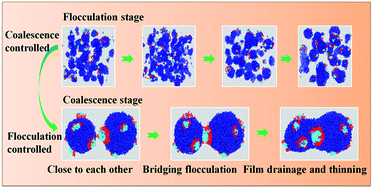
In this study, simulations of dissipative particle dynamics (DPD) were employed to investigate the efficiency of polyether demulsifiers, substituting polyoxypropylene (PPO) hydrophobic blocks for polybutylene oxide (PBO) and polytetrahydrofuran (PTF) in ultra-heavy crude oil emulsions. The simulation results showed that the demulsifiers with polybutylene oxide (PBO) hydrophobic blocks favor high levels of demulsification while the demulsifiers with polyoxypropylene (PPO) hydrophobic blocks exhibit better dehydration rates. The kinetics equation demonstrates that the demulsification process is controlled by the combination of flocculation and coalescence. As time progresses, the rate-controlling process of demulsification changes from coalescence controlled to flocculation controlled. Moreover, high performance demulsifiers which have higher rate constants for coalescence could accelerate the rate of drainage of the film much faster, thereby promoting coalescence. The root mean square end-to-end distance 〈R〉 for demulsifiers continues to grow with time, such that their configurations become more stretched. This results in interface arraying and the demulsifiers build up a continuous open network which leads to a higher possibility of droplet–droplet coalescence. The variation in radial distribution function (RDF) indicates that there is a rather strong and remarkably structured interaction between asphaltenes and demulsifiers, corresponding to the radial distribution range from 10 Å to 50 Å.

1. Introduction

Water-in-oil emulsions formed during oil slicks or petroleum production are known to be stabilized by interfacially active substances that naturally occur in crude oil, such as, asphaltenes, resins, naphthenic acids, and fine solid.1–3 Destabilization of emulsions is an essential step in obtaining water-free oil. There are various methods used to separate crude oil from oil–water emulsions, such as mechanical, electric, and chemical,4 but the addition of chemical demulsifiers is the most widely practiced method.5

Demulsifiers, an amphiphilic and surface-active polymers, can absorb at the water/oil interface and change water/oil interfacial properties, such as, interfacial tension,6 interfacial dilational viscoelasticity,7,8 and interfacial rheological properties.9 Currently, the main focus is on use of non-ionic demulsifiers, especially polyoxypropylene–polyoxyethylene (PPO–PEO) polyether demulsifiers, where the propylene oxide (PO) blocks provide the hydrophobic component of the demulsifiers and the propylene oxide (EO) blocks function as the hydrophilic component.10 By varying the number and arrangement of the ethylene oxide (EO) and propylene oxide (PO) groups, amphiphilic copolymer demulsifiers having different structures and molecular weights were synthesized and widely used in oilfields.11,12 Unfortunately, the higher level of heavy fractions of crude oil usually lead to the formation of highly stable oil–water emulsions.13 Conventional demulsifiers failed to solve the above problem in oilfields. Thus, it remains a challenge to design other highly effective demulsifiers to be used in oilfield stimulation. In this paper, some novel polyether demulsifiers, in which the hydrophobic groups PPO blocks are replaced by poly butylene oxide (PBO), and polytetrahydrofuran (PTF), are designed and discussed in detail.

In the past decades, a large number of theoretical researches had been dedicated to the study of microstructures of amphiphilic copolymers using computer simulations. It is in principle, viable to study the efficiency of the demulsifiers at the atomistic level using molecular dynamics (MD).14 MD can provide specific information regarding the interfacial behavior of demulsifiers without compromising the atomistic details. However, the time scale and length scale accessible to classical MD is too short to allow for observation the efficiency of demulsifiers in the crude oil–water emulsions. Generally, oilfield emulsions have droplet sizes exceeding 0.1 μm and may be larger than 50 μm.15 It is obvious that the demulsification takes place at mesoscopic level. However, by introducing dissipative force and the coup of friction coefficient and noise amplitude, DPD is an excellent method for the simulation of coarse-grained systems over considerable length and time scales up to the mesoscopic level.16

DPD method is a powerful tool for investigating emulsion systems. Lin et al.17 used DPD method to study the microstructures of an emulsion using alternating copolymers as the demulsifiers and also to study the kinetics of emulsion formation. Subsequently, Fan and Striolo18 reported the mechanism of coalescence of droplets in Pickering emulsions. Fraaije et al.19 made use of the DPD method to design the microemulsion process and succeeded in proposing a dependable method of moments for computational microemulsion analysis.

In this paper, demulsification efficiencies of several types of novel polyether demulsifiers, in which the hydrophobic group PPO blocks were replaced by polybutylene oxide (PBO) blocks and polytetrahydrofuran (PTF) blocks, were investigated by dissipative particle dynamics (DPD). Moreover, the dynamics for the demulsification process has been investigated and the demulsification kinetics discuss. Finally, by introducing the root mean square end-to-end distance 〈R〉 and the radial distribution function (RDF), the effect of different hydrophobic blocks on the demulsification efficiency has also been studied. As a result, the coalescence process in the presence of demulsifiers can be better understood.

2. Model and methods

2.1 Dissipative particle dynamics (DPD) simulation technique

The DPD simulation was developed by Hoogerbrugge and Koelman and cast in the present form by Español.16 In DPD simulation, the aggregates of plurality of atoms or molecules are defined as a bead. Every bead's motion equation accords with the Newton's law.
 
image file: c5ra06570d-t1.tif(1)
where ri and vi are denoted as the position vector and velocity of the ith bead.
 
image file: c5ra06570d-t2.tif(2)

The term in brackets are three non-bonded forces acting between each pair of beads: conservative repulsive forces (FCij), representing excluded volume; dissipative forces (FDij), representing viscous drag; random forces (FRij), representing stochastic impulse. The remaining terms are forces due to bonded interactions: springs force (fSi).

Here, conservative forces (FCij), is usually soft repulsive of the form

 
image file: c5ra06570d-t3.tif(3)
where aij is a maximum repulsion between particles i and j, rij, |rij| are the distance and relative distance between them, with the corresponding unit vector [r with combining circumflex]ij which defined as [r with combining circumflex] = (rirj)/|rij|.

The other two forces dissipative forces (FDij), random forces (FRij) are given by

 
image file: c5ra06570d-t4.tif(4)
 
image file: c5ra06570d-t5.tif(5)
where vij defined as vij = vivj, vij is the velocity difference for the two particles, and q is a random number between 0 and 1, ω is the weight function. γ is the friction coefficient and σ is the noise amplitude. The combined effect of these two forces is a thermostat, which conserves momentum and, hence, gives the correct hydrodynamics at sufficient long time and length scales.20

To obey the fluctuation-dissipation theorem, it must have ωD = (ωR)2, and the system temperature will follow from the relation between γ and σ·σ2/ γ−1 = 2kT. The same integration algorithm, weight functions, and parameters as Groot and Warren are utilized throughout paper:16

 
image file: c5ra06570d-t6.tif(6)
where
 
image file: c5ra06570d-t7.tif(7)

Throughout this paper the reduced units are used and rC is the unit of length, kT (the temperature of the thermostat) is the unit of energy, and the mass unit is the mass of a DPD bead. In these units, the dissipative parameter γ = 4.5, the noise parameter σ = 3.0.21

All DPD beads belonging to the same molecule are connected by a loosely bounded spring. By means of this spring force, the molecule's stiffness can be controlled, and the particles can be interconnected to complex topologies. According to Groot's work, the spring force fSj on particle i can be calculated by equation with a spring force constant K = 4.0.22

 
image file: c5ra06570d-t8.tif(8)

This spring constant controls the stiffness of the molecule; however, the simulation results are not very sensitive to the stiffness of the molecule.22

2.2 Coarse-graining model

It is well-known that crude oil ingredients are extremely complex and multifold, and significant differences in physical properties differences exist in different oilfield regions and different strata. Zhang et al. proposed a reliable method, in which crude oil could be substituted by SARA, four-fractions which include saturates (S), aromatics (AR), resins (RE), and asphaltenes (A).23 It is believed that these representative fractions are endowed with unique physical and mechanical properties, due to which, they interact chemically and physically with each other, giving crude oils, having rich and complex behaviors.24 It is also very convenient to adopt this strategy when the characterization data of the oil sample is available. In this paper, the ultra-heavy oil emulsions produced in Shengli oilfield were chosen to carry out all the entire simulations. As shown in Table 1, the contents of asphaltenes and resins in Shengli oilfield reach up to 19.88% and 20.67% respectively. They are primary interfacial active substances, which promote the formation of highly stable water-in-oil emulsions.
Table 1 Property of the ultra-heavy crude oil in Shengli oilfield25
Density (20 °C) g cm−3 Viscosity (50 °C) mPa s Asphaltenes % Aromatics % Resins % Saturates %
1.0072 40[thin space (1/6-em)]960 19.88 39.28 20.67 20.17


In the present case, 18 water molecules were considered as a single bead. Saturates or aromatics are denoted by one bead (see Fig. 1). With two alkyl chains and an alicyclic core, the resin is defined as three beads, as shown in Fig. 1c, and the ratio of number of hydrogen to carbon atoms and the average relative molecular weight are 1.68 and 603.076 g mol−1, respectively.


image file: c5ra06570d-f1.tif
Fig. 1 Schematic representation of coarse-grained crude oil SARA models. (a) Saturated, namely, 3-methyl-octane, (b) aromatic, 8 condensed aromatic rings in its structure, (c) resins, two alicyclic groups and two alkyl chains in its structure, (d) asphaltenes, core consisting of three alicyclic groups and five alkyl chains in the structure. Core 1 of asphaltenes contains one oxygen atom, core 2 contains two nitrogen atoms, and core 3 contains one nitrogen atom and one sulfur atom.

Though, it is a well-known fact that asphaltenes are present inherently as condensed aromatic rings in the core, connected to each other by alicyclic groups and alkyl chains, the degree and the way in which the condensed aromatic rings of asphaltenes are in dispute at present.26,27 Regardless of the debates concerning the structures of the constituents of the crude oil fractions like asphaltenes and resins, it was common to take the idea that asphaltene molecules are continental architectures, which have the shape of a hand, the aromatic rings appearing as the palm and the alkyl side chains as the fingers (see Fig. 1d). Another widely accepted model for asphaltenes is an archipelago architecture, which were thought to be composed of several small fused aromatic rings connected by bridge chains of small molecular weights. Archipelago architecture model is more applicable to light crude oil rather than to heavy or ultra-heavy oil. This paper chose continental architectures. Since the topological structure of asphaltenes is extremely complex, constructing a favorable coarse-grained model to investigate the demulsification process is still a challenge. However, Fernando Alvarez et al.28 proposed a simplified but useful asphaltene model, although some dispute still exists dispute. In this model, asphaltene cores as a single bead by characteristic intra-molecular hydrogen bonding amongst its molecules.29 At the same time, the asphaltene molecules have one or more rigid planes.30 Therefore, it has to be considered as a single molecular bead and one needs to consider the individuality of the aromatic cores or the polarity effect of heteroatoms as well as maintaining the rigid planes of asphaltenes. This type of coarse-graining method to treat polycyclic aromatic compounds is consistent with the experimental results and has also been reported.31–33

Based on the structural and chemical properties of asphaltenes, three asphaltene cores and five aliphatics are used to construct a molecule of asphaltene authentically. An asphaltene molecule of At3cores–3N + S + O is shown in Fig. 1d. In the present work, connection rigidity in bound between the asphaltene and resin core beads and their aliphatic connected beads connected with aliphatics is considered to be similar to the rigidity of the interconnection between the polymer beads. Therefore, the spring force constant K, associated with the strength of the string interaction between the beads, is kept constant, with K = 4.0 (in reduced units, KBT/RC2) for all the connected beads in the system.28 For the simulation of asphaltene, the ratio of the hydrogen to carbon atoms and average relative molecular weight is 1.5701 and 20[thin space (1/6-em)]001.589 g mol−1.

In a similar way, three types of triblock demulsifiers are stipulated, whose structures follow the sequences (1) DPO, T–[PO]2[EO]12[PO]12, (2) DTF, T–[TF]2[EO]12[TF]12, (3) DBO, T–[BO]2[EO]12[BO]12. N,N-Dimethyl ethanolamine (T) is the demulsifier initiator and EO, PO, TF, BO are ethylene oxide, propylene oxide, tetrahydrofuran, and butylene oxide, respectively. The mesoscale representation of demulsifiers was carried out using a linear Gauss chain of [EO], [PO], [TF], [BO]. Three types of demulsifiers having different hydrophobic blocks were specially prepared. Depending on solubility parameters, the immiscibilities between different hydrophobic blocks and water are IPO/water < ITE/water < IBO/water.34

In this paper, a rather moderate coarse-grained model was constructed by grouping 18 water molecules into one DPD bead. The physical units could be derived from the promissory coarse-graining level. The length scale RC in angstroms and the time scale τ in picoseconds can be evaluated, as RC = 3.107(ρNm)1/3 Å, τ = (1.41 ± 0.1)Nm5/3 ps with Nm = 18, ρ = 3.35 Actually, length and time scales in physical units are RC = 11.744 Å, and τ = 173.1 ps. It is easy to know that the spatial and temporal range of the DPD simulations could be in the range of nanometers and micrometers.

2.3 Parameters in DPD simulation

The results of DPD simulations are usually determined by two parameters, namely, the mode for coarse-grained of molecules and the interactions of DPD particles.36 There are various ways to calculate the conservative force parameter. In 1997, Groot and Warren established a relationship between the conservative force parameter aij and the Flory–Huggins χij parameter.16 Later, the function of Flory–Huggins χij parameter as the cohesive energy density was proposed by Travis in 2004.37 Besides this, the Flory–Huggins χij parameter can be evaluated from the solubility parameters which could be obtained through simulation of dynamics (MD) or experiments.38,39 However, it is still a challenge to determine the conservative force parameters for the particles representing the extremely complex fused aromatic rings in heavy crude oil. Most of the conservative force parameters are determined in this work by the Blends method.24 “Blends”, which is the module of Materials Studio from Accelrys Inc., provides a way to obtain χ by estimating the miscibility behavior of binary mixtures. It predicts the thermodynamics of mixing directly from the chemical structures of the different kinds of beads. Therefore, only their molecular structures and a force field are required as inputs.40 Here, the COMPASS force field is adopted, and the interaction parameters can then be calculated by the χaij relation with ρ = 3:41
 
image file: c5ra06570d-t9.tif(9)

Here, χii is set at 0, and, aij is 25.42 Based on this, the conservative force parameters aij between beads at 363 K are listed in Table 2.

Table 2 Parameters of conservative force at 363 K
Bead name A0 A1 A2 A3 AR RE S W T PO EO TF BO
A0 25                        
A1 92 25                      
A2 45 39 25                    
A3 26 28 38 25                  
AR 36 31 26 27 25                
RE 103 44 32 46 32 25              
S 25 105 147 152 156 78 25            
W 73 197 185 180 205 188 67 25          
T 71 25 25 25 33 35 61 54 25        
PO 35 95 105 145 123 38 35 48 35 25      
EO 40 95 132 123 143 41 39 43 34 25 25    
TF 61 117 108 128 184 77 59 52 33 52 25  
BO 67 176 195 185 143 47 64 68 32 39 25


2.4 Simulation details

The DPD simulations were carried out using the DPD module in Material Studio 6.1. In this paper, all the simulations were accomplished in a cubic box with a size of 40 × 40 × 40RC with periodic boundary conditions at 363 K. Hence, for ρ = 3, the total number of beads is 1.92 × 10⁵. Firstly, the oil–water emulsions were prepared by filling each simulation cell with the following crude oil and water composition: 17.75% asphaltenes, 35.07% aromatics, 18.46% resins, 18.01% saturates, and 10.71% water. This composition gives the following ratios: aromatic/saturate = 1.947 and resins/asphaltenes = 1.0397. Moreover, the other three cells containing oil–water emulsions and three types of 1% demulsifiers respectively are built to simulate demulsification process, and the process of demulsification is completely recorded.

3. Results and discussion

3.1 Dynamics of the demulsification process

3.1.1 Water-in-oil emulsions model. The typical water-in-oil emulsions were firstly simulated, as shown in Fig. 2. There are water droplets of five sized in the cell, whose three-dimensional coordinates are (8.8, 16 and 9.2), (12.8, 12.4 and 2.8), (9.2, 7.6 and 8.4), (3.2, 5.6 and 2.0), (6.8, 16.4 and 7.2), respectively. As reported previously, the accumulation of asphaltenes at the oil/water interface would result in the formation of a rigid film which acts a barrier to droplet coalescence.43,44 The simulations of the water-in-oil emulsions are in accordance with reported data. The size and number of water droplets keep unchanging after 2.3 × 10⁴ time steps, and hence stable crude oil emulsions are formed. Based on the morphologies of the emulsified water droplets in systems, stable crude oil emulsions are obtained and prepared for further demulsification simulations. A typical DPD simulation of demulsification requires only about 5 × 10⁴ steps to separate emulsions. In this work, each simulation takes at least 10 × 105 steps and the first (1–2) × 105steps are for equilibration.
image file: c5ra06570d-f2.tif
Fig. 2 The morphology of oil-water emulsions. (a) Four representative crude oil fractions are concealed, (b) all the crude oil fractions are concealed except asphaltenes.
3.1.2 Demulsification dynamics of demulsifiers. To the best of our knowledge, there is no discussion on the model of demulsification of ultra-heavy crude oil at the mesoscale. Fig. 3 displays the simulation results on the morphology of water droplets in oil–water emulsions, in presence of each of 1% DPO demulsifiers. It is demonstrated that the increase in the size of the droplets can be considered in two stages: preliminary swift stage due to high dispersity of water and demulsifiers, secondary stage in which, the diameter slowly increases due to the large distances between the droplets. Flocculation mainly occurs in the initial growth stage. The similar morphology results for DTF and DBO demulsifiers were displayed in Fig. S1 and S2 of the ESI.
image file: c5ra06570d-f3.tif
Fig. 3 The snapshots of demulsification in presence of DPO demulsifiers during simulation steps: t1, 0.1 × 10⁴ time steps; t2, 0.3 × 10⁴ time steps; t3, 0.5 × 10⁴ time steps; t4, 0.8 × 10⁴ time steps; t5, 1.6 × 10⁴ time steps; t6, 2.4 × 10⁴ time steps; t7, 3.2 × 10⁴ time steps; t8, 4 × 10⁴ time steps, t9, 10 × 104 time steps.

In the flocculation stage, the droplets disperse uniformly and have short distances between each other before 0.8 × 10⁴ steps, as shown in Fig. 3a (t1–t5). In emulsion systems, flocculation is a reversible process, in which two or more drops of the disperse phase, cluster together as aggregates. Flocculation causes two effects which are detrimental to emulsion stability: (i) an increase in the effective size of the particles, thus enhancing the creaming rate and (ii) an increase in the probability of coalescence, since flocculation precedes coalescence. In the secondary stage, major coalescence of the droplets occurs, the size of the droplets are larger and have a longer distances between each other, as shown in Fig. 3a (t6–t9). Once flocculation occurs, the drops in close proximity with each other are separated by a thin asphaltenes film of the continuous phase. Under the various forces acting on the film (kinetic or gravitational), the films drain and rupture, resulting in the coalescence of the drops. In brief, the continuous change in drop sizes in these systems results from the combined processes of flocculation and coalescence. The change in the drop size can change the stability of emulsions which results in separation of crude oil–water emulsions. The similar feature of flocculation/demulsification stages for DTF and DBO demulsifiers also can be found in Fig. S1 and S2 of the ESI.

3.2 The comparison of efficiency of demulsifiers

3.2.1 The variations in diameter and numbers of water droplets. Attention was focused on the efficiency of demulsifiers having different structural features in the hydrophobic blocks. As illustrated in Fig. 4, generally the mean diameter of the water droplets increases ladder-wise with time, whereas the number of water droplets decreases with time. The mean diameter of the droplets and the number of droplets are inversely correlated. Though the variation in the number of water droplets with time is not quite obvious in simulation of different demulsifier systems but the mean diameter of the water droplets changes a lot. Compared to DBO demulsifiers, the mean diameter of the water droplets in crude oil emulsion system with DPO and DTF demulsifiers is slightly larger before 3300 time steps. However, finally the mean diameter of the water droplets in presence of DBO demulsifiers abruptly becomes largest, and the time evolutions of diameters of water droplet also can be visualized from the snapshots of demulsification. Number of water droplets in presence of different demulsifiers sharply reduces at first and then reduces gradually (see Fig. 4b).
image file: c5ra06570d-f4.tif
Fig. 4 The time evolution of diameters of water droplets (a) and number (b).
3.2.2 The variation of dehydration proportion. To obtain more information on the demulsification efficiency, the dehydration proportion concept has been introduced. The dehydration proportion is the ratio of dehydration or coalescence volume to the total volume of water. It is proportional to the mean radius of droplets, whereas it is inversely proportional to the number of droplets, as shown in the following equation
 
image file: c5ra06570d-t10.tif(10)
where n is the number of droplets in the cells, and the R′′ is the mean radius of droplets. In the above equation, (1/n)1/3 is the number effect of droplets. Rmax is the maximum radius of the droplets, when all the fragmented droplets integrate into a single droplet.

The graph of dehydration ratio verses time is plotted from the calculations using eqn (10), as shown in Fig. 5. In general, the dehydration proportion with time in presence of different demulsifiers increases slightly initially and then increases sharply. The dehydration proportions show large differences in different demulsifiers, which is mainly by the result of variation of the mean diameter of the droplets. Though the dehydration proportion increases, which is related to the diameter of droplets growing larger and decreases with the number of droplets, it is evident that the dehydration proportion caused by DBO demulsifiers has an advantage over DTF demulsifiers and DPO demulsifiers. However, the dehydration rate of DPO is greater than that of DBO and DTF demulsifiers. Above conclusions could also be directly tested and verified by the above snapshots for demulsification.


image file: c5ra06570d-f5.tif
Fig. 5 The time evolution of dehydration proportion.

3.3 The kinetics of demulsification

As we know, demulsification is a process which involves flocculation, coalescence, and separation of two immiscible liquids. Chemical demulsification usually results in enhancement of the rate of thinning of film and reduces the stability of the film. In past decades, a number of models were developed to describe the rate of drainage of emulsion films in relation to droplet–droplet coalescence phenomenon. With the calculated data, N, at various time intervals, the flocculation (K) and coalescence rate (α) constants can be calculated by fitting the data to the following kinetic equation45,46
 
image file: c5ra06570d-t11.tif(11)
where G = K/αN0 and λ = 1 + αN0t, N0 is the initial number of droplets in unit volume, and t is time. As seen in Fig. 6, the number of normalized droplets with time decreases sharply before 16[thin space (1/6-em)]000 time steps, and then it declines slowly. Both the demulsification snapshots and the variation in the number of normalized droplets illustrate that the demulsification process is controlled by the combination of flocculation and coalescence. In fact, as time progresses, the rate-controlling process of demulsification changes from coalescence controlled to flocculation controlled. In this paper, the transform time of rate-controlling process is 16[thin space (1/6-em)]000 time steps which determined by the crossover point of tangents (see the Fig. S3 of the ESI). This can be understood as follows: at the beginning of the process, due to the large number of drops and the relatively high value flocculation rate is rapid, the process is controlled by the rate of the coalescence step. As the process progresses, the number of droplets decrease and the distance between droplets increases. As a result, the rate of flocculation decreases and the process goes to completion. Thus, there exists a change in the rate-controlling mechanism during the process. However, the whole demulsification process is coalescence controlled, since αN0/K ≫ 1 in our simulation systems.47

image file: c5ra06570d-f6.tif
Fig. 6 The time evolution of the number of normalized droplets.

The calculated coalescence rate constants depict the performance of the demulsifiers in the film-thinning process in demulsification. They also showed that high performance demulsifiers have higher coalescence rate constant.45 According to the results, the flocculation (K) and coalescence rate (α) constants of demulsification process are listed in Table 3. It is seen that KDBO > KDTF > KDPO and αDBO > αDPO > αDTF and all the rate constants comply with the demulsification performance.

Table 3 The flocculation (K) and coalescence rate (α) constants
Demulsifiers DPO DTF DBO
Flocculation rate constant (K) 5.5009 × 10⁻⁶ 5.5075 × 10⁻⁶ 5.7655 × 10⁻⁶
Coalescence rate constant (α) 1.1908 × 10⁻⁴ 1.1912 × 10⁻⁴ 1.3013 × 10⁻⁴


3.4 The estimation of demulsification efficiency

Since polymer molecules may generally assume an enormous number of spatial arrangements, descriptions of chain configurations are generally provided in terms of statistical (ensemble) averages of some characteristic property. In this case, two parameters have been used to characterize average global configurations: the moments and distribution of the root mean square end-to-end distance 〈R〉 and the radial distribution function (RDF).
3.4.1 Root mean square end-to-end distance 〈R〉. The root mean square end-to-end distance 〈R〉 shows the degree of stretching and orderliness of orientation, and the arrangement of surface-active substances at the oil/water interface. 〈R〉 is the average distance between two beads in each molecule. It can be calculated using the following equation17
 
image file: c5ra06570d-t12.tif(12)

To analyze the feature of 〈R〉 in detail, four figures with identical scale of Y axis for different systems but different scale of Y axis for different fractions are presented in Fig. 7. As the Fig. 7 illustrated, the 〈R〉 of asphaltenes and resins in different systems swiftly reach the equilibrium after a transient increase. The change in the 〈R〉 for mesomolecules of asphaltenes and resins is not obvious because of the short chain length of its mesomolecules. However, the 〈R〉 of demulsifiers trend to continue growing with fluctuations. This indicates a larger area at the oil/water interface should be provided for demulsifiers to cover.


image file: c5ra06570d-f7.tif
Fig. 7 The time evolution of root mean square end-to-end distance 〈R〉 for different fractions. (a) Corresponds to the crude oil-water emulsions; (b–d) correspond to the crude oil/water/demulsifiers systems.

Asphaltenes, resins and demulsifiers adsorb at the oil/water interface, with their mixtures usually forming the composite Langmuir–Blodgett (LB) films at the interface.48 Mono-layers consisting of pure asphaltene fractions provide a rigid film, whereas the resins and demulsifiers build up a continuous open network.49,50 To obtain a more stretched and free configuration, the 〈R〉 of demulsifiers should become larger, thereby resulting in lowering of the 〈R〉 of asphaltenes surrounding the demulsifiers. The stretching configurations of demulsifiers show the mixed films of asphaltenes and demulsifiers leads to interface arraying towards an opening of the rigid asphaltene structure. Once the rigid asphaltene structure interface is replaced by continuous open network, the droplet–droplet coalescence becomes more likely, which can be seen from the demulsification process snapshots.

To understand the demulsification mechanisms, it is also very important to determine the demulsification efficiency. The interactions between two emulsion droplets are visualized by Fig. 8. In this case, the water droplets adhere to each other and stretch substantially before their final separation when pulled apart, indicating the presence of a strong force of adhesion between the water droplets, which often arise from gradient of interfacial tension.50 Interestingly, such adsorption of demulsifiers leads to bridging flocculation or coalescence with the help their loops and tails, as illustrated in Fig. 8. Moreover, it can also be seen that the demulsifiers could lead to partial displacement of original protecting interfacial films, with loosely bound demulsifiers containing loops and tails for flocculation, at the same time creating passages in the interfacial films for water to connect and hence coalesce.51 All these simulation results are consistent with the reported demulsification phenomena.52


image file: c5ra06570d-f8.tif
Fig. 8 Interactions of water droplets in presence of demulsifiers.
3.4.2 Radial distribution function (RDF). In order to further characterize the demulsification efficiency, the radial distribution function (RDF) has been introduced to express the configuration and ordered array of the molecular assemblage. RDF can be calculated using a reported formula32
 
image file: c5ra06570d-t13.tif(13)
where {ΔNij(rr + Δr)} is the ensemble averaged number of j around i within a shell from r to r + Δr, V is the system volume, Ni and Nj are number of i and j, respectively.

The RDF in this case, calculated for a cut-off radius of 75 Å and an interval distance of 1 Å, is shown in Fig. 9. In all the simulation systems the largest contribution to RDF comes from asphaltenes–asphaltenes and resins–resins respectively; therefore, asphaltenes are mainly surrounded by asphaltenes and in the same way, typical resins are mainly surrounded mainly by resins, and same results were also obtained by Fernando Alvarez et al.28 In the case of the asphaltenes–asphaltenes, the highest peak is located at about 8.0 Å. This result is consistent with the MD model and is also a good indication of the formation of asphaltene aggregates.53 The RDF for resins–resins exhibit well distinguished peaks at about 4 Å and 6.5 Å, which are also consistent with the MD results.54 All these results prove that the DPD simulation model in this paper is reasonable. The RDF of asphaltenes–demulsifiers and resins–demulsifiers are also provided. As shown in the three vignettes of Fig. 9, there is an indication of a rather strong and remarkably structured interaction between asphaltenes and demulsifiers, corresponding to the radial distribution range from 10 Å to 50 Å.


image file: c5ra06570d-f9.tif
Fig. 9 The g(r) of the centroids of emulsion fractions. The vignettes of (a) are enlarged to reflect the radial distribution functions between asphaltenes, resins in emulsions systems; and the vignettes of (b–d), are enlarged to reflect the radial distribution functions between asphaltenes, resins and demulsifiers, particularly in presence of demulsifiers. Instantaneous pulling forces (dotted lines) and running averages (continuous lines) are shown.

4. Conclusions

To the best of our knowledge, this is for the first time that DPD simulations are used to investigate the demulsification efficiency with alternating hydrophobic blocks of the polyether demulsifiers. Comparisons of demulsification efficiencies demonstrate that DBO demulsifiers have an advantage over dehydration operation, while the dehydration rate of DPO demulsifiers is superior to that of DBO and DTF demulsifiers. The simulation results also prove that demulsification progress is controlled by a combination of flocculation and coalescence. Based on the kinetic equation, one can say that higher coalescence rate constants indicate the more acceleration in the drainage process of the film and higher performance of demulsifiers. In fact, as time progresses, the rate-controlling process of demulsification changes from coalescence controlled to flocculation controlled.

The root mean square end-to-end distance 〈R〉 and the radial distribution function (RDF) were introduced to characterize the demulsification efficiency. As 〈R〉 shows, the configurations of the demulsifiers continue stretching which results in arraying of interfaces. The demulsifiers absorbing at the interface lead to buildup of a continuous open network and a high compressibility mixed film, such that the droplets aggregate and coalesce. The variation of radial distribution function (RDF) indicates that there is a rather strong and remarkably structured interaction between asphaltenes and demulsifiers, corresponding to the radial distribution ranges from 10 Å to 50 Å. In addition, all the results indicate that DPD method is a very powerful tool in the investigation of efficiency of demulsification.

Acknowledgements

The authors of this work wish to gratefully acknowledge the financial support from National Science Foundation of China (Project No. 21376193) and Program for New Century Excellent Talents in University (NCET-13-0983) and PetroChina Innovation Foundation (2013D-5006-0202). We are grateful to Prof. Shuangliang Zhao, in Research Group of Interface Science and Thermodynamics of East China University of Science and Technology (ECUST) for use of Material Studio.

References

  1. D. Guzman-Lucero, P. Flores, T. Rojo and R. Martinez-Palou, Ionic liquids as demulsifiers of water-in-crude oil emulsions: study of the microwave effect, Energy Fuels, 2010, 24, 3610–3615 CrossRef CAS.
  2. E. B. Silva, D. Santos, D. R. M. Alves, M. S. Barbosa, R. C. L. Guimaraes, B. M. S. Ferreira, R. A. Guarnieri, E. Franceschi, C. Dariva, A. F. Santos and M. Fortuny, Demulsification of Heavy Crude Oil Emulsions Using Ionic Liquids, Energy Fuels, 2013, 27, 6311–6315 CrossRef CAS.
  3. Y. Fan, S. Simon and J. Sjoeblom, Influence of nonionic surfactants on the surface and interfacial film properties of asphaltenes investigated by Langmuir balance and Brewster angle microscopy, Langmuir, 2010, 26, 10497–10505 CrossRef CAS PubMed.
  4. Y.-M. Choi, H. Choo, H. Yeo, N.-H. You, D. S. Lee, B.-C. Ku, H. C. Kim, P.-H. Bong, Y. Jeong and M. Goh, Chemical method for improving both the electrical conductivity and mechanical properties of carbon nanotube yarn via intramolecular cross-dehydrogenative coupling, ACS Appl. Mater. Interfaces, 2013, 5, 7726–7730 CAS.
  5. L. Y. Zhang, Z. Xu and J. H. Masliyah, Langmuir and Langmuir-Blodgett films of mixed asphaltene and a demulsifier, Langmuir, 2003, 19, 9730–9741 CrossRef CAS.
  6. A. Goldszal and M. Bourrel, Demulsification of crude oil emulsions: correlation to microemulsion phase behavior, Ind. Eng. Chem. Res., 2000, 39, 2746–2751 CrossRef CAS.
  7. Y. Wang, L. Zhang, T. Sun, S. Zhao and J. Yu, A study of interfacial dilational properties of two different structure demulsifiers at oil-water interfaces, J. Colloid Interface Sci., 2004, 270, 163–170 CrossRef CAS PubMed.
  8. D. Daniel-David, I. Pezron, C. Dalmazzone, C. Noïk, D. Clausse and L. Komunjer, Elastic properties of crude oil/water interface in presence of polymeric emulsion breakers, Colloids Surf., A, 2005, 270, 257–262 CrossRef PubMed.
  9. M. S. KEY and S. X. GUTIERREZ, in Demulsifier effects on interfacial rheological properties of asphaltene films absorbed at oil/water interface, SPE international symposium on oilfield chemistry, 1999, pp. 433–439 Search PubMed.
  10. Y. Xu, J. Wu, T. Dabros, H. Hamza and J. Venter, Optimizing the polyethylene oxide and polypropylene oxide contents in diethylenetriamine-based surfactants for destabilization of a water-in-oil emulsion, Energy Fuels, 2005, 19, 916–921 CrossRef CAS.
  11. X. Feng, S. Wang, J. Hou, L. Wang, C. Cepuch, J. Masliyah and Z. Xu, Effect of hydroxyl content and molecular weight of biodegradable ethylcellulose on demulsification of water-in-diluted bitumen emulsions, Ind. Eng. Chem. Res., 2010, 50, 6347–6354 CrossRef.
  12. Z. Zhang, G. Xu, F. Wang, S. Dong and Y. Chen, Demulsification by amphiphilic dendrimer copolymers, J. Colloid Interface Sci., 2005, 282, 1–4 CrossRef CAS PubMed.
  13. S. N. Ashrafizadeh and M. Kamran, Emulsification of heavy crude oil in water for pipeline transportation, J. Pet. Sci. Eng., 2011, 71, 205–211 CrossRef PubMed.
  14. K. Shi, C. Lian, Z. Bai, S. Zhao and H. Liu, Dissipative particle dynamics study of the water/benzene/caprolactam system in the absence or presence of non-ionic surfactants, Chem. Eng. Sci., 2015, 122, 185–196 CrossRef CAS PubMed.
  15. S. Sunil Kokal, Crude oil emulsions: a state-of-the-art review, PE Prod. Facil., 2005, 20, 5–13 CrossRef.
  16. R. D. Groot and P. B. Warren, Dissipative particle dynamics: bridging the gap between atomistic and mesoscopic simulation, J. Chem. Phys., 1997, 107, 4423–4435 CrossRef CAS PubMed.
  17. S.-L. Lin, M.-Y. Xu and Z.-R. Yang, Soft Matter, 2012, 8, 375–384 RSC.
  18. H. Fan and A. Striolo, Mechanistic study of droplets coalescence in Pickering emulsions, Soft Matter, 2012, 8, 9533–9538 RSC.
  19. J. G. E. M. Fraaije, K. Tandon, S. Jain, J.-W. Handgraaf and M. Buijse, Method of moments for computational microemulsion analysis and prediction in tertiary oil recovery, Langmuir, 2013, 29, 2136–2151 CrossRef CAS PubMed.
  20. L. Rekvig, M. Kranenburg, J. Vreede, B. Hafskjold and B. Smit, Investigation of surfactant efficiency using dissipative particle dynamics, Langmuir, 2003, 19, 8195–8205 CrossRef CAS.
  21. H. Chen and E. Ruckenstein, Formation and degradation of multicomponent multicore micelles: insights from dissipative particle dynamics simulations, Langmuir, 2013, 29, 5428–5434 CrossRef CAS PubMed.
  22. Y. Li, Y. Guo, G. Xu, Z. Wang, M. Bao and N. Sun, Dissipative particle dynamics simulation on the properties of the oil/water/surfactant system in the absence and presence of polymer, Mol. Simul., 2013, 39, 299–308 CrossRef PubMed.
  23. S.-F. Zhang, L. L. Sun, J.-B. Xu, H. Wu and H. Wen, Aggregate structure in heavy crude oil: using a dissipative particle dynamics based mesoscale platform, Energy Fuels, 2010, 24, 4312–4326 CrossRef CAS.
  24. P. Wang, Z.-J. Dong, Y.-Q. Tan and Z.-Y. Liu, Investigating the interactions of SARA four-fraction in asphalt binders by molecular simulations, Energy Fuels, 2014, 29, 112–121 CrossRef.
  25. M. Li, J. Ma and H. Xiang, Viscosity reducing mechanisms by emulsifying for four polar fractions in ultra-heavy oil, J. of Petrochem. Univ., 2006, 19, 48–52 CAS.
  26. V. Calemma, P. Iwanski, M. Nali, R. Scotti and L. Montanari, Structural characterization of asphaltenes of different origins, Energy Fuels, 1995, 9, 225–230 CrossRef CAS.
  27. E. Buenrostro-Gonzalez, H. Groenzin, C. Lira-Galeana and O. C. Mullins, The over riding chemical principles that define asphaltenes, Energy Fuels, 2001, 15, 972–978 CrossRef CAS.
  28. F. Alvarez, E. A. Flores, L. V. Castro, J. G. Hernandez, A. Lopez and F. Vazquez, Dissipative particle dynamics (DPD) study of crude oil-water emulsions in the presence of a functionalized co-polymer, Energy Fuels, 2010, 25, 562–567 CrossRef.
  29. H. Goel, P. R. Chandran, K. Mitra, S. Majumdar and P. Ray, Estimation of interfacial tension for immiscible and partially miscible liquid systems by Dissipative Particle Dynamics, Chem. Phys. Lett., 2014, 600, 62–67 CrossRef CAS PubMed.
  30. Y. Mikami, Y. Liang, T. Matsuoka and E. S. Boek, Molecular dynamics simulations of asphaltenes at the oil-water interface: from nanoaggregation to thin-film formation, Energy Fuels, 2013, 27, 1838–1845 CrossRef CAS.
  31. X. D. Guo, J. P. K. Tan, S. H. Kim, L. J. Zhang, Y. Zhang, J. L. Hedrick, Y. Y. Yang and Y. Qian, Computational studies on self-assembled paclitaxel structures: templates for hierarchical block copolymer assemblies and sustained drug release, Biomaterials, 2009, 30, 6556–6563 CrossRef CAS PubMed.
  32. Z. Luo and J. Jiang, pH-sensitive drug loading/releasing in amphiphilic copolymer PAE-PEG: integrating molecular dynamics and dissipative particle dynamics simulations, J. Controlled Release, 2012, 162, 185–193 CrossRef CAS PubMed.
  33. Z. Wang and J. Jiang, Dissipative particle dynamics simulation on paclitaxel loaded PEO–PPO–PEO block copolymer micelles, J. Nanosci. Nanotechnol., 2014, 14, 2644–2647 CrossRef CAS PubMed.
  34. C. M. Hansen, Hansen solubility parameters: a user's handbook, CRC press, 2007 Search PubMed.
  35. R. D. Groot and K. L. Rabone, Mesoscopic simulation of cell membrane damage, morphology change and rupture by nonionic surfactants, Biophys. J., 2001, 81, 725–736 CrossRef CAS.
  36. S. Yamamoto, Y. Maruyama and S.-A. Hyodo, Dissipative particle dynamics study of spontaneous vesicle formation of amphiphilic molecules, J. Chem. Phys., 2002, 116, 5842–5849 CrossRef CAS PubMed.
  37. K. P. Travis, M. Bankhead, K. Good and S. L. Owens, New parametrization method for dissipative particle dynamics, J. Chem. Phys., 2007, 127, 014109 CrossRef PubMed.
  38. X. D. Guo, L. J. Zhang, Z. M. Wu and Y. Qian, Dissipative particle dynamics studies on microstructure of pH-sensitive micelles for sustained drug delivery, Macromolecules, 2010, 43, 7839–7844 CrossRef CAS.
  39. Y. Fu, L. Liao, L. Yang, Y. Lan, L. Mei, Y. Liu and S. Hu, Molecular dynamics and dissipative particle dynamics simulations for prediction of miscibility in polyethylene terephthalate/polylactide blends, Mol. Simul., 2013, 39, 415–422 CrossRef CAS PubMed.
  40. Y. L. Lin, H. Y. Chang, Y. J. Sheng and H. K. Tsao, Photoresponsive Polymersomes Formed by Amphiphilic Linear−Dendritic Block Copolymers: Generation-Dependent Aggregation Behavior, Macromolecules, 2012, 45, 7143–7156 CrossRef CAS.
  41. J.-J. Wang, Z.-Z. Li, X.-P. Gu, L.-F. Feng, C.-L. Zhang and G.-H. Hu, A dissipative particle dynamics study on the compatibilizing process of immiscible polymer blends with graft copolymers, Polymer, 2012, 53, 4448–4454 CrossRef CAS PubMed.
  42. F.-L. Dong, Y. Li and P. Zhang, Mesoscopic simulation study on the orientation of surfactants adsorbed at the liquid/liquid interface, Chem. Phys. Lett., 2004, 399, 215–219 CrossRef CAS PubMed.
  43. M. Ali and M. Alqam, The role of asphaltenes, resins and other solids in the stabilization of water in oil emulsions and its effects on oil production in Saudi oil fields, Fuel, 2000, 79, 1309–1316 CrossRef CAS.
  44. E. L. Nordgard, G. Sorland and J. Sjoblom, Behavior of asphaltene model compounds at W/O interfaces, Langmuir, 2009, 26, 2352–2360 CrossRef PubMed.
  45. Y. H. Kim and D. T. Wasan, Effect of demulsifier partitioning on the destabilization of water-in-oil emulsions, Ind. Eng. Chem. Res., 1996, 35, 1141–1149 CrossRef CAS.
  46. R. P. Borwankar, L. A. Lobo and D. T. Wasan, Emulsion stability-kinetics of flocculation and coalescence, Colloids Surf., 1992, 69, 135–146 CrossRef CAS.
  47. M. Van den Tempel, Stability of oil-in-water emulsions I: The electrical double layer at the oil-water interface, Recl. Trav. Chim. Pays-Bas, 1953, 72, 419–432 CrossRef CAS PubMed.
  48. A. B. Andrews, A. McClelland, O. Korkeila, A. Demidov, A. Krummel, O. C. Mullins and Z. Chen, Molecular orientation of asphaltenes and PAH model compounds in Langmuir-Blodgett films using sum frequency generation spectroscopy, Langmuir, 2011, 27, 6049–6058 CrossRef CAS PubMed.
  49. M.-H. Ese, X. Yang and J. Sjöblom, Film forming properties of asphaltenes and resins. A comparative Langmuir–Blodgett study of crude oils from North Sea, European continent and Venezuela, Colloid Polym. Sci., 1998, 276, 800–809 CAS.
  50. X. Feng, P. Mussone, S. Gao, S. Wang, S.-Y. Wu, J. H. Masliyah and Z. Xu, Mechanistic study on demulsification of water-in-diluted bitumen emulsions by ethylcellulose, Langmuir, 2009, 26, 3050–3057 CrossRef PubMed.
  51. M.-H. Ese, J. Sjöblom, J. Djuve and R. Pugh, An atomic force microscopy study of asphaltenes on mica surfaces. Influence of added resins and demulsifiers, Colloid Polym. Sci., 2000, 278, 532–538 CAS.
  52. L. Rekvig and D. Frenkel, Molecular simulations of droplet coalescence in oil/water/surfactant systems, J. Chem. Phys., 2007, 127, 134701 CrossRef PubMed.
  53. J. Pacheco-Sánchez, I. Zaragoza and N. J. Martinez-Magadan, Asphaltene aggregation under vacuum at different temperatures by molecular dynamics, Energy Fuels, 2003, 17, 1346–1355 CrossRef.
  54. A. Ortega-Rodríguez, S. Cruz, A. Gil-Villegas, F. Guevara-Rodríguez and C. Lira-Galeana, Molecular view of the asphaltene aggregation behavior in asphaltene-resin mixtures, Energy Fuels, 2003, 17, 1100–1108 CrossRef.

Footnote

Electronic supplementary information (ESI) available. See DOI: 10.1039/c5ra06570d

This journal is © The Royal Society of Chemistry 2015
Click here to see how this site uses Cookies. View our privacy policy here.