Development of a novel preparation method for conductive PES ultrafine fibers with self-formed thin PES/CNTs composite layer by vapor treatment

Zhimei Weia, Minle Penga, Fang Qiua, Xiaojun Wang*b, Shengru longb and Jie Yang*bc
aCollege of Polymer Science and Engineering, Sichuan University, Chengdu, 610065, China
bInstitute of Materials Science and Technology, Sichuan University, Chengdu, 610064, China. E-mail: ppsf@scu.edu.cn; wangxj@scu.edu.cn; Fax: +86-28-85412866; Tel: +86-28-85412866
cState Key Laboratory of Polymer Materials Engineering (Sichuan University), 610065, China

Received 10th April 2015 , Accepted 22nd April 2015

First published on 22nd April 2015


Abstract

Conductive electrospun fibers have attracted widespread interest in the field of electromagnetics. However, the problem of how to effectively improve the electrical conduction of electrospun fibers has still not been adequately addressed. In this study, a new, simple and effective method was introduced to significantly improve the conductive properties of fibers. PES/PVA fibers with previous addition of 20 wt% PVA were chosen as a matrix due to the large parallel porous structure. The carbon nanotubes (CNTs) were first absorbed by the PES/PVA fibers, and then a thin polymer/CNTs composite layer was self-formed on the surface of the porous fibers by vapor treatment. Most importantly, a CNTs network structure was also formed in this vapor process, which easily gave the porous fibers a significant enhancement in conductivity with only a small amount of CNTs. Electrical conduction tests showed that the conduction of the fibers increased with increasing CNT content, and attained the maximum value when the amount of CNTs was around 7 wt%. The adsorption time and the DMSO vapor treatment time were optimized to obtain the best thin polymer/CNT composite layers. The surface microstructure of the composite layer was observed using scanning electron microscopy (SEM) and TGA. The results showed that this novel, powerful method could potentially be used to prepare novel types of conductive polymer fibers.
Introduction

Electrospinning is a straightforward and versatile way to fabricate ultrafine fibers down to micro/nanometer scale. As far as we know, this is the only universal method that could be applied to produce nanofibers from a broad range of materials from polymers to hybrids and inorganics, and thus it has attracted much attention in recent years.1,2 By virtue of a high surface area to mass ratio,3–5 electrospun ultrafine fibers are of potential importance in technological applications such as catalytic carriers, energy-storage systems, tissue engineering, wound dressings, sensors, and drug delivery. Especially, conductive electrospun ultrafine6 fibers exhibit additional excellent electrical conductivity, thermal conductivity, electromagnetic shielding and absorption properties, and can be widely applied in electronics, conductive clothing, and electromagnetic shielding.

At present, the traditional way to make electrical conductive ultrafine fibers is by directly electrospinning electrical conductive polymers, e.g. polyacetylene,7 polypyrrole,8 and polyaniline.9 Fibers produced by this method have good conductivities and the preparation step is relatively simple. However, most known polymers are not electrical conductive polymers,10–12 so it is desirable to improve their electrical conductivity. However, this method is not appropriate for such types of polymer ultrafine fibers. Much research has been done on this topic. To date, two approaches were used to improve the electrical conductivity of electrospun non-electrical conductive polymer fibers. One was high temperature carbonization, which resulted in the formation of carbon atoms in the macromolecules' main chains, which significantly improved their electrical conductivity properties. The best example was the carbon nanofibers prepared by the carbonization of electrospun polyacrylonitrile (PAN) nanofibers.13–15 Fibers produced by this method had good conductivities but the cost of preparation was high and the preparation step was relatively complex. The other route employed was by adding conductive additives into the electrospun solution to prepare composite ultrafine fibers16,17 such as carbon nanopowders,18,19 carbon nanotubes,20–22 and metals. This method was the universal method used to improve the conductivity of electrospun fibers. However, for applications using different types of polymer, the amount of conductive additives was high. According to previous reports,23,24 the electrical conductivity of the fibers would be improved only with a large mass of CNTs (40%) by this method. Large amounts of conductive additives would not only cause the cost of preparation to increase25–26 but also make the weight of fibers increase thereby losing the advantages of light weight. Moreover, most CNTs are dispersed in the matrix, only few27–28 CNTs could connect with each other to make a contribution to the conductivity of the fibers. These factors would slow down the development of this method; only 20 publications reported this method by the end of 2014. Therefore, it was necessary and of interest to develop a novel method to improve the electrical conductivity of electrospun ultrafine fibers, which was easier and also needs less amounts of additives than the reported methods in order to obtain high electrical conductivity.

In this study, polyethersulfone (PES) and PES/PVA porous ultrafine fibers were first prepared by electrospinning. Then, they were used as matrix materials to absorb the electrical conductive additive material of CNTs. The CNTs will detach because of the weak non-covalent interactions between the electrical conductivity additives and the fiber matrix. To avoid this, vapor treatment was used to anchor the CNTs. In this way, small amounts of CNTs connect with each other and form the network on the surface of the fibers thereby improving the electrical conductivity in a highly efficient way. At the same time, vapor treatment was simple and could be universally applied to most polymers. The most suitable conditions such as a porous structure for adsorption and the solvent vapor treatment parameters were investigated. Finally, after the preparation of the electrically conductive fibers, the electrical conductivity of fibers with different amounts of CNTs was investigated.

Experimental

Materials

Polyethersulfone (PES, Ultrason E 6020P, CAS no. 25608-63-3) was purchased from BASF Chemical Company (Germany). Polyvinyl alcohol polymer (PVA, Mw = 30[thin space (1/6-em)]000 g mol−1, alcoholysis = 88%) was obtained from SC Weinilun Co., China. Dimethyl sulfoxide (DMSO, analytical, 99+%) and ethanol were obtained from Chengdu Chemical Reagent Co. Ltd. (China). Carbon nano-tubes (CNTS, TNIM4, the inner diameter was 5–10 nm, the outer diameter was 10–30 nm, and the length was 10–30 microns) were purchased from the Chengdu Organic Research Institute of Chinese Academy of Science. All the chemicals used were of analytical grade and used without further purification unless they are described. Distilled water passed through ion-exchange columns was used throughout all the study.

Preparation of PES-based porous ultrafine fibers

PES with and without PVA was dissolved in DMSO at 60 °C until the solution became homogeneous. The solutions were still pellucid after 24 h. The concentration of PES in PES/DMSO solution was 20.3% w/v and the content of PVA was 0, 10, and 20 wt%. For electrospinning the solutions, a direct current high voltage generator (ZGF ChuanGao Electro-tech Inc, China) was used to provide a voltage of 15 kV. The solution was placed in a 50 mL syringe attached to a needle tip of 0.5 mm inner diameter. The positive electrode of the high-voltage power supply was connected to the needle. A grounded rotating drum was used as a collector and the speed of drum rotation was 0.6 m s−1. The distance between the tip and the collector was maintained at 16 cm. The relative humidity ranged from 71% to 76% without special control. The extraction of PVA molecules from the spun PES/PVA blend ultrafine fibers matrix was carried out by washing with distilled water for several days at 90 °C.

Preparation of conductive PES-based porous fibers

Different quantities of CNTs were first dispersed in ethanol with ultrasonic treatment (KQ-500, KunShan Ultrasonic Instruments Co., Ltd). PES-based porous ultrafine fibers were then immersed in the CNTs/ethanol dispersion to absorb large numbers of CNTs using ultrasonic treatment for 2 h. After drying the samples, the PES-based porous ultrafine fibers with large amounts of CNTs were post-treated by the vapor of DMSO with the concentration of 10−2 L/L in air for a certain time to make the CNTs attach to the surface of the fibers. The removal of un-immobilized CNTs from the porous ultrafine fibers matrix was also carried out by washing with ethanol under ultrasonic conditions for 2 h.

Characterization

The morphologies of the PES-based porous ultrafine fibers were observed with scanning electron microscopy (SEM and EDS Inspector F, FEI Company, all operation at an accelerating voltage of 20 kV). The samples were coated by an E-1045 ion sputter coater with Au/Pd to reduce charging.

Thermal gravimetric analysis

Thermogravimetric analysis of the PES-based porous ultrafine fibers was carried under a nitrogen atmosphere from 50 to 800 °C at a heating rate of 10 °C min−1 (TGA/TA Q600, TA Instruments Co., USA).

The content of CNTs in the PES-based porous ultrafine fibers samples were estimated using the following formula:

 
ωc = CCCB (1)
where CC is the weight loss percentage of PES-based surface composite ultrafine fibers, CB is the weight loss percentage of PES-based ultrafine fibers, and ωc is the content of CNTs in the PES-based porous ultrafine fibers.

The thermal properties of the PES-based porous ultrafine fibers with and without CNTs were explored by differential scanning calorimetry (DSC). DSC experiments were performed on a Netzsch DSC 200 PC thermal analysis instrument (Netzsch, Selb, Germany). All experiments were conducted in the temperature range from 30 to 300 °C with a constant heating and cooling rate of 10 K min−1 and a waiting period of 2 minutes at the minimum temperature. Glass transition temperatures (Tg) were determined from the first heating run.

The conductivity analysis

Conductivity analysis of the PES-based surface composite ultrafine fibers with different CNTs content was carried out using low DC resistance (Changzhou Tonghui Company, Jiangsu, China) under an air atmosphere. Each sample was tested 10 times to get the mean value under the condition of 1 μA electric current.

Results and discussion

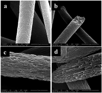
In this study, PES-based porous ultrafine fibers were chosen for the adsorption of CNTs because of the high surface area and the porous structure. For comparison, PES pure and PES/PVA porous ultrafine fibers were prepared via the electrospinning technique for further use in adsorption. Fig. 1 shows the SEM images of pure PES and PES/PVA porous ultrafine fibers. It indicates that the surface and the internal structure of both ultrafine fibers were porous. Pure PES porous ultrafine fibers displayed smaller, denser holes for the whole fiber matrix (Fig. 1a and b), which caused rapid solvent evaporation during the electrospinning process. In addition, larger and parallel porous structures were clearly observed for the surface and inner structure of PES/PVA porous ultrafine fibers. The porous structure formation mechanism might be caused by the poor solubility of PVA in DMSO. During the electrospinning, phase separation of PVA preferentially occurred with the instant increase of solution concentration caused by the rapid solvent evaporation. The PVA micro-phase region formed by the phase separation will be stretched and oriented during the rapid spinning jet extension. Therefore, after the removal of the PVA, large and parallel porous structure was formed in the whole fiber matrix.
image file: c5ra06446e-f1.tif
Fig. 1 SEM image of the surface (a) and cross section structure (b) of pure PES porous fibers and the surface (c) and cross section (d) of PES/PVA porous fibers. The magnification of those images is 50[thin space (1/6-em)]000.

Thereafter, the capacities of pure PES and PES/PVA porous fibers for CNTs adsorption were investigated. Three types of porous fibers, PES porous fibers, PES/PVA porous fibers prepared with previous additional amounts of 10 wt% and 20 wt% PVA, were prepared as the CNTs adsorbing medium in this study. As seen in Fig. 2a, very small amounts of CNTs could be observed on the surface of pure PES porous fibers. Compared with the pure PES porous fibers, there were more CNTs absorbed on the surface of the PES/PVA porous fibers prepared with a previous additional amount of 10 wt% PVA. This indicated that the larger pores would absorb better compared to the smaller porous structure. Furthermore, when increasing the amount of PVA to 20 wt%, many more CNTs were absorbed on the surface as a larger porous structure was formed. This suggests a better possibility to form a continuous conductive surface layer for the large and parallel porous structure. In this case, the PES/PVA porous fibers prepared with a previous additional amount of 20 wt% PVA were considered to be the most suitable fibers to absorb the CNTs in this study and were used as the matrix porous fibers in all the following study.


image file: c5ra06446e-f2.tif
Fig. 2 SEM image of pure PES porous fibers (a), PES/PVA (10/1, wt/wt) porous fibers (b), and PES/PVA (10/2, wt/wt) porous fibers (c) after the CNTs adsorption. Magnification of all of the images is 50[thin space (1/6-em)]000.

To immobilize the CNTs on the surface of the fibers, DMSO vapor treatment was applied. The DMSO vapor could slightly dissolve the polymer on the surface of the fibers. Because of the surface tension of the dissolved fibers' surface, the porous structure on the fibers surface would be closed and the CNTs would be anchored on the surface porous structure. The vapor treatment time would have a large influence on the formation of the conductive surface layer. The PES-based porous fibers would be destroyed if the treatment time was too long, while if the treatment time was not long enough, the CNTs would not be effectively embedded and immobilized. Fig. 3 shows the SEM images of DMSO vapor treated PES/PVA/CNTs porous ultrafine fibers for 0, 1.5, and 2 hours. The results show that with increasing time of vapor treatment, less amount of CNTs on the surface of fibers could be observed and the surface porous structure disappeared. Because there were only few CNTs on the surface of the fibers after 2 h of vapor treatment, the maximum vapor treatment time was taken as 2 h in this study. There would be two possible reasons for this phenomenon. One is that the CNTs were rinsed off from the surface of the fibers after the porous structure was closed. While the other is that the CNTs were embedded into the surface layer and formed a thin conductive layer around the fibers.


image file: c5ra06446e-f3.tif
Fig. 3 SEM images of DMSO vapor treatment of PES/PVA porous fibers after the adsorption of CNTs with time of 0 (a), 1.5 (b), and 2 h (c). The magnification of all the images is 50[thin space (1/6-em)]000.

As shown in Fig. 4, there were almost no CNTs on the internal fibers and only some could be observed on the surface; this indicates that the un-immobilized CNTs on the fibers mats were removed by the ethanol washing process. The cross-section SEM images of the PES/PVA porous fibers show that there were no CNTs in the inner porous structure, while in the surface layer some CNTs could be observed. Therefore, this result indicates that when the surface porous structure was closed, some CNTs were also enclosed into the porous structure.


image file: c5ra06446e-f4.tif
Fig. 4 SEM images of the top-view (left) and cross section (right) of PES/PVA porous fibers containing CNTs with the vapor treatment and then after rinsed by ethanol. (Please move a and b to the left side).

The TGA results could further prove this result. As seen in Fig. 5, CNTs are not degraded in the N2 atmosphere until 800 °C. For both PES/PVA porous ultrafine fibers and PES/PVA porous ultrafine fibers with the surface adsorption of CNTs, there were two regions in their weight loss trace. The first weight loss is attributed to the decomposition of PVA, while the second weight loss is that of PES, which showed that there was still some PVA left in the fiber matrix. The decomposition temperatures of the PES and PVA components were 495.8 °C and 220.5 °C, respectively. With the addition of CNTs, the thermal stability of electrospun porous PES/PVA porous ultrafine fibers increased. The start decomposition temperature of the PES/PVA porous fibers was about 150 °C, while it increased to 260 °C for the fibers after the surface adsorption of CNTs. Based on eqn (1), the content of CNTs in the PEA/PVA porous fibers was about 11 wt%. Based on the SEM characterization results, there were quite few CNTs on the surface and none in the insides of the fibers. Therefore, in this case, the only place for the presence of CNTs was the surface layer of the fibers, which makes the conductive layer on the surface of the fibers and could improve the conductivity properties of fibers with the very least amounts of CNTs.


image file: c5ra06446e-f5.tif
Fig. 5 TGA curves of PES/PVA porous fibers (a) and PES/PVA porous fibers together with CNTs (b).

To easily understand the entire procedure, a scheme is provided in Fig. 6. The CNTs were absorbed on the surface and surface porous structure. After the vapor treatment, the porous structure on the surface of fibers would disappear and thus the CNTs were embedded, forming a thin polymer/CNTs composite layer around the ultrafine fibers. During the electrospinning process, the fibers formed interweaved structures and the thin conductive composite layer could significantly improve the conductivity of the fiber mats.


image file: c5ra06446e-f6.tif
Fig. 6 The schematic of the preparation of conductive fibers for the whole procedure.

As can be seen in Table 1 and Fig. 7, with the content of the CNTs increasing, the surface resistance of fiber mats reduced significantly at the beginning, which means an obvious improvement for the conductive properties of PES/PVA porous ultrafine fibers. When the concentration of the suspension of CNTs reached 3.0 × 10⁻³ g L−1, the surface resistance decreased to 10.98 R sq−1 and with further increase in the concentration, the surface resistance did not changed. This suggests that the formation of the CNTs network in the thin composite layer was fulfilled at this concentration. The CNTs formed networks to make electric charge move freely. With further increasing the concentration, the content of CNTs in the conductive thin composite layer should be increased. However, the additional content offers no contribution to the improvement of the conductivities of the mats. As Table 2 shows, the TGA results of PES/PVA porous ultrafine fibers with different contents of CNTs are different. The TGA results showed that the real content of the CNTs in the PES/PVA porous ultrafine fiber mats was about 7 wt% when the concentration of suspension of CNTs was 3.0 × 10⁻³ g L−1. This means that only a content of 7 wt% of CNTs was required to fulfill the formation of the continuous conductive layer. Therefore, a low content of CNTs could result in a good conductivity for the fiber mats (Fig. 8).

Table 1 The different concentrations of CNTs in ethanol used for the adsorption
No. 0# 1# 2# 3# 4# 5#
C (g L−1) × 10−2 0 0.03 0.2 0.3 0.6 2.4


image file: c5ra06446e-f7.tif
Fig. 7 The electrical conductivity of PES/PVA porous ultrafine fibers with different contents of CNTs.
Table 2 The TGA results of PES/PVA porous ultrafine fibers with different CNTs concentration, (a) 0, (b) 0.03 × 10⁻² g L−1, (c) 0.2 × 10⁻² g L−1, (d) 0.3 × 10⁻² g L−1, (e) 0.6 × 10⁻² g L−1, (f) 2.4 × 10⁻² g L−1, in ethanol
Samples a b c d e f
Content (%) 0 4.08 5.56 6.99 12.69 15.00


image file: c5ra06446e-f8.tif
Fig. 8 The DSC curves of PES based with different contents of CNTs 0% (a), 4.08% (b), 5.56% (c), 6.99% (d), 12.69 (e), 15.00% (f).

The influence of surface polymer/CNTs composite layers on thermal properties of PES-based ultrafine fibers was assessed by DSC investigations. As displayed in Fig. 7, no melting peak but only the glass transition region could be observed in the DSC heating curves for all PES-based porous fibers, which indicated that the PES was an amorphous polymer. The glass transition temperatures (Tg) determined for PES-based porous ultrafine fibers with different surface CNTs contents ranged from 228–231 °C. All of them were larger than that of the pure PES ultrafine fibers (220 °C). This might be due to the restrictive movement of macromolecular chains by the incorporation of CNTs in the fibers' surface layers (Table 3).

Table 3 The DSC data determined from the DSC curves
No. 1 a b c d e f
Tg (°C) 220 229 230 231 231 231


Conclusion

In this study, PES and PES/PVA porous fibers were prepared via the electrospinning technique. The SEM characterization results showed that both the internal and surface structure were porous. Fibers were then applied to absorb the CNTs dispersed in ethanol. The results indicated that because of the large and parallel porous structure, PES/PVA fibers with PVA addition amounts of 20 wt% were more suitable to absorb CNTs. DMSO vapor was applied to close the surface porous structure and immobilize the CNTs, and vapor treatment time of 2 h was chosen as the optimal time. After vapor treatment and cleaning with ethanol, thin polymer/CNTs composite layers were self-formed on the surface of the PES-based ultrafine fibers. This was proved by further SEM characterization and TGA results. The conductive properties test showed that only 7 wt% of CNTs were required to form the continuous conductive layer and significantly increase the conductivity. There was no further enhancement of conductive property for further increase in the amount of CNTs. The results show that this method is available and could be used to prepare other types of conductive polymer fibers.

Acknowledgements

We are particularly indebted to Dr Chaoliang Zhang for assistance of SEM testing in the State Key Laboratory of Oral Diseases of Si Chuan University.

References

  1. Q. C. Zhang, L. H. Wang, Z. M. Wei, X. J. Wang, S. R. Long and J. Yang, J. Polym. Sci., Part B: Polym. Phys., 2012, 50, 1004 CrossRef CAS PubMed.
  2. P. Dayal, J. Liu, J. Kumar and T. Kyu, Macromolecules, 2007, 40, 7689 CrossRef CAS.
  3. J. W. Xie, X. R. Li and Y. N. Xia, Macromol. Rapid Commun., 2008, 29, 1775 CrossRef CAS PubMed.
  4. X. Jiang, S. H. Lim, H. Q. Mao and S. Y. Chew, Exp. Neurol., 2010, 223, 86 CrossRef PubMed.
  5. S. H. Lim and H. Q. Mao, Adv. Drug Delivery Rev., 2009, 61, 1084 CrossRef CAS PubMed.
  6. Q. Y. Lin, Z. M. Wei, M. J. Xu, S. Wang, G. H. Niu, K. P. Liu, Y. X. Duan and J. Yang, RSC Adv., 2014, 4, 14392 RSC.
  7. H. J. Lee, Z. X. Jin, A. N. Aleshin, J. Y. Lee, M. J. Goh and K. Akagi, et al., J. Am. Chem. Soc., 2004, 126, 16722 CrossRef CAS PubMed.
  8. I. S. Chronakis, S. Grapenson and A. Jakob, Polymer, 2006, 47, 1597 CrossRef CAS PubMed.
  9. S. Srinivasan, R. Ratnadurai, M. Niemann, A. Phani, D. Goswami and E. Stefanakos, Int. J. Hydrogen Energy, 2010, 35, 225 CrossRef CAS PubMed.
  10. T. S. Kang, S. W. Lee, J. Joo and J. Y. Lee, Synth. Met., 2005, 153, 61 CrossRef CAS PubMed.
  11. Q. W. Yu, H. H. Ji and Y. Y. Jian, Polym. Int., 2007, 56, 1367–1370 CrossRef PubMed.
  12. G. W. Zhen, Z. K. Xu, L. S. Wan, J. Wu, I. Christophe and S. Patrick, Macromol. Rapid Commun., 2006, 27, 516–521 CrossRef PubMed.
  13. Q. Z. Zhang, Z. C. Chang, M. F. Zhu, X. M. Mo and D. Chen, Nanotechnology, 2007, 18, 115611–115616 CrossRef.
  14. S. Wael, D. Yael and L. K. Rafail, et al., Langmuir, 2004, 20, 852–855 Search PubMed.
  15. F. Ko, I. Y. Gogots, A. Ali, N. Y. H. Naguib, G. L. Yang, C. Li and P. Willi, Adv. Mater., 2003, l5, 1161–1164 CrossRef PubMed.
  16. J. J. Ge, H. Hou, Q. Li, M. J. Graham, A. Greiner, D. H. Reneker, F. W. Harris and S. Z. D. Cheng, J. Am. Chem. Soc., 2004, 126, 15754–15761 CrossRef CAS PubMed.
  17. E. J. Ra, K. H. An, K. K. Kim, S. Y. Jeong and Y. H. Lee, Chem. Phys. Lett., 2005, 413, 188–193 CrossRef CAS PubMed.
  18. J. Liu, T. Wang, T. Uchida and S. Kumar, J. Appl. Phys., 2005, 96, 1992–1995 CAS.
  19. Y. Yu, L. Gu, C. Wang, A. Dhanabalan, P. A. van Aken and J. Maier, Angew. Chem., Int. Ed., 2009, 48, 6485–6489 CrossRef CAS PubMed.
  20. F. Ko, Y. Gogotsi, A. Ali, N. Naguib, H. Ye and G. Yang, et al., Adv. Mater., 2003, 15, 1161–1165 CrossRef CAS PubMed.
  21. L. Wang, Y. Yu, P. Chen, D. Zhang and C. Chen, J. Power Sources, 2008, 183, 717–723 CrossRef CAS PubMed.
  22. J. H. Sung, H. S. Kim, H. J. Jin, H. J. Choi and I. J. Chin, Macromolecules, 2004, 37, 9899–98902 CrossRef CAS.
  23. H. S. Kim, H. J. Jin, S. J. Myung, M. Kang and I. J. Chin, Macromol. Rapid Commun., 2006, 27, 146–151 CrossRef CAS PubMed.
  24. S. Q. Pan, L. Liu and Z. M. Huang, Acta Mater. Compositae Sin., 2008, 25, 98–104 CAS.
  25. J. F. Gao, M. J. Hu and K. Y. L. Robert, J. Mater. Chem., 2012, 22, 10867–10872 RSC.
  26. M. Havel, K. Behler, G. Korneva and Y. Gogotsi, Adv. Funct. Mater., 2008, 18, 2322–2327 CrossRef CAS PubMed.
  27. M. Kang and H. J. Jin, Colloid Polym. Sci., 2007, 285, 1163–1167 CAS.
  28. (a) S. Lukas, N. Frank and J. Wang, Fibers, 2014, 2, 109–127 Search PubMed; (b) Z. M. Wei, Q. C. Zhang and L. H. Wang, et al., Sep. Sci. Technol., 2013, 15, 2287–2292 CrossRef PubMed.

This journal is © The Royal Society of Chemistry 2015
Click here to see how this site uses Cookies. View our privacy policy here.