
Transfer of vertically aligned carbon nanotube arrays onto flexible substrates for gecko-inspired dry adhesive application†
Yang Liab,
Hao Zhangb,
Yagang Yao*c,
Taotao Lic,
Yongyi Zhangc,
Qingwen Lic and
Zhendong Dai*b
aCollege of Material Science and Technology, Nanjing University of Aeronautics and Astronautics, Nanjing 210016, China
bInstitute of Bio-inspired Structure and Surface Engineering, College of Astronautics, Nanjing University of Aeronautics and Astronautics, Nanjing 210016, China. E-mail: zddai@nuaa.edu.cn; Fax: +86-025-84892581; Tel: +86-025-84892584
cKey Laboratory of Nanodevices and Applications, Suzhou Institute of Nano-tech and Nano-bionics, Chinese Academy of Sciences, University of Chinese Academy of Sciences, Suzhou 215123, China. E-mail: ygyao2013@sinano.ac.cn; Fax: +86-512-62872552; Tel: +86-512-62872829
First published on 11th May 2015
Abstract
The gecko's extraordinary climbing ability has inspired scientists to develop synthetic dry adhesives that mimic the structure and function of gecko feet. The vertically aligned carbon nanotube (VACNT) array has been considered a potential candidate for developing gecko-inspired dry adhesive materials due to its outstanding structural and mechanical properties. However, the limited choices of growth substrates and poor interfacial bonding between VACNTs and growth substrates have restricted their application as gecko-inspired dry adhesive materials. Here, we report a versatile transfer method for transferring VACNT arrays onto flexible polymer substrates using a thermal oxidation process. This transfer method mainly focused on using the VACNT array as a gecko-inspired dry adhesive. Using the transfer method developed in our study, VACNT array-based gecko-inspired dry adhesive materials with improved adhesion property, structural stability, and self-cleaning ability can be developed. A thermal oxidation process was used to obtain free-standing VACNT arrays, resulting in the production of top-transferred and bottom-transferred structural VACNT array-based dry adhesive materials. The shear adhesive strength of the transferred VACNT array was enhanced using this method. The interfacial bonding strength of the transferred VACNT array increased nearly 15 times according to nanoscratch tests. The flexible structure of the transferred VACNT array exhibited better antifouling properties by mimicking digital hyperextension (DH) motion, which is a natural peeling motion of the gecko foot with a unique dynamic self-cleaning mechanism. These findings show that our method is an efficient method for transferring VACNT arrays and an important process for fabricating gecko-inspired VACNT array-based dry adhesive materials with high structural stability, self-cleaning ability, and high adhesive strength.
1. Introduction
Geckos have excellent climbing ability and can move freely on almost any surface, flat or inclined. The chief reason for the gecko's extraordinary climbing ability is that its toes are covered with a hierarchical structure of pliable β-keratin hairs, which comprise mesoscale lamellae, microscale setae, and nanoscale spatulae; these hairs can integrate weak van der Waals (vdW) forces into a sufficiently strong adhesive force.1–3 The gecko's locomotion and hierarchical structural adhesive systems have been extensively researched and the results have been used to fabricate gecko-mimetic climbing robots, which can perform many useful tasks such as surveillance, inspection, repair, and cleaning; they can even work in space environments.4–6 In order to mimic the gecko's exceptional climbing ability in robots, it is imperative to develop a new class of gecko-inspired dry adhesive materials that are not only sticky but also structurally stable, adaptable, and reusable.7 In recent years, synthetic polymers8,9 and vertically aligned carbon nanotube (VACNT) arrays10–12 have been developed as two major types of materials for producing gecko-inspired dry adhesive materials. Initially, polymers were used as gecko-inspired dry adhesive materials because of their structural versatility (such as polyurethane micropillars with angled mushroom tips and micro/nanoscale hierarchical polymeric hairs13,14) and simple fabrication processes (cast-molding or lithography15,16). However, they have many limitations such as poor mechanical and structural properties. In contrast, VACNT arrays are not only structurally similar to gecko foot hairs, but are also endowed with additional outstanding mechanical,17 chemical,18 electrical,19,20 and thermal properties21 and therefore are considered potential candidates for advanced gecko-inspired dry adhesive materials. An adhesive strength of more than 500 N cm−2 between a VACNT array and a glass surface has been theoretically predicted.22,23 Qu et al.10 have fabricated a hierarchically structured VACNT array with a curly entangled top layer and obtained a macroscopic adhesive strength of around 100 N cm−2, which is nearly 10 times more than that of the natural array of setae on one toe of a gecko foot and is so far the highest adhesive strength reported for VACNT array-based dry adhesive materials. Chemical vapor deposition (CVD) is commonly used to synthesize VACNT arrays. Considering the high growth temperature (around 750 °C) involved and the requirement for a buffer layer (Al2O3) on top of the growth substrate during the CVD reaction process, high-melting-point semiconductors (e.g. Si) and insulators (e.g. quartz) are considered optimal substrates for VACNT growth.24 However, poor interfacial bonding between a VACNT array and silicon substrates may cause unreliable behavior and reduced structural stability, reducing the lifespan of VACNT arrays as dry adhesives.25 In addition, compared with robust and flexible gecko toe pads, on which all the hierarchical hairs are oriented and distributed in a similar fashion,26 a silicon substrate is stiff, brittle, and fragile, thus reducing the adaptability of VACNT array-based dry adhesive materials. Therefore, it is highly desirable to develop a versatile method for transferring VACNT arrays from growth substrates onto flexible substrates to enable gecko-inspired dry adhesive applications.Recently, a few methods have been developed for transferring VACNTs onto different substrates. Abdelhalim et al.27 reported the fabrication of high-quality stable carbon nanotube (CNT) films on flexible substrates via a spray deposition method, but the CNTs that were obtained exhibited randomly oriented morphology. Mäklin et al.28 adopted a solder transfer method for micro-finned CNT structures. Thin films of Cr/Au were deposited on CNT tips to enhance the successful transfer of CNT films to the Ag solder pads of ceramic chips, which is a complex and expensive process. Kang et al.29 used a polydimethylsiloxane polymer as an intermediate to transfer a VACNT array, but this process has low efficiency and needs to be improved. Moreover, previous studies, especially those on polymer-based transfer techniques of VACNT arrays, mainly focused on electrical or field emission performance;24,30 the mechanical performance was seldom investigated for transferred VACNT arrays.
Geckos possess outstanding adhesive ability and also antifouling properties, which help them walk persistently in various environments. Hu et al.32 studied the self-cleaning ability of geckos during locomotion and proposed an intrinsic dynamic self-cleaning mechanism associated with both the structure of gecko toe pads and their natural peeling motion called digital hyperextension (DH). During hyperextended peeling, the setae on a gecko foot roll up, detach from the substrate and then generate high inertial forces to separate dirt particles from the spatulae. The rate of recovery of adhesion ability in geckos with DH motion is double that of those without DH. Self-cleaning performance of a gecko-inspired dry adhesive is a basic requirement for achieving the reusable and reliable application of gecko-mimetic robots. VACNT arrays, as a potential dry-adhesive candidate, exhibit structural similarity with gecko foot hairs.10 However, VACNT arrays grown on a rigid silicon substrate are not suitable for achieving the peeling and scrolling of the DH motion and therefore could not enable the dynamic self-cleaning mechanism.
In this work, a fast, low-cost, versatile, and easy-to-scale-up transfer method of VACNT arrays was developed for fabricating a gecko-inspired dry adhesive. An as-grown VACNT array was transferred onto a flexible polyethylene terephthalate (PET) substrate via a thermoplastic polyurethane (TPU) intermediate after carrying out a brief thermal oxidation pretreatment of VACNT arrays. Morphological and structural characterizations of VACNT arrays were carried out both before and after the transfer.
2. Experimental section
2.1 VACNT array synthesis
The process of growth of a VACNT array mainly includes the deposition of catalysts and precipitation of CNT. A Si/SiO2 wafer was chosen as the growth substrate. A 20 nm-thick Al2O3 layer and a 2 nm-thick Fe film were deposited on the Si/SiO2 substrate as catalysts using an electron beam system (E-beam 500, Xingnan, Chengdu, China). Thermal CVD was used for growing VACNT arrays in a tubular furnace (OTF-1200X-80, Kejing, Hefei, China). For the entire reaction process, 1500 standard cubic centimeters per minute (sccm) Ar was used as the carrier gas. At nearly 650 °C, 500 sccm H2 was injected into the furnace for pretreatment of the catalyst and a VACNT array was precipitated when 250 sccm C2H2 was introduced into the reactor at 720 °C. The reaction time was 3–30 min and the length of the VACNT array varied between 100 and 800 μm. When the growth ended, the C2H2 and H2 supplies were stopped but Ar was kept flowing until the temperature decreased to room temperature.2.2 Transfer process of VACNT array
TPU (Desmopan 786L, Bayer, Germany) was chosen as the transfer medium because of its high mechanical strength and good flexibility. The transfer process is illustrated schematically in Fig. 1a. TPU particles were dissolved in N,N-dimethylformamide (DMF) solution (mass ratio 1![[thin space (1/6-em)]](https://www.rsc.org/images/entities/char_2009.gif) :4) at 70 °C. Then, a drop of the TPU solution (100 μL) was spin-coated (KW-4A, IMECAS, China) on top of a flexible PET plastic sheet for use as the transfer substrate. The spin speed was set at 5000 rpm for 30 s. Meanwhile, the as-grown VACNT array was placed in the tubular furnace for a 5 min thermal oxidation pretreatment step (500 °C) in air, which assists in the detachment of nanotube films from Si substrates. After the detachment, the pretreated VACNT array was transferred with either its top side (top transfer) or bottom side (bottom transfer) bonded to a PET plastic sheet under a normal pressure of ∼0.5 N cm−2. Then, this integrated structure was put into an oven at 70 °C for 15–30 min to polymerize TPU; finally, the flexible PET plastic sheet with the transferred VACNT array was peeled off.
:4) at 70 °C. Then, a drop of the TPU solution (100 μL) was spin-coated (KW-4A, IMECAS, China) on top of a flexible PET plastic sheet for use as the transfer substrate. The spin speed was set at 5000 rpm for 30 s. Meanwhile, the as-grown VACNT array was placed in the tubular furnace for a 5 min thermal oxidation pretreatment step (500 °C) in air, which assists in the detachment of nanotube films from Si substrates. After the detachment, the pretreated VACNT array was transferred with either its top side (top transfer) or bottom side (bottom transfer) bonded to a PET plastic sheet under a normal pressure of ∼0.5 N cm−2. Then, this integrated structure was put into an oven at 70 °C for 15–30 min to polymerize TPU; finally, the flexible PET plastic sheet with the transferred VACNT array was peeled off.
 | ||
| Fig. 1 (a) Schematic of the transfer process of a vertically aligned carbon nanotube (VACNT) array onto a PET substrate: (1) thermal oxidation process of as-grown VACNT array (AC) at 500 °C for 10 min. (2) TPU layer was spin-coated on a PET substrate. (3) Assembly of top-transferred VACNT array (TC) and bottom-transferred VACNT array (BC) samples and curing in an oven at 70 °C for 15–30 min. (4) Transferred VACNT arrays; (b) optical image of AC on silicon substrate; (c) detached free-standing VACNT array after thermal oxidation process; bending and scrolling of (d) TC sample and (e) BC sample. | ||
2.3 Characterization
High-resolution field emission scanning electron microscopy (HR-FESEM, Hitachi S-4800, Japan) was used to characterize the morphology of as-grown VACNT arrays at an operating voltage of 10 kV. Micro-Raman spectroscopy (Raman, Labram HR 800, Japan) was used to characterize the quality (graphitic ordering, defects, etc.) of VACNT arrays. The height of a VACNT array was measured via optical microscopy (SK-2000H).2.4 Mechanical measurement
To determine the adhesive properties of VACNT arrays, two different evaluation systems were used. One was the hanging-weight system, which is simple and intuitive. In this system, different weights can be directly suspended to test the shear adhesive strength of VACNT arrays. VACNT array samples were attached to a plastic sheet by 3M Scotch tape and then finger-pressed onto a glass surface under a preload of nearly 40 N cm−2. Different weights were hung on the end of the plastic sheet. The weights were increased until detachment occurred.The other system is the multifunctional material adhesion and friction test platform (IBSS-2, NBIT, Nanjing, China), which was used to accurately analyze the adhesive behavior of VACNT array-based dry adhesive materials. The platform contains a 2-dimensional force sensor with a force resolution of approximately 1 mN. An automated stage driven by a motor can be moved in both vertical and horizontal directions to test the shear adhesive strength of VACNT array-based dry adhesive materials. A glass slide was used as an adhesive test surface and was mounted on a circular stage. A VACNT array was attached to the sample stage and moved along with the force sensor. Initially, when the top surface of the VACNT array was normally in contact with the glass slide, a microshear dragging process was implemented to help align non-aligned and entangled CNTs along the shear direction, which could further increase the side-wall contact area.10 Then, the VACNT array along with the sample stage was moved vertically at a constant speed of 5 μm s−1 and was then compressed against the glass slide until a preload of ∼18 N cm−2 was achieved, after which the samples were released to achieve the normal preload of 0 N on the CNT sample. Without normally being detached from the glass surface, the CNT samples were moved along the shear direction under no external compression until stick-slip motion was observed during a dynamic friction process.40 The responses to force, along with the time, were continuously recorded, which intuitively reflected the adhesive behavior of VACNT array-based dry adhesive materials so that they can be used in practical applications such as the fabrication of a gecko-inspired climbing robot.31
The bonding strength between VACNTs and substrates was measured via a nanoscratch-based technique proposed by Lahiri et al.25 The Nano Indenter G200 (Agilent, America) was used to quantify the bonding strength between VACNTs and two different substrates, Si and PET, one having Al2O3 and Fe as buffer and catalyst layers, respectively, and the other having TPU as a transfer medium layer on top. VACNT array samples of height 100 μm were tested. A bare silicon substrate with Al2O3/Fe layers and a PET substrate with a TPU layer were used as control groups. During scratching, a standard conical diamond tip (with 5 μm tip radius and 90° angle) was used with a normal preload of 150 μN. The length of each scratch was kept constant at 100 μm. The tip started to scratch from a bare surface and then encountered the VACNT array. While moving through the VACNT array, the indenter tip experienced an extra opposing force and uprooted the CNTs. Yu et al. have described the scratch process in detail.23
The antifouling property of the VACNT array was achieved by mimicking the DH peeling and scrolling motion of a gecko walking in a dirty environment.32 Setae hairs of the gecko foot could be scrolled up and spread out progressively from the substrate during DH motion and, if they restricted their DH motion, geckos could lift their limbs to detach their toes from the substrate, which was considered limb motion (LM) by Hu et al.32 Silica particles with diameters ranging from 5 to 10 μm were used as a fouling agent in this study. VACNT array samples (10 mm × 20 mm) were first covered with silicon particles (5–10 μm diameter) and then finger-pressed with a preload near 40 N cm−2. A pair of tweezers was used to scroll and peel the transferred VACNT array samples to mimic DH motion. Due to the limitation of the rigid silicon substrate, as-grown samples were directly detached from the substrate with tweezers in crack-growth mode, just like the LM motion of a gecko.32 Both motions were repeated 10 times. The fouling state of VACNT arrays was examined and recorded by SEM.
3. Results and discussion
3.1 Transfer process of VACNT array
The structural integrity and stability of VACNT arrays are very important for their application as dry adhesive materials. However, when the transfer process is carried out without any oxidation pretreatment, CNTs usually do not detach completely and always leave some residues on the silicon substrate (Fig. S1 in the ESI†). Therefore, in our experiment, an additional oxidation pretreatment was introduced to help the complete transfer of the VACNT array. Fig. 1a schematically illustrates the transfer process of a VACNT array. First, the synthesized VACNT array (Fig. 1b) was directly placed in a thermal oxidation environment in air at 500 °C for 10 min and then cooled to room temperature. Then, a free-standing VACNT array was removed with tweezers (Fig. 1c). The base-growth mechanism, in which the CNT continues to grow from particles anchored to the substrate,33 illustrates that the roots of the CVD-synthesized VACNT array become wrapped by catalyst particles with strong adherence to the surface of the substrate. When the temperature was ∼500 °C, oxygen atoms would etch carbon atoms near the root ends,34–36 making the as-grown VACNT array (AC) much easier to detach from the silicon substrate. Secondly, a drop of TPU solution was spin-coated (5000 rpm for 30 s) on a flexible plastic PET substrate. Thirdly, both the top and bottom sides of the free-standing VACNT array can be used as a new bonding interface. The top-transferred VACNT array (TC) and bottom-transferred VACNT array (BC) were integrated together under a normal pressure of about 0.5 N cm−2. Finally, TC and BC samples were obtained after the polymerization of TPU. The VACNT array transferred onto the flexible PET plastic sheet can be folded many times without any obvious structural damage, as shown in Fig. 1d and e. The flexible and foldable dry adhesive can help increase the real contact area on coming into contact with uneven surfaces, as in the natural environment of geckos. Therefore, the transferred VACNT array can be beneficial in improving the flexibility and adaptability of VACNT array-based dry adhesive materials.In addition, the transfer method developed here can be widely used to transfer VACNT arrays of different sizes onto various substrates such as copper foils, glass, and even paper, as shown in Fig. S2 in the ESI.† The concentration of the transfer medium has obvious effects on the results of the transfer and thus needs to be optimized to achieve the structural integrity of the transferred VACNT array, as shown in Fig. S3 in the ESI.† The mass concentration of the TPU solution was set at 10%, 15%, 20%, and 25%. From the optical images shown in Fig. S3,† it is clear that if the concentration of the TPU solution is low (10% and 15%), all CNTs cannot attach to the polymer layer and therefore easily drop from the interface. At higher concentrations (25%), the entire VACNT array would be embedded in the polymer layer while some parts of the polymer would shrink, thus destroying the morphology of the top surface and the vertically aligned structure of the transferred array. Typically, the most appropriate concentration used was approximately 20 mass% TPU; with this concentration, the VACNT array can be firmly transferred onto the polymer interface and the vertically aligned structure is also retained. Therefore, 20 mass% TPU can be used to manufacture gecko-inspired dry adhesive materials.
SEM images of AC, TC, and BC samples showing typical top surfaces and interfacial bonding morphology are presented in Fig. 2. Fig. 2a–c illustrate the interfacial connection between VACNTs and silicon substrates. It can be seen that CNTs only touch the flat surface of the silicon substrate and the edge of the VACNT array even becomes detached from the substrate. Some nanoparticles (red circle in Fig. 2c) can be found near the bottom of the VACNT array, which provides evidence that the base-growth mechanism of VACNT arrays is available.33 CNTs on the top surface (Fig. 2d) are randomly distributed; they are curly and entangled and form clusters with small clumps. Fig. 2e–g show the interfacial bonding of TC with the polymer substrate, where the original top surface of the VACNT array was immersed in a polymer solution. SEM images illustrate that the transferred VACNT array retained its vertically aligned structure and a large number of CNTs were embedded in the polymer layer (Fig. 2g). Fig. 2h shows the morphology of the top, which is the original bottom surface. Compared with Fig. 2d, CNTs of the new top surface (i.e., the original bottom surface) were more uniformly distributed without obvious curly, entangled morphologies. Although CNTs were no longer clustered into clumps, they could retain their vertically aligned structure and formed separate bundles (red circle in Fig. 2h). Fig. 2i–k show interfacial bonding morphologies of BC with the polymer substrate. The detached free-standing VACNT array was directly embedded in the polymer layer, keeping the vertically aligned body structure and original top surface unchanged. Moreover, the polymer infiltrated the bottom side of CNTs and formed a good interfacial bond, as deduced from Fig. 2j and k. Fig. 2l shows the top surface, which is similar to that shown in Fig. 2d, because the bottom transfer method can keep the top surface of a VACNT array unchanged.
 | ||
| Fig. 2 SEM images of interfacial bonding of AC (a–c), TC (e–g), and BC (i–k); SEM images of top surfaces of AC (d), TC (h), and BC (l). | ||
Raman characterization was carried out to determine the quality of VACNT arrays. For CNTs, the D band (at ∼1350 cm−1) represents disordered or amorphous carbon and the G band (at ∼1580 cm−1) indicates ordered graphite.37 As shown in Fig. 3, the G/D peak intensity ratios of both BC and AC are near 0.85, which indicates that oxidation will not change the quality of VACNT arrays. However, the G/D peak intensity ratio of TC is higher (1.32) than those of the other two surfaces. This implies that the bottom side of AC exhibits better properties such as good graphitization and alignment. These results are consistent with those obtained by SEM analysis. Via the proposed transfer method, transferred VACNT arrays with different top morphologies can be obtained, thus providing a further option for using VACNT arrays for different applications.
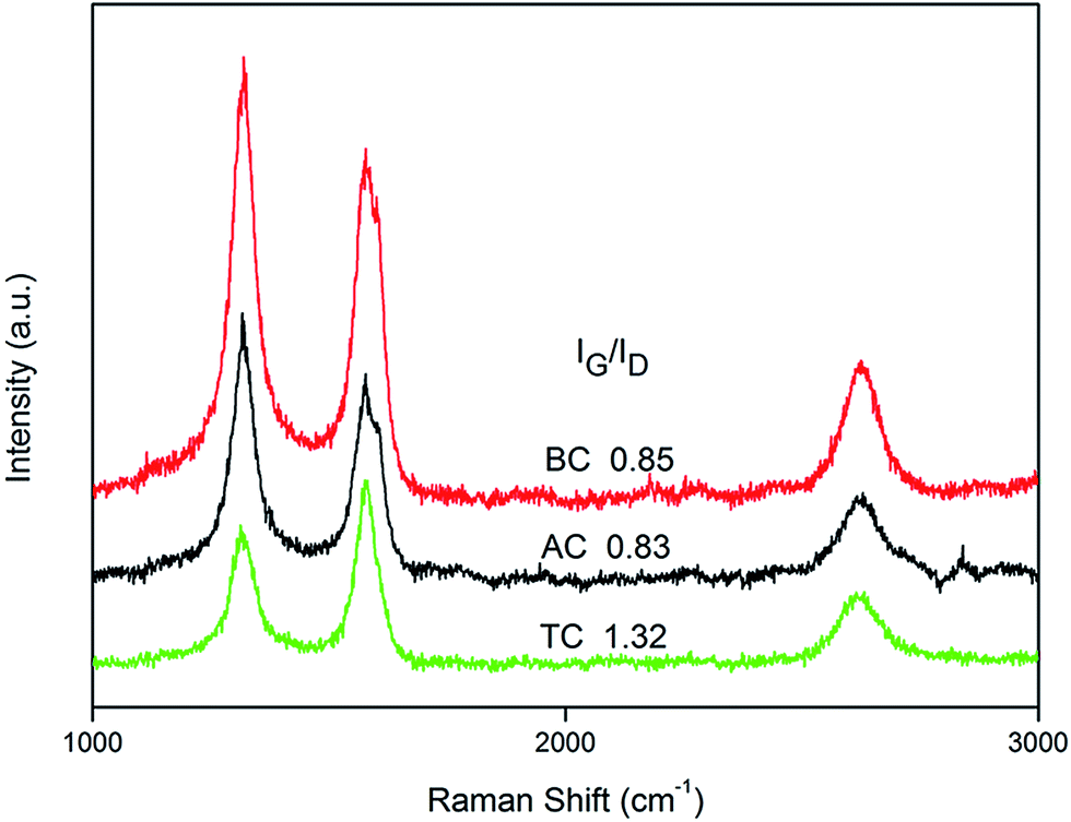 | ||
| Fig. 3 Micro-Raman spectra of AC, TC, and BC samples. | ||
3.2 Test of interfacial adhesive strength of transferred VACNT array
AC, TC, and BC samples (5 mm × 5 mm, length ∼400 μm; red circle in Fig. 4a) were finger-pressed onto a glass surface as shown in Fig. 4a. Fig. 4b shows the hanging strength calculated based on the hanging weights of AC, TC, and BC (10 samples per group) and Fig. 4c1 schematically illustrates the test system. The results show that AC can only support weights of nearly 50 g and its hanging strength is around 2 N cm−2. When the weight was further increased, the VACNT array suddenly detached from the silicon substrate, leaving the main VACNT array still adhering to the glass surface (schematically illustrated in Fig. 4c2). This is because the interfacial bonding between the VACNT array and the silicon substrate in AC is so weak that only a small amount of weight can be suspended. As soon as the hanging weights became greater than the interfacial bonding strength (around 2 N cm−2), the VACNT array was detached from the silicon substrate. However, contact between the CNTs and the glass surface was still maintained (after detachment) and the silicon substrate still adhered to the PET sheet.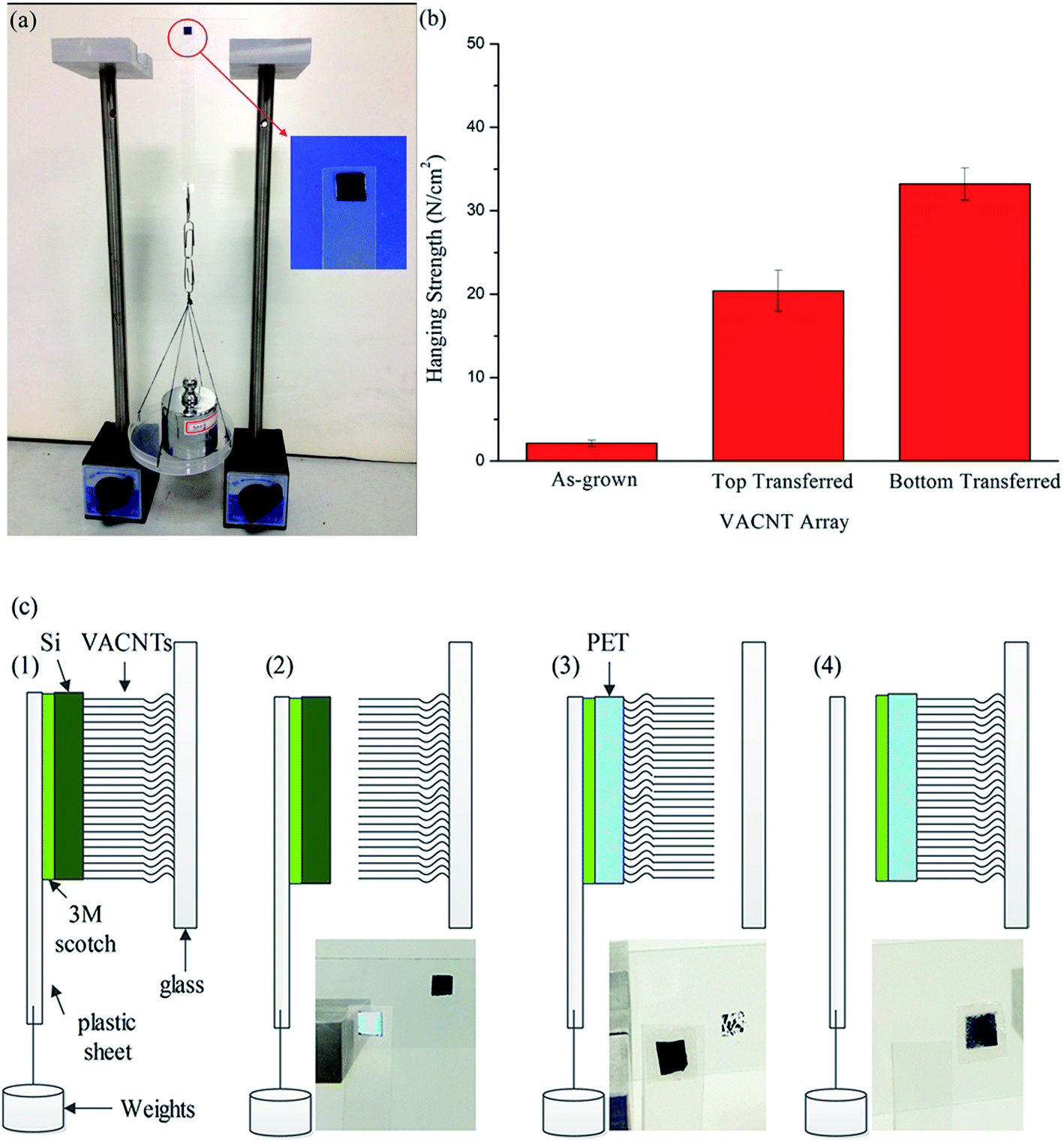 | ||
| Fig. 4 Adhesion tests of VACNT array with a hanging-weights system. (a) Image of the hanging-weights system; (b) to find the shear adhesive strength of AC, TC, and BC samples, 10 samples were tested for AC, TC, and BC, respectively. The preload strength was nearly 40 N cm−2 by finger-pressing; (c) schematics of different test states of AC, TC, and BC: (1) adhesion state of AC (hanging weight 50 g). (2) Detachment of AC (hanging weight over 50 g and separation between silicon substrate and CNTs). (3) Detachment of TC (hanging weight over 550 g and separation between CNTs and glass slide). (4) Detachment of BC (hanging weight over 850 g and separation between plastic sheet and 3M adhesive). | ||
For the adhesion test with TC samples, the maximum hanging weight was increased to around 550 g (20 N cm−2). On further increasing the weight, the TC sample became detached from the glass substrate, leaving some CNT residues attached to the glass surface. In this step, detachment occurred between the VACNTs and the glass surface (schematically illustrated in Fig. 4c3). Compared with AC, the interfacial bonding strength between VACNTs and the PET sheet was increased dramatically (>20 N cm−2). During the test, the shear adhesive strength of TC with the glass surface was near 20 N cm−2, which was lower than the interfacial bonding strength of TC and the adhesive strength of 3M Scotch tape.
For testing BC samples, a sustained weight of 850 g (32 N cm−2) can be achieved, which is higher than that for TC (20 N cm−2). To our surprise, on increasing the weight, detachment occurred between the 3M Scotch tape and the plastic sheet. The BC sample still firmly adhered to the glass surface (schematically illustrated in Fig. 4c4). This interesting result implies that both the adhesive strength between VACNTs and the glass surface and the interfacial bonding strength of BC were higher than the hanging strength (32 N cm−2), thus breaking the interface between the 3M adhesive and the plastic sheet. At the same time, BC samples exhibited stronger adhesion than TC samples and a markedly increased interfacial bonding strength compared with that of AC.
The SEM images in Fig. 2 show that CNTs on the top surface of BC samples (Fig. 2l) are arranged in a more disorderly manner than on TC samples (Fig. 2h). The curly, entangled, randomly distributed CNTs can help increase the contact area of BC samples during preloading by finger-pressing, while the uniformly distributed CNTs made more point-by-point contact with the glass surface, thus decreasing the contact area of TC samples. It is known that the contact area of fibers with a substrate is related to the adhesive strength;38,39 therefore, the higher the contact area of the BC samples is, the higher the adhesive strength is. In addition, due to an increase in interfacial bonding after the transfer process, the structural stability and adhesive strength of BC and TC samples also increased and they therefore have the potential to be used as gecko-inspired dry adhesive materials.
3.3 Shear adhesive behavior of transferred VACNT array
TC and BC samples (length ∼400 μm) were prepared to a size of 5 mm × 5 mm and mounted on the sample stage of a multifunctional material adhesion and friction test platform (Fig. 5a) to precisely investigate their shear adhesive behavior. The whole test process is schematically illustrated in Fig. 5b as described in the experimental part. | ||
| Fig. 5 (a) Adhesion test of VACNT array with a multifunctional material adhesion and friction test platform (IBSS-2, NBIT, Nanjing, China); (b) schematics of preloading, retraction, and shear frictional test; variations in adhesive strength as a function of movement time of TC sample (c) and BC sample (d). | ||
The relationships between the adhesive strength and movement time, which are shown in Fig. 5c and d, were obtained by measuring the shear adhesive force under preloading, retraction, and shear friction processes for TC and BC samples. Both samples exhibited a similar adhesive behavior: a microdrag process was conducted at the contact point and then loading and unloading of the preload (18 N cm−2) was completed. When the preload was completely retracted and continued to move along the interfacial direction, the shear adhesive strength increased monotonically with time, which indicates a static frictional adhesion process. After the maximum value of the shear adhesive strength was reached, a plateau with a slightly decreased value was produced for a few seconds, which is considered as the stick-slip phenomenon, during the dynamic frictional adhesion process of CNT hairs.40 The shear adhesive strength then quickly decreased, which indicates that the dry adhesive slipped and jumped off. The values of the maximum shear adhesive strength were approximately 14.9 and 22.7 N cm−2 for TC and BC samples, respectively. The values of the adhesion coefficient λ (the ratio of the adhesive strength to the preload strength) were 0.83 and 1.26 for TC and BC samples, respectively. The shear adhesive strength of the BC sample is higher than that of the TC sample and even that that of a natural gecko foot (∼10 N cm−2).41 It is obvious that BC shows much more potential for gecko-inspired dry adhesive applications. Therefore, for the interfacial bonding test using a nanoscratching method and self-cleaning ability test in the following discussion, BC and AC samples were chosen to be contrasted and analyzed. Compared with the hanging strength (20 and 32 N cm−2 for TC and BC samples, respectively), the shear adhesive strength obtained using the test platform was somewhat less. This occurred probably because of the use of a different preloading process between the two test methods. It has been widely proved that adhesive strength increases with increasing preload.42,43 For preloading by finger-pressing in a hanging-weights system, the preload (40 N cm−2) is far larger than the 18 N cm−2 provided by the sample stage (which is limited by the maximum measurement range of the force sensor, which is 5 N), thus enhancing the results for adhesive strength of the hanging-weights system. The effect of preloading on the adhesive strength of BC and TC samples was also investigated with the test platform, as shown in Fig. S4 in the ESI,† and the adhesive strengths increased with the applied preload strength. It is well known that van der Waals forces are mainly responsible for the adhesive property of CNTs10 and increasing the contact area between CNTs and the surface will help to increase the adhesive strength.38,39 Therefore, increasing the preload strength will create a larger contact area between CNTs and the glass surface and further increase the adhesive strength of the VACNT array. Furthermore, compared with the rigid, flat surface of the sample stage, the surface of a finger is soft and adaptable, which could further increase the real contact area between CNTs and the test surface and thereby increase the adhesive strength. The adhesive behavior under a certain preload is quite important for precisely controlling the adhesion of CNT array-based dry adhesive materials used for fabricating gecko-mimetic climbing robots.
3.4 Nanoscratch tests for interfacial bonding
The nanoscratch method was used to quantitatively characterize the interfacial bonding strength between VACNT arrays and different substrates. As shown in Fig. 6a, a 150 μN preload was applied during the nanoscratch between 20 and 120 μm scratch distances. For AC and BC samples, the nanoscratch process started from the bare substrate, resulting in scratched VACNT arrays. Fig. 6c shows the lateral force on the tip versus the scratch distance for AC and a bare silicon substrate. When the indenter tip came into contact with CNTs on the silicon substrate, the lateral force suddenly increased to ∼120 μN and then maintained a constant response during the entire scratch process. On the bare silicon substrate, the lateral force on the tip was kept around 50 μN. A SEM image of the scratched AC is presented in Fig. 6e, which shows that CNTs were completely uprooted and removed from the silicon substrate and formed a triangular space with CNTs rolled upward. Fig. 6d (for BC and a bare PET substrate) shows that when moving through the bare PET substrate, the lateral force increased to 400 μN compared with scratching the bare Si substrate (50 μN) because of the presence of a TPU layer which was spin-coated on the top surface of the PET substrate. The surface of the TPU layer is rougher than the silicon substrate with Al2O3/Fe layers; as a result, it increased the friction at the indenter tip. For the BC sample, the lateral force increased linearly with the scratch distance when in contact with the VACNT array and the maximum lateral force was nearly 2250 μN. From the SEM image shown in Fig. 6f, it is clear that VACNTs transferred by the TPU layer on the PET substrate detached incompletely and accumulated at the front edge of the indenter tip, leading to a linear increase in the lateral force. From the plots of lateral force and SEM images, it is obvious that CNTs transferred onto the PET substrate exhibited stronger interfacial bonding; as a result, CNTs could not be easily detached from the substrate by the indenter tip. This result is further illustrated in Fig. 6b, which shows increments in the lateral force for AC and BC samples plotted for 10 scratches per sample; a schematic of the nanoscratch process is shown in the inset. The increased lateral force can represent the interfacial bonding between VACNTs and different substrates.25 The increment for BC is much higher (15 times) than that for AC, which implies that the transfer method that is proposed here increased the bonding strength and structural stability of the VACNT array applied as a gecko-inspired dry adhesive material. | ||
| Fig. 6 Nanoscratch of VACNT array for interfacial bonding test. (a) Normal preload (150 μN) on the Nano Indenter during scratching; (b) increment in lateral force for AC and BC; the inset schematically illustrates the nanoscratch process; (c) lateral force on AC and bare Si substrate versus scratch distance; (d) lateral force on BC and bare PET substrate versus scratch distance; SEM images of AC (e) and BC (f) after nanoscratch tests. | ||
3.5 Self-cleaning property of transferred VACNT array-based dry adhesive materials
Fig. 1b and d show that AC samples cannot be folded or curled, whereas BC samples could be, in a manner similar to the movement of the gecko foot pad shown by Hu et al.32 Therefore, it can be assumed that the transfer method presented in our study could be beneficial for fabricating VACNT arrays that could mimic the DH motion of geckos to enhance their dynamic self-cleaning performance as outstanding CNT array-based dry adhesive materials. Fig. 7a and b show the mimetic DH and LM motions using tweezers, as described in the experimental section. SEM images of contaminated top surfaces of AC and BC samples are shown in Fig. 7c and d, respectively, where silicon particles adhere densely to their top surfaces. Fig. 7e and f show SEM images of the top surfaces of AC and BC samples after repeating the mimetic DH and LM motion. The BC sample displays a cleaner, clearer surface with only a few small silicon particle residues compared with those in the AC sample. Although the self-cleaning ability cannot be quantitatively evaluated only by contrasting SEM images, it is still evident that the top surface of the BC sample exhibited greater antifouling properties, with fewer and smaller silicon particles left on top. This result proves that a VACNT array transferred onto a flexible substrate can mimic the DH motion of geckos to exhibit better antifouling properties, which shows that the VACNT array has better potential for developing a self-cleaning ability similar to that possessed by geckos. | ||
| Fig. 7 Mimicking the DH motion of a gecko foot by shaking AC (a) and scrolling BC (b); SEM images of AC (c) and BC (d) contaminated by silicon particles; SEM images of the self-cleaned state of AC (e) and BC (f) via mimicking the digital hyperextension of a live gecko. | ||
It has been proved that with DH motion a dynamic self-cleaning mechanism could help a gecko overcome a substantially larger adhesion force between setae and particles than that without DH motion.32 During hyperextended motion, arrays of setae with spatulae on top were rolled up and spread out progressively from the substrate. This scrolling motion accumulated elastic energy in each seta in contact within the peeling zone and finally led to a dynamic jump-off and the generation of an inertial force large enough to dislodge dirt particles. The dynamic effect could also be used to interpret scrolled and peeled transferred VACNT array samples with better antifouling properties. The AC sample could not be scrolled and was directly detached from the glass substrate; therefore no accumulation of elastic energy or jump-off process took place.
However, the mechanism of the self-cleaning ability possessed by geckos is still not completely understood. Increasing attention has been paid to investigating this mechanism fundamentally and some other self-cleaning mechanisms have also been investigated, such as the lotus effect44,45 and contact self-cleaning with energy disequilibrium,46–48 and even the chemical secretion of a gecko's footprints has been considered.49 Therefore, DH motion could not be the only feature responsible for the self-cleaning ability and other factors that could affect the self-cleaning ability of a VACNT array need to be considered in future work.
4. Conclusion
In summary, we have presented a transfer method to fabricate VACNT array-based dry adhesive materials on a flexible PET substrate with TPU as intermediate. A thermal oxidation process was introduced to obtain free-standing VACNT arrays, which resulted in the production of top-transferred and bottom-transferred structural VACNT array-based dry adhesive materials. The interfacial bonding strength of the transferred VACNT array was enhanced significantly and improved adhesive behavior was exhibited. The flexible structure of the transferred VACNT array showed better antifouling properties by mimicking the DH motion of a gecko foot. We obtained a stable structure of VACNT array-based dry adhesive materials with strong interfacial bonding, high adhesive strength, and the ability to retain antifouling properties, which are favorable conditions for using VACNT arrays as gecko-inspired dry adhesives. This work reveals a new direction for the biomimetic design of VACNT array-based gecko-inspired dry adhesive materials with high reusability and reliable properties. Although more efforts are required to achieve better understanding of this issue, we still believe that transferring a VACNT array onto flexible substrates is the first step for the application of CNT array-based dry adhesive materials.Acknowledgements
This work was supported by the National Natural Science Foundation of China (no. 51275237, no. 51372265, and no. 51435008 (key project)), the Natural Science Foundation of Jiangsu Province, China (no. BK20140392), and the Project Funded by the Priority Academic Program Development of Jiangsu Higher Education Institutions.References
- A. P. Russell, Integr. Comp. Biol., 2002, 42, 1154–1163 CrossRef PubMed.
- K. Autumn and N. Gravish, Philos. Trans. R. Soc., A, 2008, 366, 1575–1590 CrossRef CAS PubMed.
- K. Autumn, M. Sitti, Y. A. Liang, A. M. Peattie, W. R. Hansen, S. Sponberg, T. W. Kenny, R. Fearing, J. N. Israelachvili and J. R. Full, Proc. Natl. Acad. Sci. U. S. A., 2002, 99, 12252–12256 CrossRef CAS PubMed.
- Z. D. Dai and J. R. Sun, J. Bionic. Eng., 2007, 4, 91–95 CrossRef.
- L. Q. Dai, H. Zhang and Z. D. Dai, Robot, 2008, 30, 182–186 Search PubMed.
- M. Carlo and S. Metin, J. Bionic. Eng., 2006, 3, 115–125 CrossRef.
- M. Sitti and R. S. Fearing, J. Adhes. Sci. Technol., 2003, 17, 1055–1073 CrossRef CAS PubMed.
- Y. Mengüç, S. Y. Yang, S. Kim, J. A. Rogers and M. Sitti, Adv. Funct. Mater., 2012, 22, 1246–1254 CrossRef PubMed.
- H. Lee and B. Bhushan, J. Colloid Interface Sci., 2012, 372, 231–238 CrossRef CAS PubMed.
- L. T. Qu, L. M. Dai, M. Stone, Z. H. Xia and Z. L. Wang, Science, 2008, 322, 238–242 CrossRef CAS PubMed.
- L. H. Ge, S. Sethi, L. J. Ci, P. M. Ajayan and A. Dhinojwala, Proc. Natl. Acad. Sci. U. S. A., 2007, 104, 10792–10795 CrossRef CAS PubMed.
- Y. Li, H. Zhang, G. Xu, L. Gong, Z. Z. Yong, Q. W. Li and Z. D. Dai, SPIE Smart Structures and Materials + Nondestructive Evaluation and Health Monitoring, San Diego, 2013 Search PubMed.
- M. P. Murphy, B. Aksak and M. Sitti, Small, 2009, 5, 170–175 CrossRef CAS PubMed.
- H. E. Jeong, J. K. Lee, H. N. Kim, S. H. Moon and K. Y. Suh, Proc. Natl. Acad. Sci. U. S. A., 2009, 106, 5639–5644 CrossRef CAS PubMed.
- M. Sitti and R. S. Fearing, J. Adhes. Sci. Technol., 2003, 17, 1055–1073 CrossRef CAS PubMed.
- B. Aksak, M. P. Murphy and M. Sitti, Langmuir, 2007, 23, 3322–3332 CrossRef CAS PubMed.
- M. S. Dresselhaus, G. Dresselhaus and P. C. Eklund, Science of fullerenes and carbon nanotubes: their properties and applications, Academic Press, San Diego CA, 1996, pp. 765–802 Search PubMed.
- J. M. Bonard, J. P. Salvetat, T. Stockli, W. A. de Heer, L. Forró and A. Châtelain, Appl. Phys. Lett., 1998, 73, 918–920 CrossRef CAS PubMed.
- T. Dürkop, S. A. Getty, E. Cobas and M. S. Fuhrer, Nano Lett., 2004, 4, 35–39 CrossRef.
- Z. Yao, C. L. Kane and C. Dekker, Phys. Rev. Lett., 2000, 84, 2941–2944 CrossRef CAS.
- J. Hone, M. Whitney and A. Zettl, Phys. Rev. B: Condens. Matter Mater. Phys., 1999, 59, 2514–2516 CrossRef.
- Y. Zhao, T. Tong, L. Delzeit, A. Kashani, M. Meyyappan and A. Majumdar, J. Vac. Sci. Technol., B: Microelectron. Nanometer Struct.–Process., Meas., Phenom., 2006, 24, 331–335 CrossRef CAS.
- M. F. Yu, T. Kowalewski and R. S. Ruoff, Phys. Rev. Lett., 2001, 86, 87–90 CrossRef CAS.
- Y. Zhu, X. D. Lim, M. C. Sim, C. T. Lim and C. H. Sow, Nanotechnology, 2008, 19, 325304 CrossRef PubMed.
- I. Lahiri, D. Lahiri, S. Jin, A. Agarwal and W. Choi, ACS Nano, 2011, 5, 780–787 CrossRef CAS PubMed.
- K. Autumn, C. Majidi, R. E. Groff, A. Dittmore and R. Fearing, J. Exp. Biol., 2006, 209, 3558–3568 CrossRef CAS PubMed.
- A. Abdelhalim, A. Abdellah, G. Scarpa and P. Lugli, Carbon, 2013, 61, 72–79 CrossRef CAS PubMed.
- J. Mäklin, N. Halonen, O. Pitkänen, G. Tóth and K. Kordás, Appl. Therm. Eng., 2014, 65, 539–543 CrossRef PubMed.
- S. J. Kang, C. Kocabas, H. S. Kim, Q. Cao, M. A. Meitl, D. Y. Khang and J. A. Rogers, Nano Lett., 2007, 7, 3343–3348 CrossRef CAS PubMed.
- P. Mishra, N. H. Tai, Harsh and S. S. Islam, Mater. Res. Bull., 2013, 48, 2804–2808 CrossRef CAS PubMed.
- B. Aksak, M. P. Murphy and M. Sitti, Robotics and Automation, 2008. ICRA 2008. IEEE International Conference on. IEEE, 2008, pp. 3058–3063 Search PubMed.
- S. Hu, S. Lopez, P. H. Niewiarowski and Z. Xia, J. R. Soc., Interface, 2012, 9, 2781–2790 CrossRef PubMed.
- R. T. K. Baker, Carbon, 1989, 27, 315–323 CrossRef CAS.
- P. X. Hou, C. Liu and H. M. Cheng, Carbon, 2008, 6, 2003–2025 CrossRef PubMed.
- M. Wang, T. T. Li, Y. G. Yao, H. F. Lu, Q. Li, M. H. Chen and Q. W. Li, J. Am. Chem. Soc., 2014, 136, 18156–18162 CrossRef CAS PubMed.
- M. Wang, H. Y. Chen, Y. J. Xing, H. X. Wei, M. H. Chen, Q. W. Li and Y. M. Xuan, J. Nanosci. Nanotechnol., 2015, 15, 3212–3217 CrossRef CAS PubMed.
- L. Nilsson, O. Groening, C. Emmenegger, O. Kuettel, E. Schaller, L. Schlapbach, H. Kind, J.-M. Bonad and K. Kern, Appl. Phys. Lett., 2000, 76, 2071–2073 CrossRef CAS PubMed.
- J. Lee, C. Majidi, B. Schubert and R. S. Fearing, J. R. Soc., Interface, 2008, 5, 835–844 CrossRef PubMed.
- C. S. Majidi, R. E. Groff and R. S. Fearing, J. Appl. Phys., 2005, 98, 103521 CrossRef PubMed.
- L. H. Ge, L. J. Ci, A. Goyal, R. Shi, L. Mahadevan, P. M. Ajayan and A. Dhinojwala, Nano Lett., 2010, 10, 4509–4513 CrossRef CAS PubMed.
- K. Autumn, Y. A. Liang, S. T. Hsieh, W. Zesch, W. P. Chan, T. W. Kenny, R. Fearing and R. J. Full, Nature, 2000, 405, 681–685 CrossRef CAS PubMed.
- Y. Cui, Y. Ju, B. Xu, P. Wang, N. Kojima, K. Ichioka and A. Hosoi, RSC Adv., 2014, 4, 9056–9060 RSC.
- Y. Maeno and Y. Nakayama, J. Adhes., 2012, 88, 243–252 CrossRef CAS PubMed.
- W. Barthlott and C. Neinhuis, Planta, 1997, 202, 1–8 CrossRef CAS.
- C. Neinhuis and W. Barthlott, Ann. Bot., 1997, 79, 667–677 CrossRef.
- U. A. Abusomwan and M. Sitti, Langmuir, 2014, 30, 11913–11918 CrossRef CAS PubMed.
- Y. Mengüç, M. Röhrig, U. Abusomwan, H. Hölscher and M. Sitti, J. R. Soc., Interface, 2014, 11, 20131205 CrossRef PubMed.
- W. R. Hansen and K. Autumn, Proc. Natl. Acad. Sci. U. S. A., 2005, 102, 385–389 CrossRef CAS PubMed.
- P. Y. Hsu, L. H. Ge, X. P. Li, A. Y. Stark, C. Wesdemiotis, P. H. Niewiarowski and A. Dhinojwala, J. R. Soc., Interface, 2012, 9, 657–664 CrossRef CAS PubMed.
Footnote |
| † Electronic supplementary information (ESI) available. See DOI: 10.1039/c5ra06206c |
| This journal is © The Royal Society of Chemistry 2015 |