Transfer printing of magnetic structures with enhanced performance using a new type of water-soluble sacrificial layer

Bin Zhao*, Gengwu Ji and Xingyu Gao
Shanghai Synchrotron Radiation Facility, Shanghai Institute of Applied Physics, Chinese Academy of Sciences, Shanghai, 201204, China. E-mail: bzhao@sinap.ac.cn

Received 3rd April 2015 , Accepted 24th June 2015

First published on 24th June 2015


Abstract

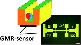
A transfer printing process is developed for thin film systems using a new type of water-soluble sacrificial layer – uncured polyvinylpyrrolidone (PVP). The bio-compatible PVP has a dual function, acting as both a buffer and a water-soluble sacrificial layer. Compared with the direct deposition of PyCu Giant Magneto-resistance (GMR) sensors onto bio-relevant, thermoplastic and flexible PEEK foils, the sensitivity of sensors transferred onto PEEK from a PVP-buffered Si substrate is raised from 4.1 T−1 to 30.8 T−1 and the GMR ratio is raised from 2% to 12%. This means that comparable values were achieved and sometimes even exceeded on Si substrates. The performance enhancement is proved to be the result of the decoupled arrangement of the substrate material and the tailored mechanical stress state. The transfer process developed is of a general nature and can be applied to other thin film systems and complete electronic components. The transferred sensors are used to count magnetically functionalised containers consisting of Fe-filled carbon nanotubes in a polymeric matrix. A detection rate ≥91% was achieved.

Introduction

The stated long-term goal is to manufacture and use magnetically functionalized, biocompatible micro- and nano-containers with customised properties and a defined effect achieved by adding agents such as therapeutic or diagnostic agents. In this concept, magnetically functionalized carbon containers are realized by the in situ growth of ferromagnetically filled carbon nanotubes acting as carbon-protected micromagnets.1–3 The magnetic filling has a dual function. On one hand it is needed for a hyperthermal effect to raise the temperature by means of a changing magnetic field in therapeutic applications,4 on the other it opens up the new possibility of counting the number of containers using magnetic sensors. The sensor performance is only important in the low magnetic field range because of the low magnetic field generated by the functionalized micro-containers. Due to increased sensitivity in the target field range, GMR sensors based on permalloy (Ni80Fe20) and copper are preferred for such applications, with layers coupled at the 2nd antiferromagnetic maximum.

In the specific case of biomedicine application, only single-use sensors are employed. If these sensors are to be widely used, they thus need to be inexpensive to manufacture. Flexible, polymer-based single-use structures, which have until now rarely been used, could be an alternative. The overall concept is set out in Fig. 1. The main components of this construction element are the polymeric polyether ether ketone (PEEK) foil, the geometrically adapted fluidics structures in that substrate, the magnetic sensors and the multi-functional micro-container. The principle of electrical measurement is shown in Fig. 1b. The resistivity of the GMR sensor is reduced when a magnetically functionalized micro-container passes the sensor detection area. The resulting voltage difference is recorded as a constant current is applied.


image file: c5ra05966f-f1.tif
Fig. 1 Schematic diagram for mechanical arrangement (a) and electrical measurement (b) of the system. Sensor is placed on the bottom side (c).

PEEK substrate is preferred due to the fact that it is verifiably biocompatible and autoclavable and thus it is frequently used in biological and biomedical applications.5,6 Furthermore, PEEK is flexible, with remarkable toughness and stiffness, and thus the geometry can be changed after the sensor production process.

In the present work we focus on creating a GMR sensor – one of the key components in the above concept – based on PyCu on preferred polymeric substrates, and on proving in principle that the system is operable using test containers. Pre-tests have found that when they are directly deposited on PEEK foils, PyCu multilayers only have a maximum GMR ratio of about 2% under the best optimized deposition conditions. This is due to the well-known fact that substrate quality has a decisive role on the properties of deposited GMR sensors and PEEK is a representative of polymeric substrates with a high roughness. These GMR values are not sufficient for focused use and thus the challenge is to reveal a means of significantly raising these values and attaining the values known to be achievable for sensors which are made on the basis of Si/SiO2 or glass substrates. For this purpose, a transfer process is to be developed which can be put into more general use.

The literature describes a whole series of different techniques for transfer printing.7–18 There are two kinds of techniques for transfer with and without a sacrificial layer. For transfer printing without sacrificial layers, polydimethylsiloxane (PDMS) is often used as a stamp and the transfer mechanism is based on kinetically controlled switching between the adhesion and release of solid objects to and from an elastomeric stamp.18 This process has evolved into one of the most interesting and often used-technologies for transferring structures onto hydrophilic or hydrophobic surfaces. It is used not only to transfer lithographically defined patterns, but also for other types of materials, e.g. nanowires.19 The main challenge of this process is optimizing the delamination speed and tailoring the surface properties, especially those of the acceptor substrate.

The other technique is to use a sacrificial layer. Certain sacrificial layers are based on GaAs compounds, but acids are often used to remove them and thus this is not applicable for transferring metallic multilayers. A very promising alternative is the use of polymeric materials. D. H. Kim et al. used polymethyl methacrylate (PMMA) as a sacrificial layer,14 but used acetone to dissolve the sacrificial layer, which is not applicable for all kinds of polymeric receiver substrates. The ideal solution appears to be to use ubiquitous solvents such as water. S. H. Kim et al. have developed a technology by means of which water-soluble sacrificial layers made of polyacrylic acid (PAA) or dextran are used,17 though the sacrificial layer is not used to transfer the structures; instead it separates the donor substrate from the flexible receiver substrate, such as a very thin PET foil. Thus the sacrificial layer in fact serves to mechanically fix the thin PET substrate in place during processing. The experiments on the use of PAA trace back to Linder et al.,20 who used PAA as a water-soluble sacrificial layer in surface micromachining processes. Of the water-soluble sacrificial layers investigated, only PAA met the requirements for use in conventional thin-film technology. A temperature range of 95–100 °C is recommended to remove the sacrificial layer in water. When the PEEK substrate material we prefer is used, this temperature range cannot be applied, as it is a thermoplastic material whose geometry changes at such temperatures, especially in the case of the μm-wide channels. Linder et al. also indicate that Al layers do not adhere well to the sacrificial layer they used, and form flakes when combined with water. As aluminium is a standard material for bonding magnetic structures and sensors, PAA does not seem suitable for use as a sacrificial layer. A remarkable step forward in using a water-soluble sacrificial layer was made by Yim et al.21 Poly(sodium 4-styrene sulfonate) (PSSNa) was used to overcome the solvent-compatibility issue in the fabrication of multilayered conjugated-polymer structures and the transfer printing of metallic contacts using PDMS stamps. They used this technique to produce light-emitting diodes and photovoltaic cells. In pre-experiments PSSNa was used in the fabrication of GMR sensor structures. Unfortunately the sensor properties achieved were limited to a few percent.

There are important studies by Chen et al. concerning the influence of the surface roughness of polymeric layers on the GMR effect.22,23 As shown from the example of a CoCu system, Si substrates buffered with photoresist can achieve a higher GMR effect than on pure Si. This raises the hope that the GMR effect can be partly disassociated from the substrate type and that there might be a possibility of developing a selective transfer printing process. However, this photoresist was not used as a sacrificial layer but as a buffer layer. Following Kim et al.'s idea of using PMMA, it is a small step to use the described photoresist as a sacrificial layer.14 Unfortunately, this photoresist is also not water soluble and the CoCu coating system demonstrates its insufficient sensitivity in the lower magnetic field range. These results have not yet been confirmed for the PyCu system.

In summary, we have to conclude that there is currently no suitable sacrificial layer for the application at the focus of our work. Moreover, when depositing magnetic functional layers, the polymer layer has to fulfil a crucial dual role. As well as acting as a sacrificial layer, it also has to act as a buffer layer and is not allowed to have any negative effect on the GMR properties of the layers deposited. Until now there has been no description of a dual function of this kind in the literature. The sacrificial/buffer layer was to have the following properties: (1) water soluble at room temperature. (2) Metal layers to adhere well directly to the polymeric buffer/sacrificial layer. (3) Low roughness to achieve higher GMR effects. (4) Resistance to the solvents used in subsequent technological processes. (5) Easily removable to allow layers to be transferred over a large area. (6) Sacrificial layer must be distributed on the donor substrates uniformly and in a single phase.

The aim of our experiments is to use alternative, water-soluble polymer layers on any donor substrates to create PyCu GMR layers with sufficient sensitivity and to transfer the layers onto receiver substrates (e.g. PEEK), retaining the good sensor qualities to a great extent. An additional requirement arising from the study by Linder et al. is that both aluminium layers and metal layers in general need to adhere sufficiently well to the water-soluble sacrificial layer.20 Furthermore, fluidic structures are to be generated using PEEK and used in combination with the sensor to count magnetically functionalised test containers.

Results and discussion

1. Developing the transfer process

In an initial series of experiments the GMR multilayers were directly deposited on the substrate by means of conventional magnetron sputtering, with the layer thicknesses and numbers of multilayers selected in the range of the second antiferromagnetic maximum. Specifically, 35 multilayers of Py (1.5 nm) and Cu (2.2 nm) were deposited. The measuring structures used are set out in Fig. 2. The upper part of the Fig. 2 shows the geometry for lithographically defined arrangements, with the width of the resistive tracks varying within a framework of 1 μm, 10 μm, 100 μm and 1000 μm. To study the possible damaging influence of the chemicals used during the structuring process, experiments were also carried out using metallic shadow masks as shown in the lower part of the Fig. 2. These different layouts were selected so that each technology could be recognized immediately from the structures used. For the 1000 μm width range, the length/width ratio, which is crucial for sensor resistance, is always 5[thin space (1/6-em)]:[thin space (1/6-em)]1. This was taken into account in both versions.
image file: c5ra05966f-f2.tif
Fig. 2 Optical microscopy image of measurement structures. The upper part of the figure represents the sample fabricated by optical lithography and ion beam etching (width of central line 1 μm, 10 μm, 100 μm, or 1000 μm), scale bar represents a length of 200 μm, the next part of the figure represents the sample fabricated by metallic shadow masks (width of central line 1000 μm).

The electrical resistance was determined using a conventional 4-point measuring system with a Keithley 238 constant-current source and a Keithley 182 nanovolt meter. A computer-controlled electromagnet was used to realize an external magnetic field. The GMR ratio is defined as the magnetic-field-dependent change in the sample resistance of R(Hext), normalized to the resistance of the magnetic field saturated sample of Rsat: GMR(Hext) = [R(Hext) − (Rsat)]/Rsat, the sensitivity is defined as the first derivative of the sample resistance over the magnetic field divided by the resistance value: S(Hext) = [dR(Hext)/dHext)]/R(Hext). While the measured GMR effects for glass and the Si substrate were within the range known from the literature for PyCu, at 15% and 14%,24,25 the values were unexpectedly low for polyimide (DuPont Kapton® HN30) foil (10%) and (PTFE, Teflon®) foil (8%), as well as for the PEEK foil (preferred for its favourable properties), whose value was just 2% as shown in Fig. 3. We explain this reduction in the effect as resulting from the different surface quality, and thus the different magnetic coupling conditions, as well as the different levels of layer growth. As mentioned before, PEEK is an example for all polymeric substrates representing a high surface roughness. The differences in the degree of roughness were characterized using AFM technology.


image file: c5ra05966f-f3.tif
Fig. 3 GMR ratio of PyCu structures, deposited and structured on different type of substrates: (i) PEEK foil; (ii) PTFE foil; (iii) polyimide foil; (iv) Si/SiO2; (v) glass.

The search for suitable sacrificial layers reveals that some polymeric layers have particularly favourable properties. One typical example is poly (n-vinylpyrrolidone) (PVP). This is a frequently used polymer which is, for example, also used to promote the adhesion of glass, metals and polymers. As an amorphous material, it forms smooth layers. It should be pointed out that PVP can appear on a substrate in differing states. The most important state for this study is the dry layer of uncured polymer (PVP-u). When this layer is crosslinked, its water solubility is lost (PVP-cl) and if water is absorbed a hydrogel (PVP-hg) is formed. Using these differences in a targeted manner allows the polymer to be used as an easily soluble sacrificial layer in a transfer printing process. PVP is an additive (E1201) used in the food industry, meaning that it is biocompatible and cannot leave any toxic residues. Moreover, neither the substrate nor the layers can be affected due to water solubility.

Fig. 4 is a diagram of the transfer process used. After the donor substrate was coated with PVP-u and the necessary drying process was carried out at 60 °C for 12 h, the magnetic multilayer system was deposited by conventional magnetron sputtering and the geometry required was created using photolithography and Ion Beam Etching (IBE). The desired receiver substrate, e.g. a PEEK foil, was coated with a suitable adhesive, e.g. an epoxy resin (DELO-KATIOBOND® KB554,26) pre-activated by UV light and the two substrates were joined. After that, the composite was placed in water. There is a wide range for the water temperature (0.5–100 °C). This temperature determines the time for the solving process. The water dissolved the uncured PVP and the structure no longer adhered to the donor substrate and finished the transfer process as shown in 9 of Fig. 4. In principle, further layers can be deposited and structured, e.g. a contact system and interconnects. Our own experiments involved both transferring geometrically well-defined structures and transferring complete, extensive layers then structuring them on the receiver substrate (see “transfer GMR layers” section in ESI). No differences were found in the level of the GMR effect depending on the type of process.


image file: c5ra05966f-f4.tif
Fig. 4 Schematic diagram of transfer printing process. (1) Cleaned donor substrate (ds), e.g. Si; (2) ds, deposited with PVP as sacrificial layer; (3) ds, deposited with GMR multilayer; (4) ds, pattern GMR multilayer into desired geometry by conventional optical lithography and ion beam etching with the following purification; (5) cleaned receiver substrate (rs), e.g. PEEK-foil; (6) rs, fabrication of channel structures by optical lithography and wet-chemical etching; (6c) rs, cross-section view, fluidic channel structure is visible; (7) rs deposited with epoxy onto opposite side of fluidic channel; (8) side view of assembled ds and rs; layer stack: ds/PVP/GMR/epoxy/rs with channel; (9) ds and rs separated by solving of PVP in pure water, transfer is realized; (10) ds ready for recycling to use it in a next run; (11) transferred GMR sensor on rs, pattern was mirror inverted to the y axis (compare 4 and 11); (11c) rs, cross-section view, layer stack: sensor/epoxy/rs with fluidic channel.

Fig. 5 shows examples of transferred structures. A detail is shown of the letters “AP” containing resolution test patterns and corresponding to the letters “AP” in the upper part of the Fig. 2. Note that the transfer flips the structures on their y axis. The smallest structures transferred are 900 nm in width for lines and 950 nm in diameter for circular structures. However, this size is not the limit; it is caused by the resolution of the optical lithography used to create the photoresist structures.


image file: c5ra05966f-f5.tif
Fig. 5 Optical microscopy image of transferred structures, realized structures are down to μm-scale (details of characters “ap” visible in the center part of the upper part of the Fig. 2 are mirrored to y axis by transfer process), scale bar represents a length of 50 μm.

As mentioned in the introduction for the CoCu system reported by Chen et al.,22,23 Si substrates buffered with photoresist can achieve a higher GMR effect than on pure Si and this result has not yet been confirmed for other systems, the GMR effect of PyCu sensor on PVP-buffered Si substrates was determined to study how the PVP layer can influence PyCu performance. The positive result achieved by Chen et al. on the CoCu system was confirmed for the PyCu system. The GMR effect was shown to be raised slightly, but significantly, at 0.4% (overall effect of 15.3%), making it relatively somewhat lower than the effect shown by Chen et al. on the CoCu system with photoresist buffering at high multilayer numbers (about 1.3% with a 33% overall effect). This means that PVP is a suitable buffer layer material.

The transfer process described was used to transfer GMR structures from PVP-u buffered donor substrates to a wide range of receiver substrates, such as PEEK foil. Fig. 6 shows the measured performance of the transferred sensor. Surprisingly, the shape of the GMR curve was changed slightly, and the degree of sensitivity in the low magnetic field range was changed considerably. Thus the sensitivity was raised from 20 T−1 to 30.8 T−1, i.e. by approx. 50% by the transfer process. In this process, the identical measurement structure was examined both before the transfer process (Si/PVP/GMR sensor) and after it (PEEK/epoxy/transferred GMR sensor), and thus this significant improvement cannot be explained by changes in the roughness with improved magnetic coupling (see also atomic force microscopy results in ESI). Several studies including Chen et al. also confirmed that the roughness of polymeric buffer layers or polymer films based on different materials is higher than that of Si substrates.23


image file: c5ra05966f-f6.tif
Fig. 6 GMR ratio (the upper part of the figure) and sensitivity (the next part of the figure) on PVP-u buffered Si (before transfer printing) and PEEK (after transfer printing). Same structure was measured before and after the transfer process.

Here we ascribe the improvement of the sensor performance to the altered mechanical state of stress in the multilayers caused by the dissolution of the donor substrate and the implemented mechanical stress by the epoxy resin. To determine the influence of mechanical stress on the level of the GMR effect and the shape of the GMR curves, mechanical stress tests were carried out. These involved fixing PyCu measuring structures with a chip size of 18 mm × 3 mm on oxidized Si using epoxy resin onto non-magnetic parent panels (Al) measuring 500 mm × 40 mm × 14 mm and firmly clamping this composite on one side by mechanical means. The other end was loaded with weights, so that from the point of view of mechanical stress, the well-defined setup was created as a “simply supported beam” as shown in Fig. 7.27 Using this setup, the GMR curves were determined when loaded with different weights depending on an external magnetic field. The force applied results in defined tensile or compressive stress depending on whether the sensor is fitted on the upper or lower side of the parent panel.


image file: c5ra05966f-f7.tif
Fig. 7 Arrangement of “simply supported beam” method to determine the influence of mechanical stress on GMR effect. The sample is placed on top side; a tensile stress is realized in this geometry by acting of force f, inserted (a) gives a top view of the mounted sample.

To investigate this dependence, the Si chip was fixed in place with the measuring structure on the Al cantilever. The current flows in the direction of the external magnetic field and the mechanical stress is applied diagonally to this, at a 90° angle. Under these conditions, the change in the resistance geometry (width) caused by the mechanical stress is negligible due to the length-to-width ratio.

To determine how the GMR effect is dependent on the mechanical stress, 50 g, 100 g, 220 g, 350 g, 450 g, and 550 g weights were attached to the free end of the cantilever (clamped on one side) and the resistance was measured depending on the external magnetic field. Reproducible, reversible changes were identified in the GMR dependence. The values for the initial condition for +4.4 N and for −4.4 N are shown as an example in the upper part of Fig. 8. All other values fit systematically into this dependence. It can be seen that tensile stress raises the resistance, while compressive stress reduces the resistance, with the same μ0Hext. Within the limits of measuring accuracy, the important extreme value R0 is not significantly changed with this measuring arrangement (the width of the resistive track is changed). However, metrological proof can be provided of a significant change in R0 if the mechanical stress acts in a parallel direction to the track, with a major change in the length-to-width ratio of 5[thin space (1/6-em)]:[thin space (1/6-em)]1 (the length of the track is changed) compared with the crosswise arrangement. As shown in the lower part of the Fig. 8, this altered state of stress also leads to a systematic change in sensitivity.


image file: c5ra05966f-f8.tif
Fig. 8 GMR effect (the upper part of the figure) and sensitivity (the next part of the figure) dependence on an outside force (PyCu structures on Si wafers). (i) before measurement; (ii) f = +4.4 N; (iii) without mechanical stress, after measurement of (ii); (iv) f = −4.4 N.

Based on the mechanical stress tests, we come to the conclusion that a defined state of stress sets in when the GMR multilayers are deposited onto Si. When the GMR multilayers are deposited onto buffer layers, the stress state is different as the soft polymer layers encourage in situ relaxation. This can be seen in the GMR and sensitivity curves on buffered polymer layers. An additional stress relaxation takes place and enhances the GMR effect when the sacrificial layer (PVP-u) is dissolved. The enhancement of this effect is combined with a change in the gradient of the curve recorded, meaning that the sensitivity can also be shown to be enhanced. If these layers are transferred to other substrates, attention should be paid to the properties of the adhesives. When an epoxy resin is used, e.g. Delo-Katiobond® KB554, the volume shrinks by 3–5% during hardening, causing compressive stresses to be transferred to GMR multilayers;28 as shown in the lower part of Fig. 8 this improves the sensitivity yet further.

2. Using the developed transfer process

2.1 The production of magnetically functionalized test containers. For calibration and to prove that the transferred sensor can operate satisfactorily for counting, it is necessary to produce suitable test compartments; fluorescence microscopy was selected as an independent counting method for comparison (see ESI).
2.2 Determining the number of functionalized containers. Once the PEEK channel structures were created and GMR sensors were transferred (see ESI), the aim was to determine the number of containers using two mutually independent methods as described above. The electrical signal of magnetically filled containers was measured using a Keithley 182 nanovolt meter and recorded using a computer, with a total of 4 GMR sensors in a Wheatstone bridge. The optical signal was counted manually from the fluorescence microscopy. For each series of measurements, 500 containers were used. Fig. 9 shows a section of one of the electrical detection curves recorded. This detection curve was selected as it demonstrates the possibilities and challenges. The different peak heights result from the different magnetic fillings of the test containers. However, the number of measuring points is also of extreme significance for mapping. To ensure that the peaks are determined correctly, several measuring points per peak need to be determined. Peak no. 1 in Fig. 9 can be seen as an example. Here, 3 measuring points can be seen on the slope and 3 around the minimum. This can be achieved by improving measuring conditions or optimizing the flow speed in the channels. A comparison of the two methods shows that when optimal measuring conditions are attained, approximately 91% agreement between the two methods can be achieved.
image file: c5ra05966f-f9.tif
Fig. 9 Electrical measurement (counting) of magnetic functionalized microcontainers in a fluidic system, using PEEK as substrate.

Conclusions

During the study a new transfer process was developed for electrical and magnetic thin film systems using water-soluble, uncured polyvinylpyrrolidone (PVP-u). The PVP has a dual function, acting both as a buffer and as a water-soluble and bio-compatible sacrificial layer. Thanks to its function as a buffer layer, using PVP can minimise the influence of the substrate material to a critical extent, significantly improving the sensor properties. Even when buffered Si substrates are used, the GMR effect can be significantly increased. Compared with the direct deposition of the PyCu GMR coating system, with a layer thickness being applied at the second antiferromagnetic maximum on biorelevant and flexible PEEK foils, the level of the layers' GMR effect was raised from 2% to 12% and the sensitivity from 4.1 T−1 to 30.8 T−1. This means that comparative values were achieved and sometimes even exceeded on Si substrates. The performance enhancement is proved to be the result of the tailored mechanical stress state. The transfer process developed is of a general nature and can be applied to other thin film systems, complete electronic components and other donor substrates too. The process described can be used for transferring both individual structures and extensive films. The line width of the smallest structures transferred was about 900 nm, but this value is not a limit. The transfer process developed was used to produce sensor elements on PEEK foils. These elements were used to count magnetically and optically functionalized test containers consisting of Fe-filled CNTs and photoresist composite. A detection rate ≥91% was achieved.

Acknowledgements

The National Natural Science Foundation of China (Grant No. 11175242) is acknowledged for financial support.

References

  1. B. Zhao, R. Kozhuharova, T. Muehl, I. Moench, H. Vinzelberg, M. Ritschel, A. Graff, M. Huhle, H. Lichte and C. M. Schneider, XVI International Winterschool on Electronic Properties of Novel Materials, Kirchberg/Oesterreich, AIP Conf. Proc., 2002, 633, 583–587 CrossRef CAS PubMed.
  2. A. Leonhardt, A. Ritschel, R. Kozhuharova, A. Graff, T. Muhl, R. Huhle, I. Moench, D. Elefant and C. M. Schneider, Diamond Relat. Mater., 2003, 12, 790–793 CrossRef CAS.
  3. I. Moench, A. Meye, A. Leonhardt, K. Kramer, R. Kozhuharova, T. Gemming, M. P. Wirth and B. Buechner, J. Magn. Magn. Mater., 2005, 290, 276–278 CrossRef PubMed.
  4. I. Moench, A. Meye and A. Leonhardt, in Nanomaterials for Cancer Therapy, ed. C. Kumar, WILEY-VCH, 2006, vol. 6, pp. 259–337 Search PubMed.
  5. H.-D. Jung, H.-S. Park, M.-H. Kang, S.-M. Lee, H.-E. Kim, Y. Estrin and Y.-H. Koh, Mater. Lett., 2014, 116, 20–22 CrossRef CAS PubMed.
  6. S. M. Kurtz and J. N. Devine, Biomaterials, 2007, 28, 4845–4869 CrossRef CAS PubMed.
  7. E. Menard, L. Bilhaut, J. Zaumseil and J. A. Rogers, Langmuir, 2004, 20, 6871–6878 CrossRef CAS PubMed.
  8. E. Menard, K. J. Lee, D. Y. Khang, R. G. Nuzzo and J. A. Rogers, Appl. Phys. Lett., 2004, 84, 5398–5400 CrossRef CAS PubMed.
  9. Y. G. Sun and J. A. Rogers, Nano Lett., 2004, 4, 1953–1959 CrossRef CAS.
  10. K. J. Lee, M. J. Motala, M. A. Meitl, W. R. Childs, E. Menard, A. K. Shim, J. A. Rogers and R. G. Nuzzo, Adv. Mater, 2005, 17, 2332 CrossRef CAS PubMed.
  11. E. Menard, R. G. Nuzzo and J. A. Rogers, Appl. Phys. Lett., 2005, 86, 093507 CrossRef PubMed.
  12. Y. Sun, H.-S. Kim, E. Menard, S. Kim, I. Adesida and J. A. Rogers, Small, 2006, 2, 1330–1334 CrossRef CAS PubMed.
  13. Z. T. Zhu, E. Menard, K. Hurley, R. G. Nuzzo and J. A. Rogers, Appl. Phys. Lett., 2005, 86, 133507 CrossRef PubMed.
  14. D.-H. Kim, J.-H. Ahn, W. M. Choi, H.-S. Kim, T.-H. Kim, J. Song, Y. Y. Huang, Z. Liu, C. Lu and J. A. Rogers, Science, 2008, 320, 507–511 CrossRef PubMed.
  15. D.-H. Kim, J. Viventi, J. J. Amsden, J. Xiao, L. Vigeland, Y.-S. Kim, J. A. Blanco, B. Panilaitis, E. S. Frechette, D. Contreras, D. L. Kaplan, F. G. Omenetto, Y. Huang, K.-C. Hwang, M. R. Zakin, B. Litt and J. A. Rogers, Nat. Mater., 2010, 9, 511–517 CrossRef CAS PubMed.
  16. K. J. Lee, H. Ahn, M. J. Motala, R. G. Nuzzo, E. Menard and J. A. Rogers, J. Micromech. Microeng., 2010, 20, 075018 CrossRef.
  17. S. H. Kim, J. Yoon, S. O. Yun, Y. Hwang, H. S. Jang and H. C. Ko, Adv. Funct. Mater., 2013, 23, 1375–1382 CrossRef PubMed.
  18. M. A. Meitl, Z. T. Zhu, V. Kumar, K. J. Lee, X. Feng, Y. Y. Huang, I. Adesida, R. G. Nuzzo and J. A. Rogers, Nat. Mater., 2006, 5, 33–38 CrossRef CAS PubMed.
  19. X. Zhou, Y. Zhou, J. C. Ku, C. Zhang and C. A. Mirkin, ACS Nano, 2014, 8, 1511–1516 CrossRef CAS PubMed.
  20. V. Linder, B. D. Gates, D. Ryan, B. A. Parviz and G. M. Whitesides, Small, 2005, 1, 730–736 CrossRef CAS PubMed.
  21. K.-H. Yim, Z. Zheng, Z. Liang, R. H. Friend, W. T. S. Huck and J.-S. Kim, Adv. Funct. Mater., 2008, 18, 1012–1019 CrossRef CAS PubMed.
  22. Y. F. Chen, Y. F. Mei, R. Kaltofen, J. I. Monch, J. Schumann, J. Freudenberger, H. J. Klauss and O. G. Schmidt, Adv. Mater, 2008, 20, 3224 CrossRef CAS PubMed.
  23. Y. F. Chen, Y. F. Mei, A. Malachias, J. I. Moench, R. Kaltofen and O. G. Schmidt, J. Phys.: Condens. Matter, 2008, 20, 452202 CrossRef.
  24. S. S. P. Parkin, Appl. Phys. Lett., 1992, 60, 512–514 CrossRef CAS PubMed.
  25. W. Ricken, J. Liu and W. J. Becker, Sens. Actuators, A, 2001, 91, 42–45 CrossRef CAS.
  26. Products Data Sheet DELO Katio Bond KB554, http://www.delo.de, 2014.
  27. M. Stein, J. App. Mech., 1989, 56, 228–231 CrossRef.
  28. Company information, DELO Industrial Adhesives 86949 Windach, Germany.

Footnote

Electronic supplementary information (ESI) available. See DOI: 10.1039/c5ra05966f

This journal is © The Royal Society of Chemistry 2015
Click here to see how this site uses Cookies. View our privacy policy here.