
Magnetically driven superhydrophobic meshes with the capacity of moving at air/water and oil/water interfaces†
Jihua Zhang *a,
Huadong Fenga,
Weitao Zaoa,
Yunfeng Zhaoa,
Hui Zhang*bc and
Yibin Liub
*a,
Huadong Fenga,
Weitao Zaoa,
Yunfeng Zhaoa,
Hui Zhang*bc and
Yibin Liub
aAerospace Research Institute of Material and Processing Technology, Beijing 100076, P. R. China. E-mail: zjhicca@iccas.ac.cn
bSchool of Materials Science and Engineering, Tsinghua University, Beijing 100084, P. R. China
cInstitute of Chemistry, Chinese Academy of Sciences, Beijing 100190, P. R. China
First published on 11th May 2015
Abstract
The hazard of oil contamination in sewage detection has drawn great attention and gives rise to some technical difficulties for pipe inspection applications using robots. In the attempt to face this challenge, a magnetically controlled micro-robot model was designed to allow it to move directionally on oil-contaminated water. In this design, magnetically responsive mesh supports were used; moreover, these were required to float at air/water and oil/water interfaces. Optimal analysis of force shows the importance of superhydrophobicity for the floatability of mesh supports at these two interfaces. Accordingly, mesh surfaces were decorated to produce superhydrophobicity by a simple fluorination process. A superhydrophobic mesh was experimentally verified to freely float at both interfaces, providing a large supporting force to improve its floating stability. Guided by a magnetic field, the micro-robot model with mesh supports could float, move and rotate at air/water and oil/water interfaces in a closed system. Therefore, our findings could offer guidance for the design of aquatic micro-devices to detect sewage in bent or small-sized pipes.
Introduction
Sewage has attracted more and more attention due to it harming the health and life environment of human beings.1 To prevent pollution hazards, wastewater treatment, the process of removing contaminants from wastewater, has been developed.2 By applying this technology, plants can produce an environmentally safe fluid waste stream or solid wastes suitable for disposal or reuse. In contrast with soil particles and other waste, disposal of wastewater from an industrial plant is a difficult and costly process, especially for oil and grease from most petroleum refineries, chemical and petrochemical plants.2,3 To deal with this problem, networks of pipes and pumping stations have been constructed to collect and transport oil-polluted sewage to a centralized system. However, pipeline corrosion, aging, obstruction or leakage often cause secondary environmental pollution. Therefore, pipeline inspection has become a frequent task. Instead of manual operations, large and complex robots have been invented to check the flow of wastewater. If wastewater has leaked or is blocked up, they are able to detect these situations and even help the cleaning, repair and maintenance of the pipeline by wire or remote control.4 However, their large bodies equipped with CCD cameras and sensors lose the capacity to traverse across the vertical parts of pipelines or small-sized pipes.5–7 Also, extra power is required to enable robots to walk along the slippery interior of pipes, which causes difficulties for long-distance inspections. This situation severely restricts robot applications. It has become an emergency need to develop smart micro-robots to check complex pipelines.Recently, some interesting devices for the clean-up of oil spills at oil/water interfaces have caught our attention.8–10 Researchers introduced magnetically responsive materials and then applied a magnetic field to drive them to collect oil from the water surface or underwater.9,10 Shi et al. designed a functionally integrated device to collect spilled oil into magnetically driven floating foam and then pump it away.10 Due to the penetrating ability of the magnetic field, the device still worked when it was placed into a closed system. This enlightened us: in the same way, a magnetic field could be used to control the movement of micro-robots to detect oil-contaminated sewage in a closed pipeline. However, to simultaneously control the floating of a micro-robot and drive its movements are always complex operations for an applied magnetic field. One of the best strategies is to design a magnetically responsive robot that always floats on a water surface (whether it is polluted by oil or not). A magnetic field is only employed to actuate floating micro-robots to move or make a turn on the water during the inspection. Moreover, the capacity of micro-robots to be supported on water should be as large as possible, which not only allows them to carry more inspection equipment but also improves the moving stability of the robot along the water, guided by magnetic attraction. Therefore, we believe that to fabricate magnetically driven micro-robots with a large floating capacity on water is important for applications in pipe inspection.
The floating problems of micro-robots in the air seem to be solved by using superhydrophobic “legs” or supports, which creates some hope of applying them in pipe detection. Up to now, superhydrophobic legs or surfaces have been synthesized by lithography, phase separation, templating, etching, sol–gel, solution immersion, electrospinning, chemical vapour deposition, spin-coating/dip-coating, electrodeposition and spray techniques, which provide a combination of micro/nano hierarchical or nanoscale structures and low surface energy with a high contact angle of greater than 150°.11–14 By utilizing these legs, micro-robots can float on the water surface but not penetrate it.15–20 However, most of them are unable to move on water and so cannot meet the needs of real applications. Moreover, they generally suffer from low durability due to the mechanically fragile micro/nano structures on the superhydrophobic legs.11 It has also been found that, although hierarchical roughness covered with a low-surface-energy layer has attracted a lot of attention for improving the mechanical durability of superhydrophobic supports,13 degradation of the low-surface-energy layer and damage to the nanoscale roughness can result in a loss of superhydrophobicity.11 Therefore, it is important to apply a proper processing method to prepare a suitable superhydrophobic structure in order to satisfy the durability requirements in aquatic applications. On the other hand, these micro-robots frequently do not work when in contact with an oily liquid, especially an oil/water mixture. The low oil/water interface tension and oleophilic properties of materials always decrease their floating ability. This generates some technology concerns for micro-robots when they float on water to check oily contaminants in closed pipelines. They would easily fall in the water and are not able to contact these pollutants. Therefore, there are still new challenges in making special supports that can move on an oil-polluted water surface to assist micro-robots.
In this article, we have designed a magnetically controlled micro-robot model for pipe detection. To maximize the supporting force of the floating model, an optimization analysis was first proposed. Accordingly, we prepared lightweight, magnetically responsive superhydrophobic meshes by introducing the materials of iron alloy, proper mesh structures and a low-surface-energy fluorinated coating. Ferrous mesh possesses high water repellency both in air and under oil. Moreover, its structure without nanoscale roughness avoids wear damage of water to its superhydrophobicity, which is suitable for long-term floating applications. By using these meshes as supports, a floating micro-robot model was fabricated. In order to simulate real applications, the model was driven to stably move or rotate at two interfaces under a magnetic field while it was kept in a closed system. This model design provides a novel solution for fabricating a dynamic micro-robot to inspect oil-contaminated wastewater in a closed system. It would lead to promising applications in sewage inspection.
Optimizing aquatic supports to maximize the supporting force
Here, a simple circular plate support is modeled. For such a plate, force analysis is applied to show how one can achieve a maximum supporting force on water. Consider the floating plate illustrated in Fig. 1. Three types of forces are in play: a gravitational force (Fg), a buoyancy force (Fb) and a capillary force (Fc). The gravitational force is directed downward and is constant for a plate of a given weight (mplate): Fg = mplateg. The buoyancy force is directed upward and depends on the volume of displaced liquid. The capillary force varies between up and down directions depending on the inherent wettability of the plate, as measured by the contact angle θ, and the position of the contact line on the plate.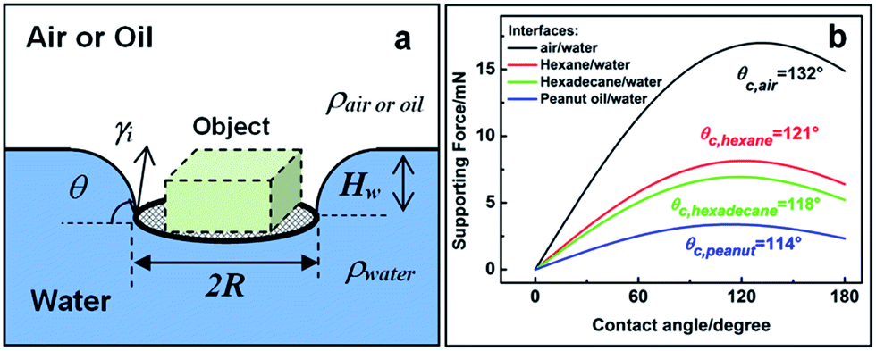 | ||
| Fig. 1 (a) Schematic diagram of a round plate floating at air/water or oil/water interfaces. (b) The plots of supporting force versus contact angle (θ) at air/water and oil/water interfaces for a plate with radius (R) of 10 mm. There is always a peak in the supporting force at a certain contact angle (i.e. the critical θc). | ||
The vertical component of the capillary force can be estimated from the radius of the plate R, the interface tension of the liquid γi, and the θ value of the liquid on the plate surface:21
Fc = 2πRγi![[thin space (1/6-em)]](https://www.rsc.org/images/entities/char_2009.gif) sinθ. sinθ.
| (1) |
Buoyancy forces are equal to the sum of the atmospheric and hydrostatic pressures acting on the plate surface, which depends on the density of the liquid in air (or difference in density Δρ between oil and water), the radius of the plate R and the depth of water (Hw) above the plate:22
| Fb = πR2ΔρgHw. | (2) |
Extrand et al. deduce the Hw value at a two-phase interface:23
 | (3) |
Therefore the floating plate can provide a supporting force, Fsupporting, which is equal to the difference between the upward and downward forces:
| Fsupporting = Fc + Fb − Fg. | (4) |
Combining eqn (1)–(4) produces an expression for estimating the value of Fsupporting:
 | (5) |
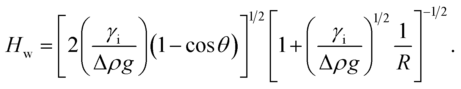
Apparently, it can be deduced from eqn (5) that the larger the values of R, Δρ, and γi are, the larger Fsupporting is. However, the effects of the wettability of the plate surface on Fsupporting are complex: with an increase in the value of θ, Fc increases and then decreases, as a sinusoidal function; on the other hand, Fb increases monotonically when θ rises from zero to 180°. There is therefore always a peak value of Fsupporting at a critical angle of θc. Take the example of a plate with a radius of 10 mm to illustrate the effects of wettability on the value of Fsupporting. The relationship of Fsupporting versus θ at air/water and oil/water interfaces are plotted in Fig. 1b. Various physical parameters of oil and water are listed in Table S1.† In the case of the hexane/water interface, Fsupporting of the plate reaches a maximum value (∼8.15 mN) when the contact angle is about 121° (i.e. the critical θc). This means that the plate is able to exert its maximum supporting force if its contact angle is greater than θc.
Generally speaking, the interface environment is given and therefore its physical properties (i.e. Δρ and γi) are almost constant. However, it is inferred from eqn (5) that the weight of the plate mplate should be as little as possible in order for it to stably float. A thin plate with low density, such as porous sponge, metal meshes or paper, is preferred. Moreover, on the plate surface, high water repellency (i.e. a high contact angle) is always conducive to producing a maximum supporting force at air/water and oil/water interfaces. In addition, the plate support should be larger (i.e. increasing R or prolonging the contact line around the plate by varying the appearance of the edge) within the acceptable limits of micro-robot design.
Materials and methods
Sample preparation
Iron meshes were purchased from Haver & Boecker Wire Weaving Division, Germany. Three meshes were used, of which the wire diameter was fixed at 25 μm. The size of the quadratic pores was 25 × 25 μm, 56 × 56 μm and 100 × 100 μm, respectively.The meshes were cut into circular plates with scissors and were then ultrasonically washed in benzene, acetone, alcohol, and Milli-Q water for about 15 min, respectively. The samples were dried using N2 gas and immediately immersed in a 1.0 wt% ethanol solution of hydrolyzed heptadecafluorodecyltrimethoxysilane (FAS-17, CF3(CF2)7CH2CH2Si(OCH3)3, Shin-Etsu Chemical Co., Ltd., Japan) for 3 h at room temperature.24 Finally, the FAS 17-modified samples (FAS-mesh) were taken out to be heated at 140 °C in an oven for 1 h.
Instruments and observation
The morphology of the uncoated and FAS 17-modified meshes was characterized via scanning electron microscopy (SEM, SU8000, Hitachi, Japan). The surface chemical components were analysed using an X-ray photoelectron spectroscope (XPS) (ESCALAB 250, Thermo Corp., USA) equipped with standard monochromatic Al Kα radiation; the test depth was ∼3 nm. Static contact angles were obtained from side profile images of a 4 μL droplet using a DataPhysics OCA10 with video profilometry and drop shape analysis software (DataPhysics Instruments GmbH, Germany). The supporting force of meshes at air/water and oil/water interfaces was measured by dynamic contact angle measurement (DCAT 11, DataPhysics Instruments GmbH, Germany). (1) In air, the FAS-mesh was first hung on a microbalance by attaching it to a punch. It moved downward at a speed of 0.05 mm s−1 until its surfaces were completely immersed in water at a certain depth. Afterward, the mesh was elevated to its initial position. (2) At an oil/water interface, the FAS-mesh was placed on the oil surface. It sank and then floated at the oil/water interface. The supporting force of the mesh was tested by similar steps to those carried out in air. All test processes and the collection of data were automatically controlled using the software SCAT12 (version 1.01).Results and discussion
Fig. 2a shows the schematic structure of the metal mesh. Clearly, the mesh microstructure can be well controlled via the wire fiber diameter (d) and weave space between fibers (w). Three kinds of mesh were used in the experiments by varying the value of w: 25 μm, 56 μm and 100 μm. Fig. 2b and c show representative SEM images of uncoated mesh and FAS-mesh, respectively, with w = 100 μm. Note that the uncoated mesh fibers are almost smooth. Moreover, its plain-weave structures are uniform. Moreover, there are barely any differences in morphology for FAS-mesh. It is seen from the magnified inset of Fig. 2c that coating with FAS-17 does not cause any variations in topography on the fiber surfaces. To confirm that a FAS-17 coating was decorated on FAS-mesh, XPS measurements were conducted. Fig. 3 shows full spectra of uncoated mesh and FAS-mesh. The surface of uncoated mesh is composed of the elements Fe, C and O (corresponding to binding energies (BE) of 709.7 eV, 284.7 eV and 531.4 eV). Among these, the elements C and O mainly come from the compact passivated layer of uncoated mesh in order to provide corrosion resistance. After being coated by FAS-17, more elements were introduced to the FAS-mesh surface, including the elements F (BE = 688.6 eV) and Si (BE = 103.3 eV). The elemental content of Fe, C and O obviously decreases in contrast with uncoated mesh (see Table S2†). In the total elements, the contents of F and Si elements reach 22.5 wt% and 2.8 wt%, respectively. Besides, the ATR-FTIR spectrum of FAS-mesh was also examined in order to fully evaluate the chemical composition of the FAS-17 coating. However, the fluorinated coating was so thin that we cannot observe additional absorptions (for example, the absorption of the C–F group) for FAS-mesh than for uncoated mesh (see Fig. S1†). Nevertheless, a stable coating of FAS-17 has already come into being on the FAS-mesh surfaces.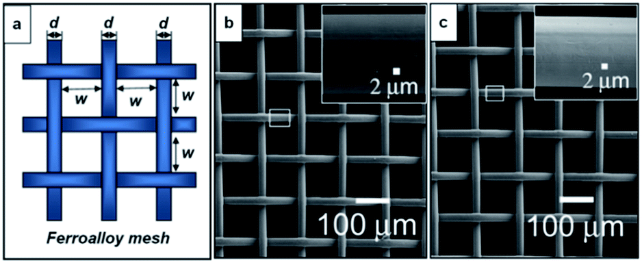 | ||
| Fig. 2 Morphologies of metal mesh: (a) schematic structure; (b and c) representative SEM images of uncoated and FAS 17-modified mesh with d = 25 μm and w = 100 μm. | ||
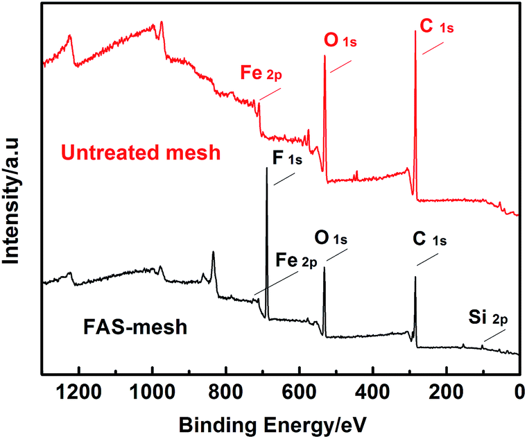 | ||
| Fig. 3 XPS spectra of uncoated mesh and FAS-mesh. | ||
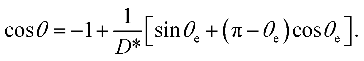
After examining the morphologies and chemical compositions, the contact angles of water droplets on FAS-mesh were tested in air. Note that they increase from 130.8 ± 1.5° to 139.3 ± 2.1° and 148.7 ± 1.2° with increases in w values in our cases (see ESI†). The contact angle is very close to 150° for the case with w = 100 μm, indicating its superhydrophobicity. After that, the contact angles of oily droplets such as hexane and hexadecane on FAS-mesh were determined. The ultra-low surface tension of an oily liquid in air brings about the remarkable oleophilicity of FAS-mesh. Complete wetting can be observed when a hexane droplet is deposited on the mesh. Conversely, after this mesh sank into an oily liquid, some larger water contact angles were observed. They are 155.2 ± 1.7°, 152.8 ± 1.3° and 168.1 ± 0.8° under hexane, hexadecane and peanut oil, respectively. Apparently, FAS-mesh possesses high water repellency in air and under oil. Besides, the droplets have very low hysteresis under oil (the rolling-off angle is below 5°) but they cannot fall off in air even when we turn over the mesh (see Fig. S2†). This indicates that FAS-meshes have different wettabilities in air and oil environments.
To reveal the mechanism of environment-induced variations in wettability, flat and smooth glass surfaces decorated by FAS-17 were used for comparison (see Fig. 4a). The conclusion is immediately drawn that the weave structures of the mesh surface give rise to its superhydrophobicity. However, it seems hard to understand how such a weave of micron scale can provide superhydrophobicity in air and under oil, instead of relying on micro/nano hierarchical structures or nanometer structures reported in the literature.15 To answer this question, Fig. 4b schematically shows the situation of a water droplet in contact with the mesh after it has been in the air or deposited under oil, where the local texture angle (ψ) represents the position of the contact line around a single mesh fiber. Although nanoscale rough structures are absent, the braided mesh can provide special surfaces with arrayed cylindrical fibers. When a droplet is deposited, the contact line encounters a steeper slope of cylindrical form and is then fixed at the location where the relation between ψ of mesh fibers and their intrinsic contact angle (θe) holds: ψ = θe. Because the value of θe on the mesh fibers is above 90° (i.e. ψ > 90°), the contact line of the droplet will overhang in the upper portion of its cylindrical feature and then the bottom of the droplet cannot penetrate into the spacing between arrayed mesh fibers. The situation of water in contact at such a composite interface can be interpreted by Cassie's model:25
|
cosθ = f1cosθe − f2,
| (6) |
 | (7) |
 | ||
| Fig. 4 (a) Contact angles of water droplets on smooth and FAS-mesh surfaces in air and under various oils. (b) Schematic diagram illustrating the water/air or water/oil interface on the textured mesh surface, where θe is the equilibrium contact angle and ψ is the local texture angle. Here, it is assumed that the deformation of the interface, which is caused by the pressure difference above the mesh fibers, is ignored due to the intrinsic hydrophobicity of FAS-mesh (θe > 90°). (c) The calculated plot of apparent θ versus equilibrium θe by eqn (7) and experimental comparisons. | ||
Fig. 4c shows the calculated plot of apparent θ versus intrinsic θe for the mesh with w = 100 μm. Clearly, growth in the intrinsic θe leads to an increase in the apparent θ for water. Therefore, arrayed cylindrical fibers provide re-entrant convex curvature to overhang the droplet and give rise to a simpler method of producing a large contact angle greater than 150° on the mesh than the traditional methods using micro/nano structures. There are a few errors between the calculated and experimental θ, which is ascribed to an inaccurate choice of the baseline of droplets on the mesh during contact angle measurements. On the other hand, the θe value of water under oil (hexane, hexadecane or peanut oil) is larger than that in air (see Fig. 4a), which implies a larger value of ψ under oil. Therefore, a water droplet is suspended at a location of a mesh fiber closer to its top. This shortens the length of the contact line, which causes smaller rolling-off angles of a droplet on the mesh under oils, rather than in air.
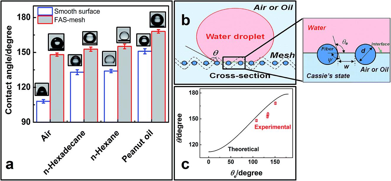
To the best of our knowledge, mechanical damage is always harmful to most applications of superhydrophobic materials.35–39 Similar technology concerns apply to our mesh. One non-standard abrasion test was performed by means of sand impacting to investigate its mechanical resistance (see Fig. 5a). Sand grains with a diameter of ∼300 μm impacted the mesh surface from a height of ∼40 cm. After testing for 5 min with sand abrasion, the contact angles were measured: 147.3 ± 0.9° and 152.1 ± 1.6° in air and under hexadecane, respectively (see Fig. 5b and c). These agree well with the initial contact angles in Fig. 4a. Therefore, the mesh retains its superhydrophobicity. After the abrasion test, the surface microstructures of FAS-mesh were also checked (see Fig. 5d). Its morphology hardly changed. Therefore, FAS-meshes were sufficiently robust to resist sand impacting.
 | ||
| Fig. 5 Mechanical resistance is examined by sand abrasion for 5 min. (a) Schematic of a sand abrasion experiment. (b and c) Optical images of a water drop being deposited on FAS-mesh when the mesh is in air and then sinks under hexadecane. (d) SEM image of FAS-mesh with w = 100 μm after sand abrasion. | ||
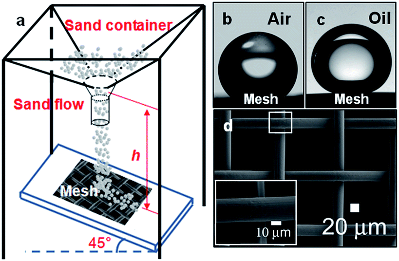
As described in eqn (5), a circular plate surface with a high contact angle above θc always provides a maximum supporting force on water. In other words, superhydrophobic meshes with contact angles of above 150° are destined to exhibit high supporting capacities in air or at an oil/water interface. To test such a large supporting force in air, a superhydrophobic mesh was slowly immersed in water by a circular piston (see Fig. 6a). At the same time, the shape of the water/mesh/air interface and the supporting force were recorded. When the mesh was gradually pushed into the water, the actual contact angle increased from zero to a critical angle (θair) of 150.2° at an immersed depth of Hw,air = 4.65 mm (see Fig. 6b) which agrees with the measurement of the apparent contact angle for a water droplet (148.7 ± 1.2°). After the mesh was pushed downward, the meniscus collapsed and then overflowed its top surface. Similar phenomena happened at oil/water interfaces. The critical angle of θoil at a hexane/water interface at which the meniscus collapsed is 158.3° (see Fig. 6c), which is close to the water contact angle (155.2 ± 1.7°) under hexane. The maximum immersed depths at air/water and hexane/water interfaces were measured as 4.5 ± 0.4 mm and 6.2 ± 0.3 mm, respectively. These agree with the values calculated by eqn (3) (see Fig. 6d).
 | ||
| Fig. 6 Measurements of immersed depth when the mesh is put into air/water and oil/water interfaces. (a) Schematic setup. (b and c) Critical optical images showing that the water meniscus collapses along the FAS-mesh surface at the critical θair and θoil, respectively. (d) Experimental and calculated data of meniscus immersed depths at various interfaces. | ||
Fig. 7a shows plots of supporting force versus immersed position at air/water and oil/water interfaces. When the mesh was pressed into water, the supporting force first increased with the growth in immersion depth. The supporting force of the mesh reached a maximum and then started to decrease at air/water or oil/water interfaces. The sudden decrease in the supporting force indicates the collapse of the meniscus after the maximum force had been reached. The measured maximum supporting forces of 15.3 ± 0.3 mN, 7.3 ± 0.5 mN, 5.7 ± 1.0 mN and 3.3 ± 0.4 mN at air, hexane, hexadecane and peanut oil/water interfaces, respectively, far exceed the weight of the mesh (which is equivalent to ∼0.32 mN). The comparison is also made in Fig. 7b that the experimental supporting force at air/water and oil/water interfaces is slightly lower than that calculated by eqn (5), which is ascribed to an imperfect edge of the mesh plates.
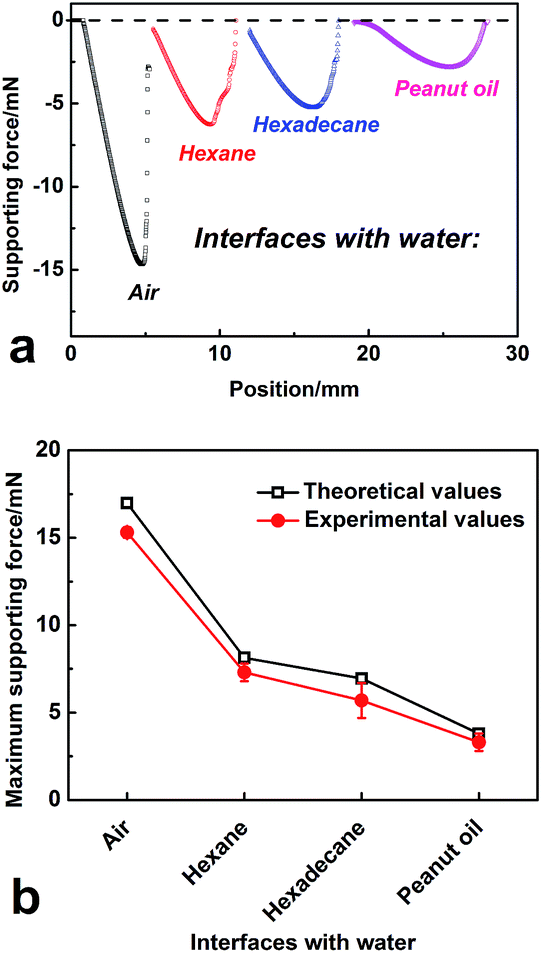 | ||
| Fig. 7 (a) Plots of supporting force versus immersed position for superhydrophobic meshes floating at air/water and various oil/water interfaces. For better observation, these plots are horizontally shifted. A negative value of a force indicates that it is in an upward direction. (b) The experimental and calculated comparisons of the maximum supporting force for superhydrophobic mesh at various interfaces with water. | ||
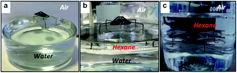
In order to apply our findings, a micro-robot model supported by floating FAS-meshes was manufactured. Fig. 8 shows the as-prepared micro-robot model. Four “legs” with circular meshes of R = 8 ± 0.2 mm were used to control the floating of this model. Obviously, the model can easily float in air (see Fig. 8a). We poured hexane into water to observe if the micro-robot still floated on the water (see Fig. 8b and c). After more hexane was poured into the vessel, the model always floated at the hexane/water interface even if it was completely immersed in hexane (see Video S1†). The maximum floating force of the micro-robot model at the two interfaces was measured as 43.3 ± 0.8 mN and 18.6 ± 0.7 mN, respectively. Therefore, our model (its weight was ∼857 mg, approximately equivalent to 8.4 mN) can remain standing at the two interfaces, but not sink.
 | ||
| Fig. 8 Micro-robot model in various floating states: (a) floating in air, (b) partially floating at the hexane/water interface, (c) complete immersion into hexane and then floating at the hexane/water interface. | ||
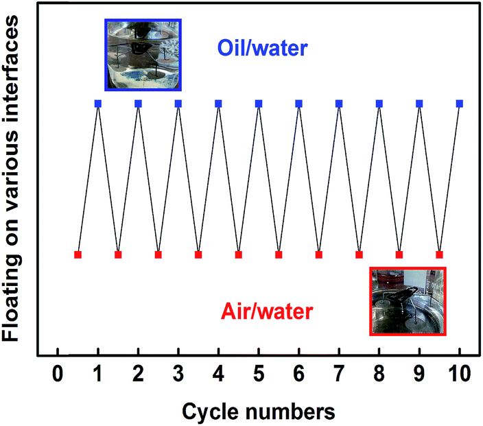
If we consider oil contamination dispersedly floating on wastewater, the micro-robot has the chance to alternately pass air/water and oil/water interfaces during the inspection. We recorded the floating states of the model after it was placed at the air/water interface and then at the hexane/water interface for ten cycles (see Fig. 9). Clearly, the model always floated at air/water and hexane/water interfaces, regardless of the number of cycles. Oils that adhere to the mesh develop local oil/water interfaces when the mesh is repeatedly placed on water, but these cannot affect the floating of the micro-robot. The large supporting forces of the mesh supports at the oil/water interface prevent the micro-robot from falling into the water, so the model is able to float on a discontinuous oil-polluted water surface.
 | ||
| Fig. 9 Floating states of the model micro-robot when it is repeatedly placed at air/water and hexane/water interfaces for ten cycles. The solid symbol ■ indicates that the model is floating. | ||
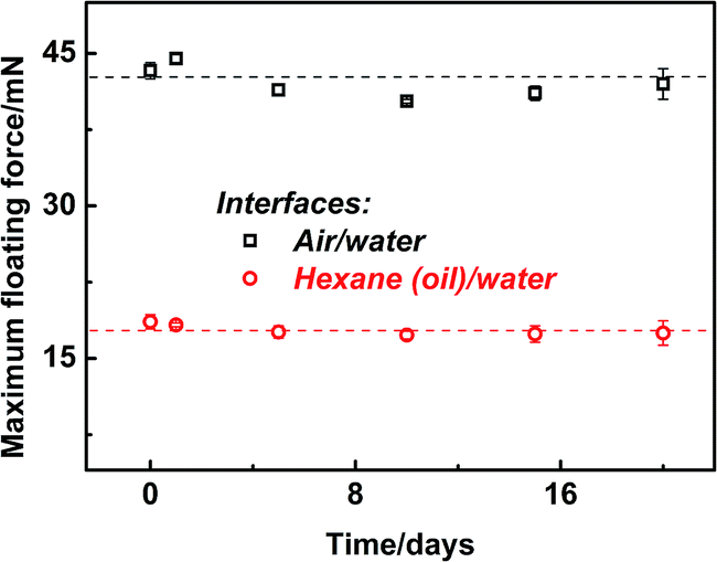
The floating stability of the model is very important for our designs. Especially, the stability of FAS-mesh for the micro-robot at oil/water interfaces is problematic due to ultra-low interface tension and was checked in our experiments. We put the model on water and then poured hexane into the vessel until it was completely immersed. The vessel was dramatically shaken by hand and the oil/water interface was strongly disturbed, but the model micro-robot remained firmly standing at the interface. After the shaking of the vessel stopped and it was placed on a platform, the continuous waves of the interface could not sink the model (see Video S2†). This suggests that the model has high stability when it freely floats at an oil/water interface. Besides, the long-term stability of the model was also tested. Fig. 10 shows the effect of floating time on the maximum loading capacity of the model. After floating for 20 days, the model retained a loading capacity of around 42 ± 1.5 mN and 17.5 ± 1.3 mN at air/water and hexane/water interfaces, respectively, which suggests the long-term stability of the supporting forces of the legs. Here, the stable and durable floatability of the micro-robot model supports the subsequent control of its movement at air/water and oil/water interfaces by an external magnetic field.
 | ||
| Fig. 10 Plots of measured supporting force of FAS-mesh versus floating time at air/water and hexane/water interfaces. | ||
To simulate the environment of pipes, the model was placed in a closed system. It first floated at the air/water interface in a vessel covered by a Petri dish. A permanent magnet was introduced from above at a distance of about 5 cm to prevent the model from being directly touched. The model responded to the magnetic field and moved directly below the magnet, as shown in Fig. 11a–d. When the magnet was freely moved, the model followed the same movements (see Video S3†). Once the magnet was taken away, the model would stand on the water surface. On the other hand, the closed system was placed on a magnetic stirrer. Fig. 11e–h shows the responses of the robot model after a magnetic stirrer was in contact with it. When we turned on the power, the floating robot would rotate just like a stirring bar. Upon an increase in the rotation speed, the robot responded quickly to rotate (see Video S4†).
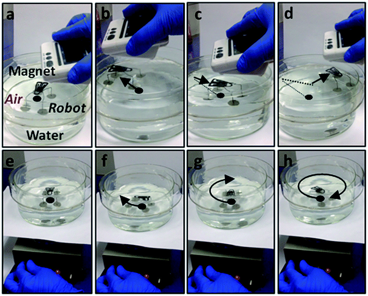 | ||
| Fig. 11 Directional movements of the micro-robot model at the air/water interface in a closed system, guided by a magnetic field. (a–d) The robot follows the same movements when the magnet moves. (e–h) The floating robot rotates like the stirring bar once it is placed on a running magnetic stirrer. The black dot indicates the initial position of the robot and the arrow represents its direction of motion. | ||
In the same way, we floated the robot at an oil/water interface and then attracted it by a permanent magnet. Fig. 12 shows vertical and lateral views of the motion of the model at the hexane/water interface under the guidance of the magnet. By applying the magnetic field, the robot can easily move at such an oil/water interface, which indicates good remote-control operation (see Video S5†). Moreover, if the magnet was placed under the bottom of the vessel, the robot was still guided to move by it. This situation suggests that the uses of a magnetic field are flexible for driving the movements of the robot from more directions. Furthermore, the robot could responsively rotate at the hexane/water interface when it was put on a magnetic stirrer (see Video S6†). We extended these experiments into an open system. The observations were encouraging; that is, all results were the same as those in the closed system (see Video S7†). Especially when the rotation speed of the magnetic stirrer reached 100 rpm, more oil (hexane) was poured into the vessel, which caused strong disturbance of the oil/water interface. Accompanying the waves of the interface, the micro-robot stably rotated under magnetic attraction (see Video S8†). It is stressed that our micro-robot model that could float, move and rotate at air/water and oil/water interfaces is really an advanced version and possesses a clear advantage over static floating models.15,16
 | ||
| Fig. 12 Micro-robot model directionally moves along the oil/water interface in a closed system. (a–d) A series of movements of a magnet over a closed system lead to it guiding the micro-robot. | ||
As far as we know, the power supply is a troubling problem that restricts the applications and working capacity of micro-robots. By applying a magnetic field, a responsive robot can dramatically reduce its possible battery consumption to move and then retain enough energy to enable it to inspect a large-sized closed system or long-distance pipeline. Therefore, remote magnetic control of floating micro-robots is believed to be a good solution for promoting robot technology in pipeline detection.
Conclusion
To improve the detecting ability for small-sized or bent pipes, an advanced micro-robot was designed to freely move at air/water and oil/water interfaces using an external magnetic field. To realize the design, superhydrophobic and magnetically responsive supports in air and under oil were theoretically needed. Therefore, a superhydrophobic ferrous mesh was fabricated by a simple fluorination process. Micron-sized structures of the mesh provide “overhang” structures to develop composite surfaces that suspend a droplet to produce high water repellency in air and under oil. Due to its superhydrophobicity, the mesh possesses a large supporting force and high floating stability at air/water and oil/water interfaces. Guided by a magnetic field, the model can directionally move and rotate at the two interfaces without an extra battery supply. The design of a floating micro-robot on water and the investigation of its movements at interfaces could greatly support future work to develop more functions for the micro-robot, for example, cleaning, repair and maintenance of wastewater pipelines. Therefore, we believe that our findings can be well applied to aquatic micro-devices to enable sewage inspection.Acknowledgements
This work was supported by the National Natural Science Foundation of China (51103033) and China Scholarship Council (CSC).Notes and references
- L. P. Gossen and L. M. Velichkina, Pet. Chem., 2006, 46, 67 CrossRef.
- H. Wang, Y. Gong and Y. Wang, RSC Adv., 2014, 4, 45753 RSC.
- I. Angelidaki and B. K. Ahring, Biodegradation, 1997, 8, 221 CrossRef CAS.
- M. Yang and T. Su, Expert. Syst. Appl., 2008, 35, 1327 CrossRef PubMed.
- J. Qian, Y. Zhang, L. Sun, X. Qin and Y. Shen, J. Shanghai Univ., 2000, 4, 235 CrossRef.
- M. Tavakoli, L. Marques and A. T. de Almeida, Ind. Robot, 2010, 37, 309 CrossRef.
- M. Mailah, E. Pitowarno and H. Jamaluddin, Int. J. Adv. Robotic Syst., 2005, 2, 125 Search PubMed.
- (a) Z. Xue, Z. Sun, Y. Cao, Y. Chen, L. Tao, K. Li, L. Feng, Q. Fu and Y. Wei, RSC Adv., 2013, 3, 23432 RSC; (b) Y. Chen, Z. Xue, N. Liu, F. Lu, Y. Cao, Z. Sun and L. Feng, RSC Adv., 2014, 4, 11447 CAS.
- P. Calcagnile, D. Fragouli, I. S. Bayer, G. C. Anyfantis, L. Martiradonna, P. D. Cozzoli, R. Cingolani and A. Athanassiou, ACS Nano, 2012, 6, 5413 CrossRef CAS PubMed.
- M. Cheng, G. Ju, C. Jiang, Y. Zhang and F. Shi, J. Mater. Chem. A, 2013, 1, 13411 CAS.
- X. Zhang, L. Wang and E. Levänen, RSC Adv., 2013, 3, 12003 RSC.
- B. N. Sahooa and B. Kandasubramanian, RSC Adv., 2014, 4, 22053 RSC.
- J. Zhang, H. Feng, W. Zao, M. Ling and Y. Zhao, RSC Adv., 2014, 4, 4844 Search PubMed.
- K. Liu and L. Jiang, Nanoscale, 2011, 3, 825 RSC.
- I. A. Larmour, S. E. J. Bell and G. C. Saunders, Angew. Chem., Int. Ed., 2007, 46, 1710 CrossRef CAS PubMed.
- (a) Q. Pan and M. Wang, ACS Appl. Mater. Interfaces, 2009, 1, 420 CrossRef CAS PubMed; (b) Q. Pan, J. Liu and Q. Zhu, ACS Appl. Mater. Interfaces, 2010, 2, 2026 CrossRef CAS.
- (a) F. Shi, Z. Q. Wang and X. Zhang, Adv. Mater., 2005, 17, 1005 CrossRef CAS PubMed; (b) M. Xiao, M. Cheng, Y. Zhang and F. Shi, Small, 2013, 9, 2509 CrossRef CAS PubMed.
- X. Feng, X. Gao, Z. Wu, L. Jiang and Q. Zheng, Langmuir, 2007, 23, 4892 CrossRef CAS PubMed.
- F. Yang and Z. Guo, RSC Adv., 2015, 5, 13635 RSC.
- X. Liu, J. Gao, Z. Xue, L. Chen, L. Lin, L. Jiang and S. Wang, ACS Nano, 2012, 6, 5614 CrossRef CAS PubMed.
- C. Huh and S. G. Mason, J. Colloid Interface Sci., 1974, 47, 271 CrossRef.
- A. V. Rapacchietta and A. W. Neumann, J. Colloid Interface Sci., 1977, 59, 555 CrossRef.
- (a) C. W. Extrand and S. I. Moon, Langmuir, 2009, 25, 992 CrossRef CAS PubMed; (b) C. W. Extrand and S. I. Moon, Langmuir, 2009, 25, 2865 CrossRef CAS PubMed.
- H. Wang, J. Yu, Y. Wu, W. Shao and X. Xu, J. Mater. Chem. A, 2014, 2, 5010 CAS.
- A. B. D. Cassie and S. Baxter, Trans. Faraday Soc., 1944, 40, 546 RSC.
- G. Zhang, X. Zhang, Y. Huang and Z. Su, ACS Appl. Mater. Interfaces, 2013, 5, 6400 CAS.
- (a) M. Jin, S. Li, J. Wang, Z. Xue, M. Liao and S. Wang, Chem. Commun., 2012, 48, 11745 RSC; (b) M. Jin, J. Wang, X. Yao, M. Liao, Y. Zhao and L. Jiang, Adv. Mater., 2011, 23, 2861 CrossRef CAS PubMed; (c) J. Gao, X. Yao, Y. Zhao and L. Jiang, Small, 2013, 9, 2515 CrossRef CAS PubMed.
- (a) C. Ding, Y. Zhu, M. Liu, L. Feng, M. Wan and L. Jiang, Soft Matter, 2012, 8, 9064 RSC; (b) L. Heng, J. Su, J. Zhai, Q. Yang and L. Jiang, Langmuir, 2011, 27, 12466 CrossRef CAS PubMed.
- D. Zang, C. Wu, R. Zhu, W. Zhang, X. Yu and Y. Zhang, Chem. Commun., 2013, 49, 8410 RSC.
- V. Hejazi and M. Nosonovsky, Langmuir, 2012, 28, 2173 CrossRef CAS PubMed.
- D. Deng, D. P. Prendergast, J. MacFarlane, R. Bagatin, F. Stellacci and P. M. Gschwend, ACS Appl. Mater. Interfaces, 2013, 5, 774 CAS.
- V. Hejazi, A. E. Nyong, P. K. Rohatgi and M. Nosonovsky, Adv. Mater., 2012, 24, 5963 CrossRef CAS PubMed.
- W. Choi, A. Tuteja, S. Chhatre, J. M. Mabry, R. E. Cohen and G. H. McKinley, Adv. Mater., 2009, 21, 2190 CrossRef CAS PubMed.
- A. Tuteja, W. Choi, M. L. Ma, J. M. Mabry, S. A. Mazzella, G. C. Rutledge, G. H. McKinley and R. E. Cohen, Science, 2007, 318, 1618 CrossRef CAS PubMed.
- L. Zhang, Y. Zhong, D. Cha and P. Wang, Sci. Rep., 2013, 3, 2326 Search PubMed.
- X. Zhu, Z. Zhang, J. Yang, X. Xu, X. Men and X. Zhou, J. Colloid Interface Sci., 2012, 380, 182 CrossRef CAS PubMed.
- X. Zhou, Z. Zhang, X. Xu, F. Guo, X. Zhu, X. Men and B. Ge, ACS Appl. Mater. Interfaces, 2013, 5, 7208 CAS.
- X. Deng, L. Mammen, H.-J. Butt and D. Vollmer, Science, 2012, 335, 67 CrossRef CAS PubMed.
- Z. Cheng, R. Hou, Y. Du, H. Lai, K. Fu, N. Zhang and K. Sun, ACS Appl. Mater. Interfaces, 2013, 5, 8753 CAS.
Footnote |
| † Electronic supplementary information (ESI) available: Graphs show additional information concerning XPS information, optical images of rolling-off angles in air and under oil, and videos show floatability of FAS-mesh at air/water and oil/water interfaces, and its floating stability at oil/water interface. See DOI: 10.1039/c5ra05921f |
| This journal is © The Royal Society of Chemistry 2015 |