A novel EVA composite with simultaneous flame retardation and ceramifiable capacity

Hong-Wei Di, Cong Deng*, Rui-Min Li, Liang-Ping Dong and Yu-Zhong Wang*
Center for Degradable and Flame-Retardant Polymeric Materials, College of Chemistry, State Key Laboratory of Polymer Materials Engineering, National Engineering Laboratory of Eco-Friendly Polymeric Materials (Sichuan), Analytical and Testing Center, Sichuan University, Chengdu 610064, China. E-mail: dengcong@scu.edu.cn; yzwang@scu.edu.cn; Fax: +86-28-85410259; Tel: +86-28-85410259

Received 1st April 2015 , Accepted 1st June 2015

First published on 2nd June 2015


Abstract

Ethylene-vinyl acetate (EVA) filled with glass dust (GD), glass fiber (GF), OMMT, and melamine cyanurate (MCA) was developed as a ceramifiable flame-retardant polymer composite for cables and insulated wires. The ceramics formed at different high temperatures based on the ceramifiable flame-retardant polymer composites were investigated by mechanical testing, scanning electron microscopy (SEM), and energy dispersive X-ray (EDX) spectroscopy; the flame retardation of the ceramifiable flame-retardant EVA composites was studied with the aid of vertical burning testing (UL-94), limiting oxygen index (LOI), and cone calorimeter (CC) tests. The results showed that the ceramics were prepared successfully at different high temperatures based on the ceramifiable flame-retardant polymer composites. For the EVA/GD/GF/OMMT/MCA system with a weight ratio of 35/26/9/5/25, the ceramic formed at 800 °C had a flexural strength of 13.82 MPa, and both a UL-94 V-0 rating and a LOI of 28.2% were achieved. Moreover, CC results confirmed that the heat release rate (HRR), total release rate (THR), smoke production rate (SPR), and mass loss rate (MLR) of the composite were reduced significantly compared with the corresponding value of neat EVA or the ceramifiable EVA composite without MCA. The dilatometric experiment analysis, SEM, and viscosity analysis demonstrated that a eutectic mixture resulting from GD and GF led to the formation of ceramics at high temperature. Thermal gravimetric analysis (TG), etc. illustrated that both the release of a large amount of non-flammable gas and the presence of OMMT led to the much better flame retardancy of EVA/GD/GF/OMMT/MCA than that of neat EVA or the ceramifiable EVA composites without MCA.

1. Introduction

Ethylene-vinyl acetate copolymer (EVA) is widely used in many fields, especially in the cable industry as an insulating material owing to its excellent physical and mechanical properties.1–4 However, EVA copolymers are particularly flammable, and emit a large amount of smoke during burning, which restricts their practical applications. To flame retard EVA, halogenated additives or non-halogen additives are incorporated into EVA.5–8 Even so, some requirements cannot be met in fire accidents, for example, the sandwich layer of a cable cannot be protected by the flame-retardant EVA composites in the nuclear reactor, which might lead to the interruption of power, subsequently resulting in a terrible nuclear accident. However, the flame-retardant materials with high temperature resistance can be used to solve the problem. Ceramic is a kind of high temperature resistance material, which has some special properties, such as fire resistance, good mechanical properties, water resistance, and so on,9–12 so the fabrication of a ceramifiable flame-retardant EVA composite should be an ideal method to ensure safety in fire accidents such as that which occur in the nuclear power industry.

Firstly, to flame retard EVA, both the halogenated and non-halogenated additives were used to achieve the aim. For the halogenated flame retardants, their use is being reduced due to their environmental pollution, especially in Europe. More attentions have been shifted to the non-halogen flame retardants in current industrial and scientific fields, including magnesium hydroxide, aluminum hydroxide, aluminum hypophosphite, intumescent flame retardant, and so on.13–16 For these flame retardants, the condensed phase, gas phase, or both of them can bring good flame retardation for EVA during the combustion process. For the ceramifiable flame-retarded polymer composite, its ceramic formed at high temperature should meet the requirements of mechanical properties in practical application. However, the char residue resulting from flame retardant may greatly weaken the strength of the formed ceramic, so the char residue should be as little as possible to ensure the good mechanical properties of ceramic formed at high temperature for the ceramifiable flame-retarded polymer composite. Obviously, the non-halogenated flame retardant, for which the gas phase action is dominant in flame retarding polymer, should be an optimal choice for fabricating a ceramifiable flame-retarded polymer composite due to its low char residue. Generally, gas phase flame-retardant mechanism includes chemical and physical methods. Melamine cyanurate (MCA), as an environmentally friendly flame retardant, was developed in early 1980s. It is a gas-phase flame retardant, which acts through the dilution of combustible gases in flame retarding polymers, and widely used in flame retarding PP17 and epoxy resin18 based on its gas phase flame-retardant mechanism, so it might be an efficient flame retardant in preparing the ceramifiable flame-retarded EVA composite.

To prepare the ceramic based on EVA composite, silicate minerals and inorganic ingredients can be incorporated into the polymer composite, which was confirmed by Pinacci et al.19 and Alexander et al.20 Pinacci et al.19 invented a cable comprising an organic polymer, a glass frit, a silicate mineral with a softening point or a melting temperature of not less than 1000 °C, and they found that inorganic materials such as silicate could lead to the formation of a compact ceramic for the polymer composite. Alexander et al.20 created a ceramifiable composition to form a fire resistant ceramic, in which there are a mineral silicate, an inorganic phosphate that can form a liquid phase at a temperature of no more than 800 °C, an organic polymer, etc., and they found that the ceramic formed had the fire-resistance temperature above 1000 °C.

In this work, the ceramifiable flame-retarded EVA composites are prepared on the basis of EVA, MCA, silicate minerals, and inorganic ingredients. The flame retardancy of EVA composite was investigated with the aid of CC, LOI, and UL-94 tests, and the fire-retardant mechanism of ceramifiable EVA composite was also investigated through TG, SEM, etc. Meanwhile, the ceramics formed under high temperature based on the ceramifiable flame-retarded EVA composites were also analyzed using different measurements.

2. Experiment section

2.1. Materials

EVA (Elvax 260, 28% vinyl acetate) was supplied by DuPont Company (USA). Glass dust (GD) with low softening point was purchased from Dong Gu New Materials Co. Ltd. (Nanhai, China), which is composed of P2O5: 45.13%, Al2O3: 23.82%, K2O: 14.05%, Na2O: 10.03%, SiO2: 5.47%, CaO: 0.91%, TiO2: 0.41%, SO3: 0.08%, Fe2O3: 0.03%, ZnO: 0.01%, volatile compounds: 0.06%, and minor oxides. E-glass fiber (GF) was provided by Radison Composites Co. Ltd. (Nanjing, China). OMMT (I.44P) was purchased from Nano Co. Ltd. (USA), and it is a kind of organically-modified clay in which the cation absorbed in the interlay is mainly sodium ion (Na+). Dicumyl peroxide (DCP) was from Kelong Chemical Reagent Co. Ltd. (Chengdu, China). Melamine cyanurate (MCA) was supplied from Sichuan Fine Chemical Research and Design Institute (Chengdu, China).

2.2. Sample preparation

2.2.1 Samples for combustion test. EVA, MCA, silicate minerals, and inorganic ingredients were dried in a vacuum oven at 50 °C for 12 h. Then EVA composites filled with different ratios of additives were prepared via a twin-screw extruder (CTE 20, Kebeilong Keya Nanjing Machinery Co., Ltd, Nanjing, China) with the rotation speed of 150 rpm at the following temperature protocol from the feed zone to the die: 175, 180, 190, 185, 180 and 170 °C. Finally the extruded pellets were hot-pressed into different samples by plate vulcanizer (Qingdao Yadong Rubber machinery Co. Ltd. China).
2.2.2 Ceramic for mechanical test. Pyrolysis of sheet samples (30 × 4 × 3 mm) was performed using a muffle furnace KSL-1200X (Hefei Kejing Material Technology Co. Ltd., China). Samples were heated from room temperature to 600, 700, 800, 900, and 1000 °C respectively at a heating rate of 10 °C min−1, then the ceramic samples were prepared successfully.

2.3. Measurements

The flexural strength of the ceramic was determined by the 3-point bend method using an Universal Testing Machine (CMT2000, SANS, Inc. Shenzhen, China) in accordance with the procedures in GB 6569-2006. The load was applied at a rate of 0.5 mm min−1. All data are the average of five independent flexural strengths.

Tensile test was completed on a universal experimental machine (CMT2000, SANS, Inc. Shenzhen, China) in accordance with the procedures in GB/T 1040.3-2006 at an extension speed of 20 mm min−1 at room temperature. The specimens are the dumbbell with the size of 50 mm × 4 mm (the breadth of cabined section) × 1 mm, and the length of cabined section is 20 mm. All data are the average of five independent tensile strengths.

The morphology and elemental dispersion of the ceramics prepared were analyzed by SEM–EDX using a JEOL JSM 5900LV scanning electron microscope (JEOL, Japan) and a EDX system (OXFORD INCA250, USA). The accelerated voltage is 20 kV. All specimens were coated with a conductive layer before being examined.

The dilatometric experiment was performed in a horizontal dual-rod dilatometer (Model DIL 402, NETZSCH, Germany) at heating rate of 10 °C min−1. The experiments for the as-prepared samples were carried out to estimate the Tg. The dilatometric softening point Tf can be determined from the maximum of the dilatometric curve.

The viscosity of ceramic residue prepared was measured with a rotating crucible viscometer (Model Rheotronic II, THE TA, USA). About 100 g of ceramic residue was added into a Pt crucible. The viscometer spindle was placed in the center of the crucible, and the viscometer was calibrated for 5 times with a standard quartz glass before testing. The standard measurement error is less than 0.05 log unit.

The insulating property of the ceramic was measured using Megger (ZC36, Shanghai Jian Yi Precision Instrument Co., Ltd, China) with a sheet dimension of Φ 50 mm × 2.8 mm.

The LOI value was measured using an HC-2C oxygen index instrument (Jiangning, China) according to ASTM D2863-97 with a sheet dimension of 130 mm × 6.5 mm × 3.2 mm.

The UL-94 vertical burning level was tested on a CZF-2 instrument (Jiangning, China) according to ASTM D3801, the dimensions of samples are 130 mm × 13 mm × 3.2 mm.

The flammability of the samples were measured by a cone calorimeter device (Fire Testing Technology, UK). The samples with dimension of 100 mm × 100 mm × 3 mm were exposed to a radiant cone at a heat flux of 50 kW m−2.

XRD test was performed using an instrument with an Cu-Kα radiation (DX-1000 CSC, Dandong Fangyuan Instrument Co. Ltd, China). The 1 mm thick films were tested from 2 to 50° with the step length of 0.06° at 40 kV.

TGA was performed on a thermo gravimetric analyzer instrument (209 F1, NETZSCH, Germany) at a heating rate of 10 °C min−1 under N2 or air atmosphere at a flow rate of 50 mL min−1 in the temperature range from 40 to 800 °C. The TG-IR instrument consists of a thermo gravimeter (TGA/DSC1/1100LF, METTLER TOLEDO, Switzerland), a Fourier transform infrared spectrometer (6700, Nicolet, America), and a transfer tube with an inner diameter of 1 mm. The investigation was carried out from 30 to 700 °C at a linear heating rate of 10 °C min−1 under the nitrogen flow rate of 3 × 10⁻⁵ m3 min−1.

3. Results and discussion

3.1. Preparation of EVA composites-based ceramic

Table 1 shows the flexural strength of the ceramic formed at different temperatures based on the ceramifiable EVA composites with various ratios of GD/GF. Here, the ceramifiable filler composed of GD and GF is named as CF, and the ratio of EVA/CF/OMMT is 50/45/5. In the case of 0 or 3 wt% OMMT in EVA, the irregular shape of EVA composites-based ceramic was observed due to the high flow capacity of the melted EVA/CF/OMMT composite, so the corresponding mechanical properties of the ceramic resulting from the EVA/CF containing 0 or 3 wt% OMMT were not measured in our experiment. For EVA/CF/OMMT composites with 5 wt% OMMT, the flexural strength of ceramic increased with increasing the ratio of GD/GF in CF until the ratio reached to 3/1, and then it declined with further increasing the ratio of GD/GF, the maximum is 15.45 MPa at 700 °C. At higher pyrolyzing temperature, the change for the flexural strength of ceramic has a similar tendency. However, the ratio of GD/GF reduced while reaching the maximum flexural strength for the ceramic, and the ratio values are 2/1, 4/3, and 1/1, respectively, corresponding to the maximum 23.62 MPa at 800 °C, 28.89 MPa at 900 °C, and 39.00 MPa at 1000 °C. Obviously, the loading of glass fillers has an significant effect on the flexural strength of the EVA composites-based ceramic. In Table 1, it can be found that the ratio of 3/1 (GD/GF) is a suitable value to fabricate the EVA composite-based ceramic if we consider forming the ceramic at low temperature, so it was chosen to prepare the flame-retarded EVA composites.
Table 1 Flexural strength of the ceramics formed at different temperatures for EVA/CF/OMMT systems
Composition(phr) Flexural strength (MPa)
700 °C 800 °C 900 °C 1000 °C
EVA/CF(GD[thin space (1/6-em)]:[thin space (1/6-em)]GF = 1[thin space (1/6-em)]:[thin space (1/6-em)]1)/OMMT 4.67[thin space (1/6-em)]±[thin space (1/6-em)]0.42 10.61 ± 1.01 27.14 ± 1.25 39.00 ± 1.90
EVA/CF(GD[thin space (1/6-em)]:[thin space (1/6-em)]GF = 4[thin space (1/6-em)]:[thin space (1/6-em)]3)/OMMT 6.28[thin space (1/6-em)]±[thin space (1/6-em)]0.33 17.13 ± 1.68 28.89 ± 2.19 36.19 ± 1.79
EVA/CF(GD[thin space (1/6-em)]:[thin space (1/6-em)]GF = 2[thin space (1/6-em)]:[thin space (1/6-em)]1)/OMMT 9.02[thin space (1/6-em)]±[thin space (1/6-em)]0.64 23.62 ± 1.37 28.12 ± 1.12 29.04 ± 1.99
EVA/CF(GD[thin space (1/6-em)]:[thin space (1/6-em)]GF = 5[thin space (1/6-em)]:[thin space (1/6-em)]2)/OMMT 10.65[thin space (1/6-em)]±[thin space (1/6-em)]1.05 19.05 ± 1.71 24.01 ± 0.69 20.24 ± 1.54
EVA/CF(GD[thin space (1/6-em)]:[thin space (1/6-em)]GF = 3[thin space (1/6-em)]:[thin space (1/6-em)]1)/OMMT 15.45[thin space (1/6-em)]±[thin space (1/6-em)]1.33 18.15 ± 1.52 21.53 ± 1.81 17.56 ± 1.42
EVA/CF(GD[thin space (1/6-em)]:[thin space (1/6-em)]GF = 4[thin space (1/6-em)]:[thin space (1/6-em)]1)/OMMT 10.87[thin space (1/6-em)]±[thin space (1/6-em)]1.05


3.2. SEM measurement of EVA composites-based ceramic

Fig. 1 shows SEM micrographs of the ceramics prepared at 700 °C. Fig. 1a shows that GD was melted at the edges, and might be bridged with GF. In this case, the temperature was not high enough to make GF melted, so the adhesion of GF to the solidified phase of GD is rather poor (Fig. 1a). With increasing the GD, the interfaces between GD and GF became blurred, especially in Fig. 1c, indicating that the bonding between GF and GD was improved with increasing GD.
image file: c5ra05781g-f1.tif
Fig. 1 SEM micrographs of EVA composites-based ceramics obtained at 700 °C. GD/GF = 1/1 (a1, a2, a3); GD/GF = 2/1 (b1, b2, b3); GD/GF = 3/1 (c1, c2, c3).

3.3. Fabrication of ceramifiable flame-retarded EVA composites

To achieve the flame retardancy of EVA/CF/OMMT system, MCA was incorporated into the system. The flame retardancy of the EVA/CF/OMMT/MCA composites was evaluated by LOI and UL-94 tests, and the results are shown in Table 2. At 25 wt% MCA, the EVA composite passed the V-0 rating, meanwhile, the LOI value of the composite reached 28.2%. Obviously, MCA is an effective flame retardant for EVA/CF/OMMT. Generally, OMMT is a typical synergistic flame retardant, so the effect of its concentration on the flame retardancy was also investigated in this work. Based on the flame retardation of EVA/CF/OMMT/MCA with 30 wt% MCA and OMMT, the flame retardation of EVA composite has apparent fluctuation with changing the OMMT from 0 or 7 wt%. The EVA composite was no rating in UL-94 test at 0 or 3 wt% OMMT, and it was the V-2 rating at 7 wt% OMMT. Obviously, OMMT played a good synergistic role in flame retarding EVA through MCA, which is consistent with the conclusion reported by Deng21 and Li et al.22 Moreover, 5 wt% OMMT should be near the ideal concentration for the flame retardation of EVA/CF/OMMT/MCA composite.
Table 2 LOI and UL-94 data of EVA composites
Sample EVA CF(GD[thin space (1/6-em)]:[thin space (1/6-em)]GF = 3[thin space (1/6-em)]:[thin space (1/6-em)]1) OMMT MCA UL-94 LOI
1 50 50 0 0 N.R./dripping
2 50 47 3 0 N.R./dripping
3 50 45 5 0 N.R./no dripping
4 40 45 5 10 N.R.
5 35 45 5 15 N.R.
6 35 40 5 20 N.R.
7 35 35 5 25 V-0 28.2
8 35 35 0 30 N.R. 26.5
9 35 35 3 27 N.R. 27.5
10 35 35 7 23 V-2 27.8


3.4. Effect of DCP on the mechanical properties of ceramifiable flame-retarded EVA composites

To improve the mechanical properties of EVA/CF/OMMT/MCA composite, DCP was added into the composite. The tensile strengths and elongations at break of flame-retardant EVA composites with different DCP concentrations are shown in Table 3. The tensile strength of flame-retardant EVA composite increases with increasing the DCP to 0.04 wt%, and then the tensile strength is almost kept at about 11.5 MPa with increasing the DCP to 0.06 wt%. However, the elongation at break of flame-retardant EVA composite has the different change tendency. Firstly, it increases with increasing the DCP to 0.05 wt%, then it decreases with the further increase of DCP. Obviously, 0.05 wt% DCP should be near the suitable content to improve the mechanical properties of EVA/CF/OMMT/MCA composite.
Table 3 Mechanical properties of EVA composites
Composition(phr) Tensile strength (MPa) Elongation at break (%)
EVA35/CF35/OMMT5/MCA25 9.43[thin space (1/6-em)]±[thin space (1/6-em)]0.34 39.23[thin space (1/6-em)]±[thin space (1/6-em)]3.45
EVA35/CF35/OMMT5/MCA25/DCP0.02 9.97[thin space (1/6-em)]±[thin space (1/6-em)]0.21 80.64[thin space (1/6-em)]±[thin space (1/6-em)]7.49
EVA35/CF35/OMMT5/MCA25/DCP0.04 11.49[thin space (1/6-em)]±[thin space (1/6-em)]0.28 181.27[thin space (1/6-em)]±[thin space (1/6-em)]19.53
EVA35/CF35/OMMT5/MCA25/DCP0.05 11.54[thin space (1/6-em)]±[thin space (1/6-em)]0.38 244.37[thin space (1/6-em)]±[thin space (1/6-em)]17.48
EVA35/CF35/OMMT5/MCA25/DCP0.06 11.66[thin space (1/6-em)]±[thin space (1/6-em)]0.52 193.79[thin space (1/6-em)]±[thin space (1/6-em)]14.24


3.5. Combustion performance of the ceramifiable flame-retarded EVA composites

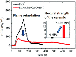
Cone calorimeter is an effective method to study the flammability of polymer composites.23–25 The heat release rate (HRR), total release rate (THR), smoke production rate (SPR), and mass loss rate (MLR) curves of neat EVA and EVA composites are shown in Fig. 2, and the corresponding data are summarized in Table 4. Here, it should be noted that all the systems contain 0.05 wt% DCP. As shown in Fig. 2a, pure EVA burnt out within 360 s after being ignited. A very sharp peak of HRR (PHRR) appeared quickly, and the value is about 875.8 kW m−2. However, the flame-retardant EVA composites showed a dramatic decline for the PHRR. The 225.4 kW m−2 for EVA/CF/MCA/OMMT is slightly lower than 255.4 kW m−2 for EVA/CF/MCA, much lower than 359.8 kW m−2 for EVA/CF. Moreover, the HRR curve of flame-retarded EVA composites exhibits two peaks. The first peak is due to the combustion and the formation of an protective shield; the second one is explained by the destruction of the intumescent structure and the formation of a carbonaceous–inorganic residue.
image file: c5ra05781g-f2.tif
Fig. 2 HRR (a), THR (b), SPR (c), and ML (d) curves of neat EVA and EVA composites in CC test.
Table 4 CC data of EVA and EVA composites
Sample PHRR (kW m−2) THR (MJ m−2) Peak SPR (1 × 10⁻² m2 s−1) Residue (wt%)
EVA100/DCP0.05 875.8 85.7 8.9 6.8
EVA35/CF35/DCP0.05 359.8 75.6 5.6 52.5
EVA35/CF35/MCA30/DCP0.05 255.4 69.1 1.2 43.2
EVA35/CF35/MCA25/OMMT5/DCP0.05 225.4 68.0 1.2 46.4


The total heat release (THR) is used to evaluate the fire safety of the materials in a real fire. From Fig. 2b, an obvious THR decrease can be observed for EVA composites compared with neat EVA. At the end of the test, neat EVA released a total heat of 85.7 MJ m−2, whereas EVA/CF, EVA/CF/MCA, and EVA/CF/MCA/OMMT released total heat of 75.6, 69.1, and 68.0 MJ m−2, respectively. The THR values also demonstrate that EVA/CF/MCA/OMMT system has better fire safety than the other systems presented in Table 4.

The SPR and MLR curves of EVA and EVA composites are presented in Fig. 2c and d. It is noticeable that the peak of SPR (PSPR) for EVA/CF, EVA/CF/MCA, and EVA/CF/MCA/OMMT composites are dramatically reduced compared with neat EVA. The PSPR peak of neat EVA is 8.9 × 10⁻² m2 s−1. Compared with neat EVA, the PSPR values of both EVA/CF/MCA/OMMT and EVA/CF/MCA composites were remarkably decreased to 1.2 × 10⁻² m2 s−1. These results indicate that the smoke suppression effect of both EVA/CF/MCA/OMMT and EVA/CF/MCA composites are significantly improved compared with EVA/CF composite. For EVA/CF/MCA composite, the average MLR decreased to 0.036 g s−1 from 0.065 g s−1 for neat EVA, and it further reduced to 0.032 g s−1 for EVA/CF/MCA/OMMT composite. Obviously, the CF, MCA, and OMMT contribute to the flame retardation of EVA.

The digital photographs of the residues for the four systems after CC test are shown in Fig. 3. As can be seen, there is no residue left for EVA after CC test. While a char layer was formed for EVA/CF, EVA/CF/MCA or EVA/CF/MCA/OMMT composite. The residue of EVA/CF/MCA/OMMT composite is obviously more compact than that of EVA/CF or EVA/CF/MCA composite. No big holes or cracks can be observed in the residue of EVA/CF/MCA/OMMT composite. The compact char layer contributes to the flame retardation of EVA composite, which should be an important reason for the better flame retardation of EVA/CF/MCA/OMMT composite than that of EVA/CF or EVA/CF/MCA composite.


image file: c5ra05781g-f3.tif
Fig. 3 Digital photographs of the residue char after CC test. (a), EVA; (b), EVA/CF; (c), EVA/CF/MCA; (d) EVA/CF/MCA/OMMT.

3.6. Mechanical properties and morphologies of the ceramics formed at various temperatures for EVA/CF/MCA/OMMT

The flexural strength of ceramics prepared at various temperatures for EVA35/CF35/MCA25/OMMT5 are summarized in Table 5. In the range from 700 to 900 °C, the flexural strengths of the EVA/CF/MCA/OMMT system increases with increasing the pyrolysis temperature. At 900 °C, the flexural strength of the corresponding ceramic reaches 15.42 MPa. Obviously, the quality of ceramic was improved with increasing the pyrolysis temperature.
Table 5 Flexural strength of the ceramics prepared at various temperatures for EVA35/CF35/MCA25/OMMT5
Composition(phr) Flexural strength (MPa)
700 °C 800 °C 900 °C 1000 °C
EVA35/CF35/MCA25/OMMT5 5.61[thin space (1/6-em)]±[thin space (1/6-em)]0.43 13.82[thin space (1/6-em)]±[thin space (1/6-em)]0.77 15.42[thin space (1/6-em)]±[thin space (1/6-em)]0.79


In order to measure the quality of the ceramics formed at different temperatures for EVA35/CF35/MCA25/OMMT5 composite, SEM measurement was performed, and the results are shown in Fig. 4. Fig. 4a shows that GF exists in the ceramics separately, and the de-bonding between GF and GD is apparent, suggesting that the adhesion of GF with the solidified phase is rather poor. In contrast, the adhesion shown in Fig. 4b–d is much better than that in Fig. 4a. SEM results demonstrate that the quality of ceramic for EVA35/CF35/MCA25/OMMT5 was gradually improved with increasing the pyrolysis temperature.


image file: c5ra05781g-f4.tif
Fig. 4 SEM micrographs of the ceramics formed at different temperatures for EVA35/CF35/MCA25/OMMT5 system. a1, a2, a3: sample at 700 °C; b1, b2, b3: sample at 800 °C; c1, c2, c3: sample at 900 °C; d1, d2, d3: sample at 1000 °C.

In addition, the ceramics formed under different temperatures for EVA35/CF35/MCA25/OMMT5 composite were further analyzed by SEM–EDX. According to the components of raw material, it can be known that P element only exists in the GD. Although both GD and GF have Si, it is mainly enriched in GF. From Fig. 5, a large black block can be seen in the P spectrum of the ceramic formed at 800 °C, and the area of black block gradually becomes smaller with increasing the pyrolysis temperature. According to the fact that P only exists in GD, it can be demonstrated that the GF was melted with increasing the pyrolysis temperature, and mixed in the GD gradually. For Si spectrum, a bright area can be seen for the ceramic formed at 800 °C, indicating that GF has no good fusion in this case, and the bright area cannot be found for the Si spectrum of the ceramic formed at 1000 °C. Both the Si and P spectra illustrated that the fusion of GF was gradually improved with increasing the pyrolysis temperature. This result further explain the reason why the mechanical properties of the ceramic was improved with the increasing the pyrolysis temperature.


image file: c5ra05781g-f5.tif
Fig. 5 SEM–EDX results of the ceramics formed at 800, 900, and 1000 °C.

3.7. The insulating property of the ceramifiable flame-retarded EVA composite and its ceramic formed at high temperatures

The volume resistivity of both EVA35/CF35/MCA25/OMMT5 composite and its ceramics formed at different high temperatures was measured, and the results are shown in Table 6. EVA35/CF35/MCA25/OMMT5 composite exhibits high volume resistivity. For the ceramics formed at high temperature, the volume resistivity shows a decrease with increasing the pyrolyzing temperature. However, the ceramics formed at different temperatures have still high volume resistivity, and also belong to insulating material.
Table 6 Volume resistivity of the ceramifiable flame-retarded EVA composite and its ceramics
Sample Volume resistivity (1 × 10¹² Ω cm)
EVA35/CF35/MCA25/OMMT5 28.0
The ceramic at 700 °C 11.0
The ceramic at 800 °C 7.6
The ceramic at 900 °C 2.8
The ceramic at 1000 °C 1.6


3.8. Mechanism for the transformation into ceramic at high temperature for EVA/CF/MCA/OMMT composite

To study the possible interaction between GD and GF, The dilatometric experiments and viscosity measurements were performed for GD, GF and the ceramic, and the results are shown in Table 7 and Fig. 6.
Table 7 Glass transition and dilatometric softening temperatures of GD, GF and the ceramic
Samples Tg (°C) Tf (°C)
GD 344.4 373.9
GF 1064.8 1145.3
The ceramic 397.4 475.1


image file: c5ra05781g-f6.tif
Fig. 6 Viscosity as a function of the temperature for the ceramic.

Firstly, the dilatometric experiment was carried out for GD, GF, and the ceramic, and the results are shown in Table 7. As can be seen in this table, the GD has a softening temperature of 373.9 °C, which is much lower than the 1145.3 °C of GF. Amara et al.26 confirmed that [PO4] was a basic glass network structure unit for phosphorous oxide glass system, and the unit is shown in Scheme 1. A phosphorous oxygen double bond in the four phosphorus oxygen bonds in [PO4] is different from that in boron glass and silica glass, which is an oxygen bridge connected with oxygen. Due to the presence of a phosphorus oxygen double bond, phosphorus oxide glass system is a non-symmetrical tetrahedral structure, which results in poor chemical stability and low softening point for phosphate glass. Around the GF, its fringe might be melted gradually with the change of temperature. In this case, an eutectic might be formed at the interface between GD and GF, and could further infiltrate into the GF, leading to the building of a micro-bridges between GF and GD. As shown in Fig. 4b–d, the disappearance of the GF should be due to the formation of the eutectic.


image file: c5ra05781g-s1.tif
Scheme 1 A basic glass network structure unit [PO4] for phosphorous oxide.

To study the melting of the ceramic, the viscosity of the ceramic formed at different temperature was investigated. Fig. 6 shows that the viscosity of the ceramic decreased sharply with increasing the temperature. When the viscosity was 104 dPa s, the temperature was 993.6 °C, corresponding the initial melting of the ceramic. With increasing the temperature to 1195.5 °C, the viscosity reduced greatly to 102 dPa s, corresponding to the complete melting. Obviously, the GD melted firstly during the formation process of the ceramic, and then GF was melted gradually with increasing the temperature, finally the ceramic was formed due to the formation of continuous interfacial network.

3.9. Flame-retardant mechanism of EVA/CF/MCA/OMMT

TGA and DTG curves of EVA and EVA composites under nitrogen atmosphere are shown in Fig. 7, and the corresponding data are recorded in Table 8. From Fig. 7, the thermal degradation of EVA underwent two steps.27,28 The first decomposition was caused by the loss of gaseous acetic acid and the formation of carbon–carbon double bonds along the polymer backbone between 300 and 400 °C. The temperature at the maximum weight loss rate (Tmax1) in this step is 351.6 °C. The second degradation step (between 400 and 500 °C) is attributed to the unsaturated chains scission of the polymeric main chain and the volatilization of the carbonaceous residue formed. In this step the temperature at the maximum weight loss rate (Tmax2) is 472.0 °C. The thermal degradation of the flame-retardant EVA composites have three steps. For EVA/CF/MCA composite, the first decomposition step was caused by the thermal degradation of MCA in addition to the decomposition of the polymeric side chain. The second degradation step (between 400 and 450 °C) with a maximum degradation rate at 406.6 °C is mainly attributed to the evaporation of the unaltered salt and its thermal dissociation to melamine and cyanuric acid.25,29 The third degradation step with a maximum degradation rate at 472.1 °C should be due to the unsaturated chains scission of the polymeric backbone, the thermal degradation of the flame retardant MCA, and the volatilisation of the carbonaceous residue formed before. EVA/CF/MCA composite exhibited an enhanced thermal behavior compared with EVA. For EVA/CF/MCA/OMMT, the thermal degradation behavior is similar to EVA/CF/MCA. Since the OMMT has lower T5% (285.4 °C), Tmax1 (315.7 °C), and Tmax2 (382.6 °C), these values of EVA/CF/MCA/OMMT are lower than the corresponding value of EVA/CF/MCA, while EVA/CF/MCA/OMMT showed a little higher thermal stability at high temperatures, which should be the main reason why EVA/CF/MCA/OMMT has better flame retardancy than EVA/CF/MCA.
image file: c5ra05781g-f7.tif
Fig. 7 TGA (a) and DTG (b) curves of EVA and flame-retarded EVA composites in nitrogen.
Table 8 TGA data of EVA and flame-retarded EVA composites in nitrogen
Composition(phr) T5% (°C) Tmax1 (°C) Mass loss rate at Tmax1 (% min−1) Tmax2 (°C) Mass loss rate at Tmax2 (% min−1) Tmax3 (°C) Mass loss rate at Tmax3 (% min−1) Residues at 800 °C (wt%)
EVA100/DCP0.05 334.0 351.6 3.8 472.0 20.1 0
EVA35/CF35/MCA30/DCP0.05 338.4 370.0 3.0 406.6 7.4 472.1 7.0 34.4
EVA35/CF35/MCA25/OMMT5/DCP0.05 335.9 365.6 3.4 399.8 4.9 475.3 7.0 37.4


Generally, OMMT could slow down the heat and mass transfer between gas and condensed phases, which is mainly related to the distribution of OMMT in the polymer matrix. Therefore, XRD was performed to study the distribution of OMMT in EVA. The curve a in Fig. 8 shows that there is a peak ascribed to the diffraction of (001) plane of the OMMT at 3.55°, corresponding to the spacing of 2.42 nm, indicating that the OMMT is a typical layered silicate. The curve b in Fig. 8 shows that the peak corresponding to the diffraction of (001) plane of the silicate clays disappeared, suggesting that the OMMT might be exfoliated in EVA/CF/MCA/OMMT composite, which contribute to the improvement of mechanical properties and flame retardation of the EVA composites. Obviously, the formation of the exfoliated structures might be one reason for the better flame retardation of EVA composites containing 5 wt% OMMT than that of EVA/CF/MCA.


image file: c5ra05781g-f8.tif
Fig. 8 XRD curves of OMMT (a) and EVA composites (b).

To further investigate the flame-retardant mechanism of EVA/CF/MCA/OMMT, TG-IR was performed in this work, which enables us to analyze the contribution of volatilised products at various temperatures to the flame retardation of EVA composites.

Fig. 9a shows that the peaks corresponding the isocyanic acid (HOCN; 2250, 2280, and 3530 cm−1),30–32 carbon dioxide (CO2; 2335 and 2360 cm−1),33 and water vapor (H2O; 3580–4000 cm−1)34,35 were observed for the MCA at 381 °C. The characteristic vibration for the HOCN nearly disappeared at 422 °C, corresponding the temperature at the maximum weight loss rate, meaning the main evaporation of the unaltered salt rather than its thermal dissociation to melamine and cyanuric acid. characteristic peaks for isocyanic acid (HOCN, 2250, 2280 and 3530 cm−1), and even aliphatic hydrocarbons (2800–3000 cm−1)34 heighten with the sampling temperature increase. Fig. 9b shows that a lot of carboxylic acid (1700–1850 cm−1 and 1100–1200 cm−1)36 was evolved from EVA at 350 °C. The aliphatic hydrocarbons (2800–3000 cm−1) were observed at 470 °C, meaning the break of the main chain of EVA. In addition, the evolved carboxylic acid illustrates the decarboxylation of EVA. From Fig. 9c and d, it can be seen that the HOCN, CO2, H2O, carboxylic acid, aliphatic hydrocarbons appeared at the corresponding position. It should be noted that the release of less or non-flammable gas products (HOCN, CO2, NH3, H2O) were synchronous with that of combustible gas products (carboxylic acid, aliphatic hydrocarbons) in a heating or burning process, the fuel dilution effect were distinctly decreased. Compared with EVA/CF/MCA/OMMT, it is obvious that EVA/CF/MCA (Fig. 9c) has the similar gas-phase flame-retardant mechanism.


image file: c5ra05781g-f9.tif
Fig. 9 FTIR spectra of the gaseous products of MCA (a), EVA (b), EVA/CF/MCA (c) and EVA/CF/MCA/OMMT (d) systems during the thermal decomposition.

4. Conclusion

The ceramifiable flame-retarded EVA composites were prepared in this work. Both the flame retardation of the composites and the mechanical properties of the ceramics formed for the composites were investigated through different measurements. UL-94 and LOI tests demonstrated that both the V-0 rating and 28.2% LOI were achieved for EVA/GD/GF/MCA/OMMT system with the weight ratio of 35/26/9/5/25, and CC test illustrated that the HRR, THR, SPR, and MLR of the composite were reduced to some extent compared with neat EVA or the corresponding system without MCA. Flame-retardant mechanism confirmed that a large amount of non-flammable gas resulting from MCA should be mainly responsible for the good flame retardation of the EVA/GD/GF/MCA/OMMT composite, and OMMT also contributed to its flame retardation. For EVA/GD/GF/MCA/OMMT composite with the weight ratio of 35/26/9/5/25, flexural test showed that the flexural strength of 13.82 MPa was achieved for its ceramic formed at 800 °C. The dilatometric analysis, SEM, and viscosity analysis explained the formation of the ceramic, which should be from the formation of a eutectic mixture resulting from GD and GF at high temperature. All these results demonstrated that an efficient ceramifiable flame-retarded EVA composite was prepared successfully.

Acknowledgements

Financial support by the National Natural Science Foundation of China (Grant no. 51121001 and 51421061) and the Program for Changjiang Scholars and Innovative Research Team in University (IRT1026) would be sincerely acknowledged.

References

  1. J. Dutta and K. Naskar, RSC. Adv., 2014, 4, 60831 RSC.
  2. I. L. Hosier, A. S. Vaughan and S. G. Swingler, J. Mater. Sci., 2010, 45, 2747 CrossRef CAS.
  3. G. Przybytniak, eXPRESS Polym. Lett., 2015, 9, 384 CrossRef CAS.
  4. D. Q. Tham, V. M. Tuan, D. T. M. Thanh, N. T. Chinh, N. V. Giang, N. T. T. Trang, T. T. X. Hang, H. T. Huong, N. T. K. Dung and T. Hoang, J. Nanosci. Nanotechnol., 2015, 15, 2777 CrossRef CAS PubMed.
  5. C. Nyambo, E. Kandare and C. A. Wilkie, Polym. Degrad. Stab., 2009, 94, 513 CrossRef CAS PubMed.
  6. B. Wang, X. Wang, G. Tang, Y. Shi, W. Hu, H. Lu, L. Song and Y. Hu, Compos. Sci. Technol., 2012, 72, 1042 CrossRef CAS PubMed.
  7. L. Liu, J. Hu, J. Zhuo, C. Jiao, X. Chen and S. Li, Polym. Degrad. Stab., 2014, 104, 87 CrossRef CAS PubMed.
  8. B. Wang, X. Qian, Y. Shi, B. Yu, N. Hong, L. Song and Y. Hu, Composites, Part B, 2015, 69, 22 CrossRef CAS PubMed.
  9. C. Bienert and A. Roosen, J. Eur. Ceram. Soc., 2010, 30, 369 CrossRef CAS PubMed.
  10. K. Makarovič, A. Meden, M. Hrovat, J. Holc, A. Benčan, A. Dakskobler, M. Kosec and J. Rödel, J. Am. Ceram. Soc., 2012, 95, 760 CrossRef PubMed.
  11. C. J. D. Kumar, T. K. Sowmya, E. K. Sunny, N. Raghu, N. Venkataramani and A. R. Kulkarni, J. Am. Ceram. Soc., 2009, 92, 595 CrossRef CAS PubMed.
  12. S. Kemethmüller, M. Hagymasi, A. Stiegelschmitt and A. Roosen, J. Am. Ceram. Soc., 2007, 90, 64 CrossRef PubMed.
  13. Y. Gao, J. Wu, Q. Wang, C. A. Wilkie and D. O'Hare, J. Mater. Chem. A, 2014, 2, 10996 CAS.
  14. L. Yu, L. Chen, L.-P. Dong, L.-J. Li and Y.-Z. Wang, RSC. Adv., 2014, 4, 17812 RSC.
  15. N. Wu and X. Li, Polym. Degrad. Stab., 2014, 105, 265 CrossRef CAS PubMed.
  16. C. Feng, M. Liang, W. Chen, J. Huang and H. Liu, J. Anal. Appl. Pyrolysis, 2015, 113, 266 Search PubMed.
  17. F. Rault, S. Giraud, F. Salaün and X. Almeras, Polymers, 2015, 7, 220 CrossRef CAS PubMed.
  18. Y. Cheng, J. Li, Y. He, B. Wang, Y. Liu and Q. Wang, Polym. Eng. Sci., 2015, 55(5), 1046 Search PubMed.
  19. P. Pinacci, F. Peruzzotti and D. Tirelli, US Pat., 20050205290A1, 2005.
  20. G. Alexander, Y.-B. Cheng, R. P. Burford, R. Shanks, J. Mansouri, K. W. Barber, P. D. D. Rodrigo and C. Preston, US Pat., 8409479B2, 2013.
  21. C. Deng, J. Zhao, C.-L. Deng, Q. Lv, L. Chen and Y.-Z. Wang, Polym. Degrad. Stab., 2014, 103, 1 CrossRef CAS PubMed.
  22. L. Li, Z. Wu, S. Jiang, T. Wu, S. Lu, B. Sun and M. Zhu, Mater. Sci. Forum, 2014, 789, 169 CrossRef CAS.
  23. D.-Y. Wang, X.-X. Cai, M.-H. Qu, Y. Liu, J.-S. Wang and Y.-Z. Wang, Polym. Degrad. Stab., 2008, 93, 2186 CrossRef CAS PubMed.
  24. Y.-Y. Yen, H.-T. Wang and W.-J. Guo, Polym. Degrad. Stab., 2012, 97, 863 CrossRef CAS PubMed.
  25. J. Zhang, M. Lewin, E. Pearce, M. Zammarano and J. W. Gilman, Polym. Adv. Technol., 2008, 19, 928 CrossRef CAS PubMed.
  26. K. Souiwa, M. Hidouri, O. Toulemonde, M. Duttine and M. B. Amara, J. Alloys Compd., 2015, 627, 153 CrossRef CAS PubMed.
  27. X. Chen, C. Jiao and J. Zhang, Polym. Eng. Sci., 2012, 52, 414 CAS.
  28. L. Wang and P. K. Jiang, J. Appl. Polym. Sci., 2011, 119, 2974 CrossRef CAS PubMed.
  29. W. Yang, G. Tang, L. Song, Y. Hu and R. K. K. Yuen, Thermochim. Acta, 2011, 526, 185 CrossRef CAS PubMed.
  30. W. Yang, H. Lu, Q. Tai, Z. Qiao, Y. Hu, L. Song and R. K. K. Yuen, Polym. Adv. Technol., 2011, 22, 2136 CrossRef CAS PubMed.
  31. W. Yang, L. Song, Y. Hu, H. Lu and R. K. K. Yuen, Composites, Part B, 2011, 42, 1057 CrossRef PubMed.
  32. U. Braun and B. Schartel, Macromol. Mater. Eng., 2008, 293, 206 CrossRef CAS PubMed.
  33. H. Zou, C. Yi, L. Wang, H. Liu and W. Xu, J. Therm. Anal. Calorim., 2009, 97, 979 CrossRef PubMed.
  34. L. Li, Y. Qian and C. M. Jiao, J. Therm. Anal. Calorim., 2012, 114, 45 CrossRef.
  35. W. Yang, L. Song, Y. Hu, H. Lu and R. K. K. Yuen, J. Appl. Polym. Sci., 2011, 122, 1480 CrossRef CAS PubMed.
  36. C. X. Jia, X. L. Chen and Y. Qian, Plast., Rubber Compos., 2014, 43, 46 CrossRef CAS PubMed.

This journal is © The Royal Society of Chemistry 2015
Click here to see how this site uses Cookies. View our privacy policy here.