
Fabrication and properties of poly(ethylene chlorotrifluoroethylene) membranes via thermally induced phase separation (TIPS)
Jian Pan,
Changfa Xiao*,
Qinglin Huang,
Chun Wang and
Hailiang Liu
State Key Laboratory of Separation Membranes and Membrane Processes, Department of Materials, Tianjin Polytechnic University, No. 399, Binshuixi Road, Xiqing District, Tianjin, 300387, P. R. China. E-mail: cfxiao@tjpu.edu.cn; Tel: +86 022 83955299
First published on 13th May 2015
Abstract
Poly(ethylene chlorotrifluoroethylene) (ECTFE) porous membranes have been fabricated via thermally induced phase separation (TIPS). Dioctyl adipate (DOA) as the diluent, micro-scale SiO2 particles and a composite powder (composed of soluble and insoluble particles) as the additives were used in this study. The filtration performance of the prepared membranes was characterized in terms of pure water flux, porosity, mean pore size, water contact angle, mechanical strength, and ultrafiltration tests. The morphologies of the obtained membranes were observed by a scanning electron microscope (SEM). The results showed that ECTFE membranes were a kind of homogeneous membrane, the addition of SiO2 particles and the composite powder brought about interfacial microvoids (IFMs) and a dissolved pore structure. The porosity, pure water and protein solution fluxes decreased, while the rejection ratio and mechanical properties increased with the increase of polymer content. With the addition of additives, the ultrafiltration performance improved obviously. Moreover, the membranes showed good resistance to the aggressive chemical corrosive solutions.
Introduction
Nowadays, it is widely realized that water scarcity and energy consumption are becoming very serious problems. With the development of the world economy and the increase of urban populations, these problems are increasing and are expected to grow worse in the coming decades.1 Membrane separation technology has become an important separation technology over the past few decades and is a promising novel way to cope with these two problems thanks to its principal advantages such as relatively low energy use, working without the addition of chemicals, ease of use, environmental friendliness and well-understood process methods.2,3Since the membrane industry has a significant growth in many other areas, specially the separation processes of the chemical solvent and petrochemical waste water, the higher and higher performance of membrane is demanded urgently. Therefore, many attempts to fabricate excellent performance membranes on resistance to harsh environmental condition, such as high temperature, alkaline or acidic solution.4,5 The main emphasis of the researches is membrane material, which plays the most important role during separation processes. The obtained membrane requires excellent properties, such as high permeability, outstanding chemical resistance, strong mechanical strength and good antifouling performance.6
Poly(ethylene chlorotrifluoroethylene) (ECTFE) exhibits excellent chemical stability, wear resistance and mechanical strength,7 is a novel material with high potential in membrane separation processes. ECTFE is a 1![[thin space (1/6-em)]](https://www.rsc.org/images/entities/char_2009.gif) :1 alternating copolymer of ethylene and chlorotrifluoroethylene having the repeat unit –(–CH2–CH2–CFCl–CF2–)n–. ECTFE has a melting point between 200 °C and 260 °C depending on the molecular weight and a continuous use temperature higher than 150 °C.8 Since this polymer is insoluble in all known solvents at room temperature, the fabrication of ECTFE membranes is not feasible via conventional methods such as wet- or dry-casting. However, since ECTFE is soluble in selected solvents at elevated temperatures, it is possible to fabricate membranes via the thermally induced phase separation (TIPS) process.9–11
:1 alternating copolymer of ethylene and chlorotrifluoroethylene having the repeat unit –(–CH2–CH2–CFCl–CF2–)n–. ECTFE has a melting point between 200 °C and 260 °C depending on the molecular weight and a continuous use temperature higher than 150 °C.8 Since this polymer is insoluble in all known solvents at room temperature, the fabrication of ECTFE membranes is not feasible via conventional methods such as wet- or dry-casting. However, since ECTFE is soluble in selected solvents at elevated temperatures, it is possible to fabricate membranes via the thermally induced phase separation (TIPS) process.9–11
The TIPS process is a well-known method for preparing porous membranes and has been studied extensively. It has been used to fabricate membranes from many different insoluble polymers, such as polypropylene,12 polyethylene,13 cellulose acetate,14 poly(ethylene-co-vinylalcohol),15 and poly(vinylidene fluoride).16–18 Recently, with the outstanding properties of ECTFE are considered, more and more studies focus on using TIPS to prepare ECTFE membranes have emerged.
The patent of Mutoh and Miura19 appeared to be the first published successful TIPS-casting of ECTFE. However, the membranes were prepared by high cost chlorotrifluoroethylene oligomer and the extraction was trichloroethane, a highly toxic halogenated organic solvent. Then Mullette and Muller described a very promising method for TIPS-casting ECTFE.20 They used either citric acid ethyl ester or glycerol triacetate instead of highly toxic halogenated solvents, and added silica powder to fabricate unskinned highly porous hollow fibers. Ramaswamy et al.21 were the first investigators to carry out a systematic study of the TIPS-casting of ECTFE membranes. They used dibutyl phthalate (DBP) as the single diluent, and described a systematic study of the casting solution composition, cooling rate, casting solution thickness, co-extrusion of diluent, and axial stretching on the continuous casting of ECTFE flat sheet membranes from DBP solutions.9 Zhou Bo et al.22 found that when diethyl phthalate (DEP) was chosen as a diluent, a larger liquid–liquid phase separation region was observed than DBP.
But as mentioned above, all the studies were restricted to the formation of ECTFE porous membranes, and the temperatures were all around 250 °C. At the temperatures closed to the melting point of ECTFE, it was able to degrade via oxidation, and the volatilization of diluent would pollute the environment. Though the influence of various factors on the membrane structures had been systematically studied, none had referred to the filtration properties and applications of the membranes. Until S. Simone23 and E. Drioli24 researched the applications of ECTFE membranes on the pervaporation of toluene–water mixtures and the recovery of humidified gas streams.
In this article, a non-toxic and environmental friendly solvent was found to be used as the single diluent to fabricate ECTFE membranes via TIPS. Moreover, ECTFE as the polymeric material, dioctyl adipate (DOA) as the diluent, SiO2 particles and a composite powder (composed of soluble and insoluble particles) as the additives were used in this study. The binary system of ECTFE–DOA were able to form the interconnected pore structure. The addition of silica particles and the composite powder brought about interfacial microvoids (IFMs) and a dissolved pore structure in the membrane. This paper systematically investigated the effects of polymer content and different additives on the prepared ECTFE porous membranes' structure and properties, and their applications on ultrafiltration water treatment.
Experimental
Materials
ECTFE resin (Halar® 902, Solvay Specialty Polymers) and dioctyl adipate (DOA, Shandong Kexing Chemical Co., Ltd) were used. Absolute ethyl alcohol (AR grade) was purchased from Tianjin Kermel Chemical Reagent Co. Ltd (China). Silica particles with average particle size 4–6 μm were purchased from Tianjin Chemical Research Institute. The composite powder (a mixture of nanosized KCl and SiO2 particles) was supplied by Tianjin Motian Membrane Engineering & Technology Co., Ltd (Tianjin, China). All chemicals were used without further purification.Membrane preparation
The ECTFE resin, SiO2 particles and composite powder were dried for 12 h at 100 °C in a vacuum oven (−0.1 MPa) to remove moisture before use. Then, they were mixed with DOA in a special weight ratio, the mixtures were further melt kneaded at an elevated temperature (190 °C) for at least 3 h in a glass vessel with a stirrer and formed homogeneous solution. Then the solution was degassed to remove bubble.The required amount of homogeneous solution was poured into a square-annular stainless steel mould, which placed between a pair of stainless steel plates with a layer of PTFE film in their inner sides. Then pressed to membranes at 190 °C. The mould containing the membrane was cooled to the room temperature at the rate of 10 °C min−1 with the cooling water. The diluent in the membrane was extracted by immersing in absolute ethyl ethanol for 24 h and in pure water for 24 h. The final membranes were dried under vacuum at room temperature. The samples were as tabulated as Table 1.
| Sample | 1# | 2# | 3# | 4# | 5# | 6# |
|---|---|---|---|---|---|---|
| ECTFE | 20% | 30% | 40% | 50% | 30% | 30% |
| DOA | 80% | 70% | 60% | 50% | 66% | 66% |
| SiO2 | — | — | — | — | 4% | — |
| Composite powder | — | — | — | — | — | 4% |
Characterization
| F = V/(A × t) | (1) |
The membrane porosity (ε) was defined as the pores volume divided by the total volume of the porous membrane. It could be determined by gravimetric method:6,16
 | (2) |
The average pore diameter was measured using mercury intrusion porosimetry (MIP, AutoPore IV 9500, America). The pore diameter and pore size distribution can be defined by the Washburn equation:
 | (3) |
 | (4) |
000 ppm) and NaClO (10000 ppm) solutions were used as the immersion solutions. Then, the samples were taken out, cleaned with distilled water, and then through the tests of pure water flux, tensile break strength, ultrafiltration experiments, etc., observing the changes.Results and discussion
Phase diagram for the ECTFE–DOA system
Although the phase diagram defines only the equilibrium state as a function of composition and temperature, it is a particularly valuable tool for estimating the effect of initial casting solution composition and quench temperature on the resulting membrane morphology.9 The different phase separation mechanism showed from the phase diagram will affect membrane morphology. As reported in literature, when L–L phase separation occurs before polymer crystallization, a bicontinuous or cellular structure can be observed.25 On the contrary, in the case of S–L phase separation, only membranes having spherulitic structure can be obtained, unless this structure can be modulated by acting on polymer concentration, cooling rate and polymer/diluent interaction.26 Fig. 1 shows the binary phase diagram for the ECTFE–DOA system measured using 10 °C min−1 cooling rate.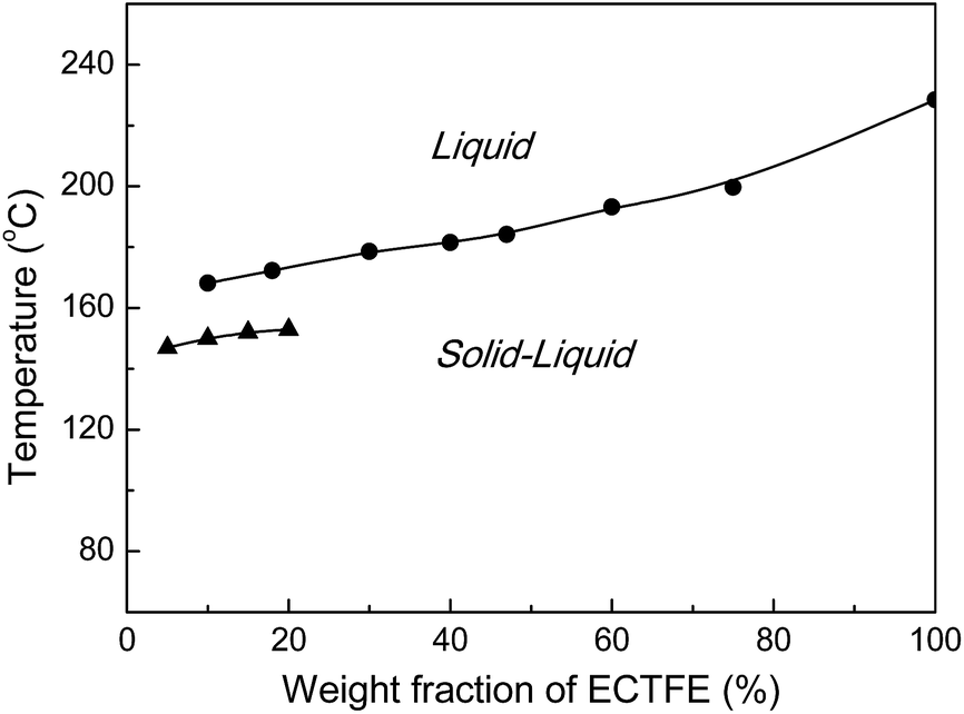 | ||
| Fig. 1 Experimentally determined binary equilibrium phase diagram for the ECTFE–DOA system. The liquid–liquid and solid–liquid region boundaries are obtained via cloud-point (▲) and DSC (●) experiments, respectively. Crystallization curves are obtained via DSC at cooling rates of 10 °C min−1. | ||
It is obvious that, the curve of crystallization points is higher than curve of cloud-points in the ECTFE–DOA system, which shows that the ECTFE–DOA system exhibits only a solid–liquid (S–L) phase-separation region without liquid–liquid (L–L) phase-separation region. The phase separation mechanism during cooling and membrane formation is affected by the different miscibility between the polymer/diluent systems. Looking at the ECTFE–DBP binary phase diagram, presented in ref. 9 and 21, it can be noticed that a liquid–liquid demixing area lies between the could-point curve and the crystallization curve for polymer concentration less than 25% (monotectic point). This suggests that, if polymer concentration is below this value, membrane formation should proceed via L–L demixing, which will take place before S–L demixing accompanied by polymer crystallization. On the contrary, in our case, since there is stronger affinity between the polymer and diluent, the mixture should undergo to S–L phase separation when cooled, as reported in literature.27
The cloud-points of solutions containing different polymer weight percentages can evaluate the solubility of ECTFE in DOA. In our case, the cloud-points are lower than those reported in literature for DBP or DEP.9,21,22 Therefore, the cloud-points curve shifts to lower temperatures when using DOA as solvent. As widely accepted in literature, the cloud-point temperature of a polymer/diluent system depends on the affinity between the two: the lower the cloud-point the more compatible are the two components. It also can be seen that, in our case, the crystallization points are lower than those reported in literature for DBP or DEP with different polymer weight percentages. So the area of homogeneous liquid phase can maintain at a lower temperature range before cooling to occur the S–L phase-separation, which giving the possibility of casting flat sheet membranes at temperature below 200 °C.
Morphology of membranes
In order to investigate the effect of polymer concentration on the membranes' morphology, a series of initial ECTFE concentrations are chosen: 20, 30, 40 and 50 wt%. Fig. 2 shows the morphologies of the ECTFE membranes fabricated with varied initial polymer concentrations. It can be observed that the increase of polymer fraction results in a decrease of pore size and surface porosity of the membranes. With the polymer concentration increasing, the density of the accumulation of spherulites increase, even fuse together, with only some interstices between them, and subsequent droplet growth of the diluents decrease, which, in turn, results in smaller pores. With increased solution viscosity at higher polymer concentrations, a significant decline in surface porosity is observed.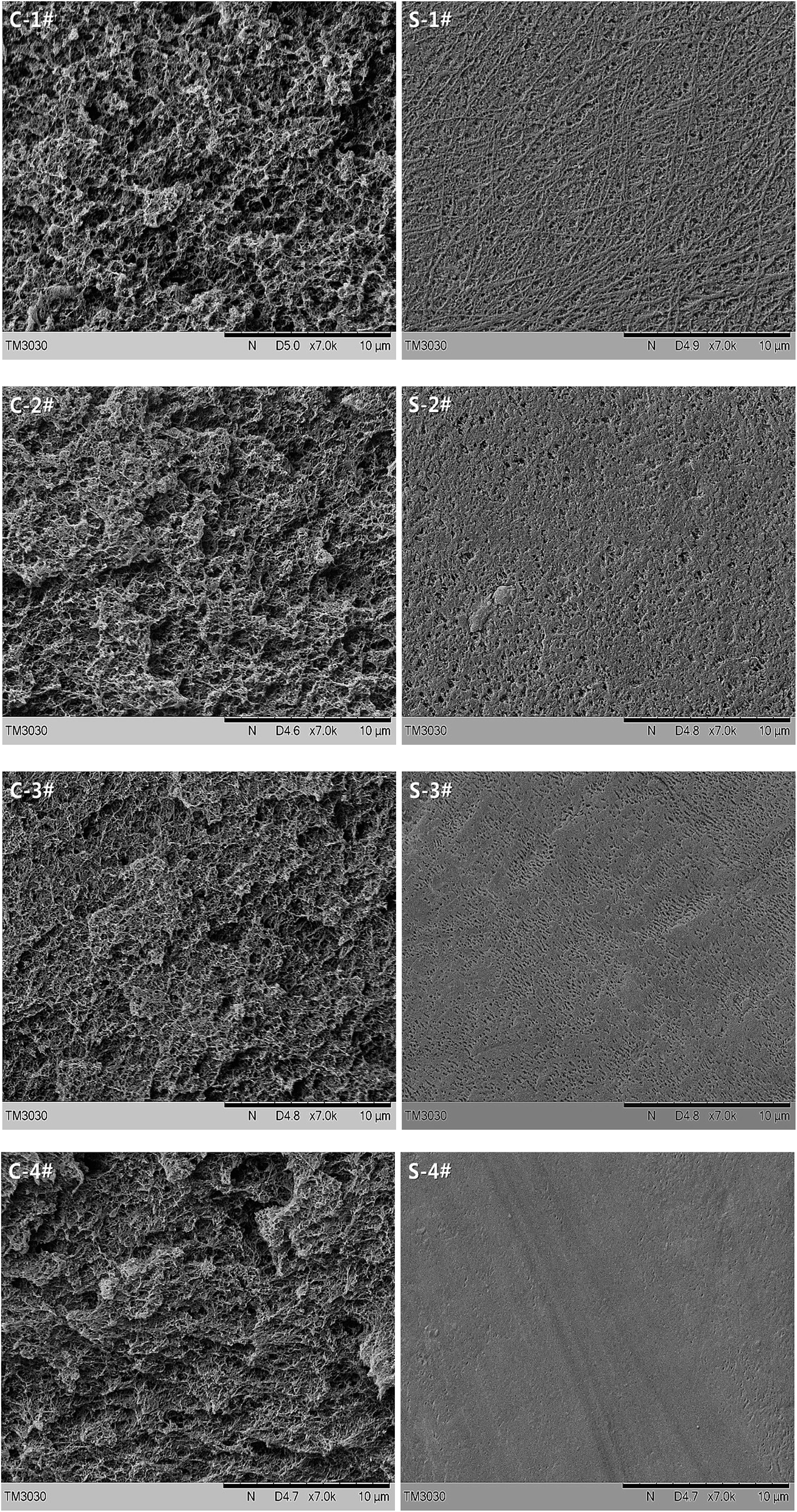 | ||
| Fig. 2 The morphologies of the ECTFE membranes with different initial ECTFE concentrations: (1#) 20 wt%, (2#) 30 wt%, (3#) 40 wt% and (4#) 50 wt%. Left: cross-section; right: surface (cooling rate = 10 °C min−1). | ||
It is well known, the formation of the skin layer of TIPS membranes depends on several factors including the cooling rate, the evaporation of diluent from the surface resulting in a high surface concentration of the polymer. In our case, the adding of PTFE films in the process of fabricating the membranes reduces the loss of diluent and minimizes the change of polymer fraction at the surface, combined with the relatively slow cooling rate (10 °C min−1), result in a similar isotropic membrane structure almost without the formation of a dense skin layer.
In order to explore the effect of additives on the microstructure of the membranes, the morphological changes between cross-sections and surfaces of the blend membranes are compared, while holding the initial ECTFE concentration at 30 wt%.
From the analysis of the cross sections of blend membranes shown in Fig. 3, it can be noticed that polymer spherulites become fine and uniform with the introduction of SiO2 particles, and the interfacial micro-voids form between polymer spherulites and SiO2 particles owing to the poor affinity between ECTFE and SiO2. The macrovoid-free structures can be obviously observed as adding the composite powder, which is because of the dissolved water-soluble particles. The surfaces of the membranes all show high porosity, attribute to non-existent of dense skin layer structure, especially the membrane blends with the composite powder.
 | ||
| Fig. 3 The morphologies of the blend membranes with 30 wt% ECTFE solution and blend with different additives: (2#) no additives, (5#) 4 wt% SiO2 particles, (6#) 4 wt% composite powder. Left: cross-section; right: surface. | ||
Permeation properties
The characterization of the obtained ECTFE membranes is tabulated in Table 2. It clearly illustrates that all the parameters decrease as polymer content rises. That is because the growth of diluent droplets is inhibited by polymer crystallization, higher the polymer content smaller the pores in membrane structure. |
Table 2 also shows the effect of additives on the characterization of the membranes (lines marked with shadow). Because of the formation of interfacial micropores between spherulites and SiO2 particles (5#) and the dissolved pores (6#), counteracting the porosity decreases resulting from the increase of polymer content, the porosity and PWF observed for the membranes blend with different additives do not differ significantly. However, the mean pore size decreases rapidly, means that the filtration precision of the membranes increase while keeping outstanding permeation properties.
Contact angle measurements
The water contact angle (CA) of the prepared ECTFE membranes is measured on the membrane surfaces. The average values are presented in Fig. 4. From Fig. 4, it can be noticed that the contact angle decreases slightly with increasing polymer content, nonetheless, increases obviously with the addition of SiO2 particles and composite powder. | ||
| Fig. 4 The water contact angle of the ECTFE membranes prepared in this study. | ||
These results can be explained taking into account the effect of porosity and roughness on the apparent contact angle of membrane surface. The apparent contact angle of a sessile droplet varies not only with the chemical texture of the surface, determined by the composition of the polymeric solution, but also with the roughness of the surface. In fact, the apparent contact angle is proportional to the ideal contact angle of the polymer and the surface roughness.28 In our case, the decrease of ECTFE membrane surface porosity smoothes the surface, which led to a slight decrease of the surface roughness. From the surface micrographs of the blend membranes shown in Fig. 3, we can see that the increase of porosity and roughness of surfaces are obvious.
Mechanical properties
The tensile strength of prepared ECTFE membranes is measured in order to study the effects of different additives on the mechanical properties. The obtained results are resumed in the plots presented in Fig. 5. With the addition of SiO2 particles (5#), the tensile strength increases, however, the elongation-at-break decreases. That is because, there is no strong affinity between ECTFE and inorganic particles due to the low surface energy of ECTFE. With the addition of the composite powder (6#), the presence of macropores leads to no obvious change of the tensile strength, but the further reduce of the elongation-at-break. | ||
| Fig. 5 Effect of the different additives on the mechanical properties of the ECTFE blend membranes, (2#) no additives, (5#) 4 wt% silica particles, (6#) 4 wt% composite powder. | ||
Moreover, we have also explored the effect of polymer concentration on the mechanical properties in this study, the result has not been presented in the above figure attributes to a traditional conclusion. That is, the tensile strength and elongation-at-break increase with the increasing polymer concentration.
Ultrafiltration performance
Fig. 6 shows the prepared ECTFE membranes' time-dependent pure water flux (Fig. 6(a)), rejection flux (Fig. 6(b)) and rejection ratio (Fig. 6(c)) to BSA protein solution, respectively. It is obvious that, the stable PWF and rejection flux of the ECTFE membranes with no additives decreases drastically with the increasing polymer content, while the rejection ratio increases obviously from 10% to 95%. With the increases of polymer content, the stacking of the spherulites becomes closer, the pores on the membrane surface becomes so smaller and less that the BSA cannot pass through the membrane. Combined with the protein spherical molecule gradually piles up on the hydrophobic membrane surface, the case of no flux may be appeared for the membranes with an excessive amount of polymer content, such as 4#.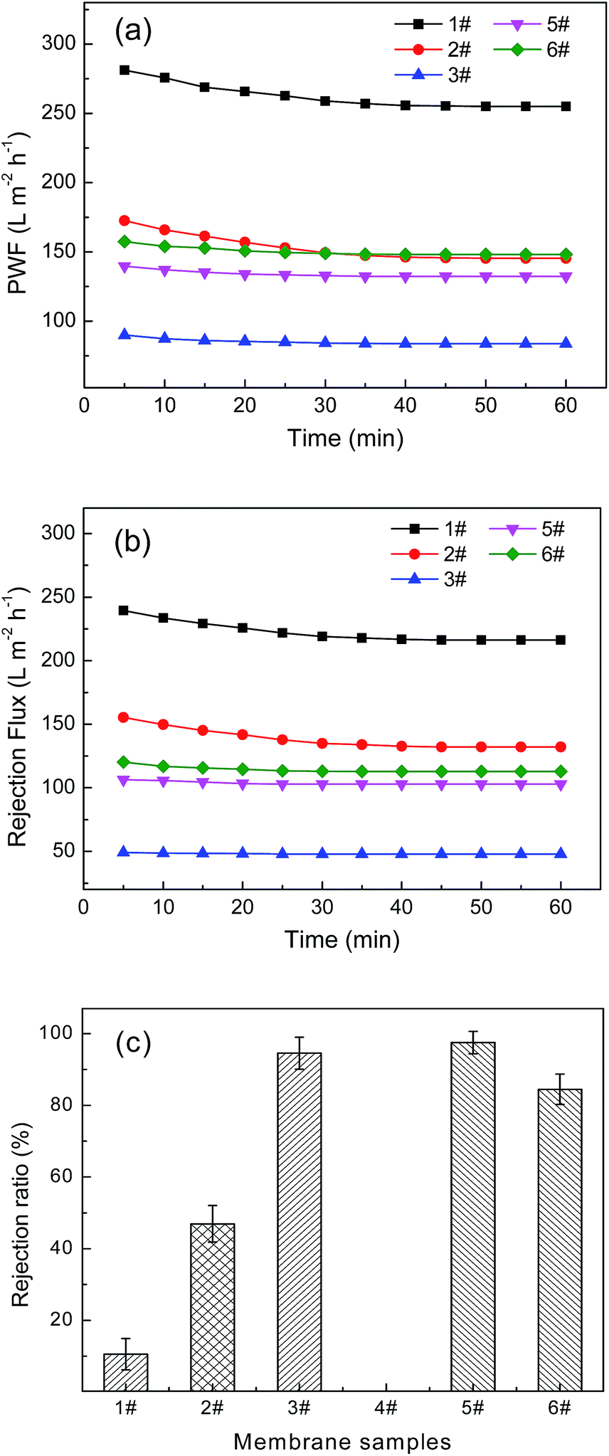 | ||
| Fig. 6 Rejection properties of the prepared ECTFE membranes to BSA protein solution (operation pressure 0.1 MPa): (a) pure water flux, (b) rejection flux, (c) rejection ratio. | ||
Moreover, Fig. 6 shows the additives have influence on filtrate flux and rejection ratio of BSA. In Fig. 6(b), the filtrate flux of BSA solution decrease as the addition of SiO2 particles and the composite powder. The reason may have two possible factors: one is the hindrance of insoluble inorganic particles, proved by the decrease of PWF shown in Fig. 6(a), another is the stacking of protein spherical molecule. Meanwhile, the presence of interfacial micropores (5#) and the dissolved pores (6#) is beneficial to enlarge the efficient filtration area, so the decreases are not as rapid as the changes of polymer content. Compared with the decrease of PWF and rejection flux, the increase of rejection ratio is more conspicuous and valuable. In Fig. 6(c), with the addition of SiO2 particles and the composite powder, the rejection ratio increase from 45% to 97% and 85%, respectively.
In addition, from Fig. 6(a) and (b), we can also see that, the PWF and rejection fluxes can reach stable in a short time and the decays are small. Which indicates that, the pore structure of the membranes has good pressure resistance.
Chemical resistant properties
The excellent chemical resistance is one of the most outstanding properties of ECTFE. The study of chemical resistance of prepared membranes can verify the possibility of applications in special chemical environments. In this study, we focus on the blend membrane samples with different additives, 2# is used to represent the membranes with varying polymer content.In Fig. 7, the effects of aggressive corrosive solutions on all the important properties of the prepared ECTFE membranes have been studied. It is obvious that, the strong alkaline and oxidizing solutions almost have no influence on the membranes blend with composite powder (6#) and the membranes with no additives (2#) represented all the membranes with different polymer contents (1–4#).
 | ||
| Fig. 7 Effect of different chemical reagents on the mechanical, permeation and filtration properties of the prepared ECTFE membranes immersed in NaOH (10000 ppm) and NaClO (10000 ppm) solution respectively for about half month: (a) tensile strength, (b) PWF, (c) rejection flux, (d) rejection ratio. | ||
For the membranes with SiO2 particles (5#), the effect of NaClO solution is also unconspicuous. While after immersed in NaOH solution for so long time that the filtration properties are affected. That is because SiO2 is a kind of acidic oxides, immersed in a strong alkaline solution for a long time it would be dissolved into the solution. The emergence of dissolved macropores results in the decrease of rejection ratio, but still keeping a relative high value (Fig. 7(d)). In conclusion, the prepared ECTFE membranes show excellent chemical resistance.
Conclusions
ECTFE flat sheet membranes have been successfully prepared using DOA as solvent, micro-scale SiO2 particles and composite powder as additives. The use of DOA allowed to prepared ECTFE solutions at temperatures below 200 °C, the addition of micro-sized silica particles and the composite powder brought about interfacial microvoids and a dissolved pore structure in the membrane. The results show that the obtained membrane is a kind of homogeneous membrane, with a porous skin layer. Membranes show a porous sponge-like morphology, high porosity and hydrophobicity. With the increase of polymer content, the mean pore size, porosity, pure water flux and protein solution flux decrease, while the protein rejection ratio and mechanical properties increase. With the addition of additives, the high porosity and mechanical properties of the prepared blend membranes are maintained, while the hydrophobicity and protein rejection ratio improved obviously. The prepared membranes also show good resistance to the aggressive chemical corrosive solutions.Acknowledgements
The authors gratefully acknowledge the financial support of the National Basic Research Program of China (2012CB722706) and the National Natural Science Foundation of China (21404079).References
- M. A. Shannon, P. W. Bohn, M. Elimelech, J. G. Georgiadis, B. J. Marinas and A. M. Mayes, Science and technology for water purification in the coming decades, Nature, 2008, 452, 301–310 CrossRef CAS PubMed.
- B. E. Logan and M. Elimelech, Membrane-based processes for sustainable power generation using water, Nature, 2012, 488, 313–319 CrossRef CAS PubMed.
- Z. L. Cui, E. Drioli and Y. M. Lee, Recent progress in fluoropolymers for membranes, Prog. Polym. Sci., 2014, 39, 164–198 CrossRef CAS PubMed.
- C. Wang, C. F. Xiao, Q. L. Huang and J. Pan, A study on structure and properties of poly(p-phenylene terephthamide) hybrid porous membranes, J. Membr. Sci., 2015, 474, 132–139 CrossRef CAS PubMed.
- M. M. Pendergast and E. M. V. Hoek, A review of water treatment membrane nanotechnologies, Energy Environ. Sci., 2011, 4, 1946–1971 CAS.
- Q. L. Huang, C. F. Xiao, X. Y. Hu and S. L. An, Fabrication and properties of poly(tetrafluoroethylene-co-hexafluoropropylene) hollow fiber membranes, J. Mater. Chem., 2011, 21, 16510–16516 RSC.
- J. G. Drobny, Technology of fluoropolymers, CRC Press, New York, 2nd edn, 2009 Search PubMed.
- Anonymous, Halar® ECTFE ethylene-chlorotrifluoroethylene design and processing guide, htpp://www.solvaysolexis.com, 2012 accessed Nov 2012.
- J. Roh, S. Ramaswamy, W. B. Krantzc and A. R. Greenberg, Poly(ethylene chlorotrifluoroethylene) membrane formation via thermally induced phase separation(TIPS), J. Membr. Sci., 2010, 362, 211–220 CrossRef PubMed.
- H. J. Müller, A new solvent resistant membrane based on ECTFE, Desalination, 2006, 199, 191–192 CrossRef PubMed.
- B. Zhou, Y. K. Lin, W. Z. Ma, Y. Tian and X. L. Wang, ECTFE membranes prepared via thermally induced phase separation-selection of mixed diluent, Membr. Sci. Technol., 2013, 33, 27–33 CAS.
- J. J. Kim, J. R. Hwang, U. Y. Kim and S. S. Kim, Operation parameters of melt spinning of polypropylene hollow fiber membranes, J. Membr. Sci., 1995, 108, 25–36 CrossRef CAS.
- H. Matsuyama, H. Okafuji, T. Mali, M. Teramoto and N. Kubota, Preparation of polyethylene hollow fiber membrane via thermally induced phase separation, J. Membr. Sci., 2003, 223, 119–126 CrossRef CAS.
- M. H. Razzaghi, A. Safekordi, M. Tavakolmoghadam, F. Rekabdar and M. Hemmati, Morphological and separation performance study of PVDF/CA blend membranes, J. Membr. Sci., 2014, 470, 547–557 CrossRef PubMed.
- M. Shang, H. Matsuyama, M. Teramoto, D. R. Lloyd and N. Kubota, Preparation and membrane performance of polyethylene-co-vinyl alcohol hollow fiber membrane via thermally induced phase separation, Polymer, 2003, 44, 7441–7447 CrossRef CAS PubMed.
- A. H. Cui, Z. Liu, C. F. Xiao and Y. F. Zhang, Effect of micro-sized SiO2-particle on the performance of PVDF blend membranes via TIPS, J. Membr. Sci., 2010, 360, 259–264 CrossRef CAS PubMed.
- Y. Su, C. X. Chen, Y. G. Li and J. D. Li, PVDF membrane formation via thermally induced phase separation, J. Macromol. Sci., Part A: Pure Appl.Chem., 2007, 44, 99–104 CrossRef CAS PubMed.
- G. L. Ji, C. H. Du, B. K. Zhu and Y. Y. Xu, Preparation of porous PVDF membrane via thermally induced phase separation with diluent mixture of DBP and DEHP, J. Appl. Polym. Sci., 2007, 105, 1496–1502 CrossRef CAS PubMed.
- Y. Mutoh and M. Miura, Porous fluorine resin membrane and process for preparing the same, US Pat. 4702836, 1987.
- D. Mullette and H. J. Muller, Poly(ethylene chlorotrifluoroethylene) membranes, US Pat. 7632439 B2, 2009.
- S. Ramaswamy, A. R. Greenberg and W. B. Krantz, Fabrication of poly(ECTFE) membranes via thermally induced phase separation, J. Membr. Sci., 2002, 210, 175–180 CrossRef CAS.
- B. Zhou, Y. K. Lin, W. Z. Ma, Y. H. Tang, Y. Tian and X. L. Wang, Preparation of ethylene chlorotrifluoroethylene co-polymer membranes via thermally induced phase separation, Chem. J. Chin. Univ., 2012, 33, 2585–2590 CAS.
- S. Simone, A. Figoli, S. Santoro, F. Galiano, S. M. Alfadul, Omar A. Al-Harbi and E. Drioli, Preparation and characterization of ECTFE solvent resistant membranes and their application in pervaporation of toluene–water mixtures, Sep. Purif. Technol., 2012, 90, 147–161 CrossRef CAS PubMed.
- E. Drioli, S. Santoro, S. Simone, G. Barbieri, A. Brunetti, F. Macedonio and A. Figoli, ECTFE membrane preparation for recovery of humidified gas streams using membrane condenser, React. Funct. Polym., 2014, 79, 1–7 CrossRef CAS PubMed.
- Y. Lin, Y. Tang, H. Ma, J. Yang, Y. Tian, W. Ma and X. Wang, Formation of a bicontinuous structure membrane of polyvinylidene fluoride in diphenyl carbonate diluent via thermally induced phase separation, J. Appl. Polym. Sci., 2009, 114, 1523–1528 CrossRef CAS PubMed.
- G. Ji, L. Zhu, B. Zhu, C. Zhang and Y. Xu, Structure formation and characterization of PVDF hollow fiber membrane prepared via TIPS with diluent mixture, J. Membr. Sci., 2008, 319, 264–270 CrossRef CAS PubMed.
- X. Li, G. Xu, X. Lu and C. Xiao, Effects of mixed diluent compositions on poly(vinylidene fluoride) membrane morphology in a thermally induced phase-separation process, J. Appl. Polym. Sci., 2008, 107, 3630–3637 CrossRef CAS PubMed.
- R. N. Wenzel, Resistance of solid surfaces to wetting by water, Ind. Eng. Chem., 1936, 28, 988–994 CrossRef CAS.
| This journal is © The Royal Society of Chemistry 2015 |