The effect of NaF on the electrochemical behavior of the Mg–11Li–3.5Al–1Zn–1Sn–1Ce–0.1Mn electrode in NaCl solution

Yanzhuo Lv*, Dandan Tang, Dianxue Cao, Guiling Wang, Milin Zhang and Jing Feng
Key Laboratory of Superlight Material and Surface Technology of Ministry of Education, College of Material Science and Chemical Engineering, Harbin Engineering University, Harbin 150001, P. R. China. E-mail: lvyanzhuo@hrbeu.edu.cn; Tel: +86-13845079693

Received 28th March 2015 , Accepted 12th May 2015

First published on 15th May 2015


Abstract

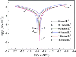
In order to improve the electrochemical behavior of the Mg–11Li–3.5Al–1Zn–1Sn–1Ce–0.1Mn electrode in a 0.7 mol L−1 NaCl solution, different concentrations of sodium fluoride (NaF) as the electrolyte additive are added into the electrolyte solution and their effects on the electrochemical performances of the electrode are investigated by the methods of potentiodynamic polarization, potentiostatic oxidation, electrochemical impedance spectroscopy (EIS) and scanning electron microscopy (SEM) with EDS analysis. It is found that the corrosion current density of the electrode decreases with the concentration of NaF in the following order: 0.5 mmol L−1 > 0.1 mmol L−1 > 1.0 mmol L−1 > 2.0 mmol L−1 > 0.8 mmol L−1 > 0 mmol L−1. The discharge current density of the electrode in the electrolyte solution containing 0.8 mmol L−1 NaF is higher than that in the other concentrations at the discharging potentials of −0.8 V, −1.0 V and −1.2 V. The electrode in the electrolyte solution containing 0.8 mmol L−1 NaF retains a larger reaction surface area during discharge, which leads to the highest discharge activity. The different concentrations of NaF in the 0.7 mol L−1 NaCl electrolyte solution can change the electrochemical behavior of the Mg–11Li–3.5Al–1Zn–1Sn–1Ce–0.1Mn electrode, and the optimum concentration of the electrolyte additive NaF is 0.8 mmol L−1. The Mg–H2O2 semi-fuel cell with the Mg–11Li–3.5Al–1Zn–1Sn–1Ce–0.1Mn anode presents a maximum peak power density of 77 mW cm−2 when it is measured in a 0.7 mol L−1 NaCl solution containing 0.8 mmol L−1 NaF as the anolyte at room temperature, which is higher than that measured in a 0.7 mol L−1 NaCl solution as the anolyte (62 mW cm−2). NaF is an effective anolyte additive for the Mg–11Li–3.5Al–1Zn–1Sn–1Ce–0.1Mn alloy electrode in Mg–H2O2 semi-fuel cells.


1. Introduction

Magnesium–hydrogen peroxide (Mg–H2O2) semi-fuel cells have been studied as power sources for unmanned underwater vehicles (UUV).1–7 Magnesium and its alloys, which are used as anode materials for undersea primary and reserve batteries, have various favorable characteristics, such as high energy density, high electrode potential (−2.37 V vs. SHE), low density (∼1.7 g cm−3), and environmental friendliness.1,8 However, currently the Mg–H2O2 semi-fuel cell is still not as popular as the Al–H2O2 semi-fuel cell. The major problem is that magnesium alloy electrodes undergo a parasitic corrosion reaction or self-discharge reaction, resulting in the reduction of coulombic efficiency and the evolution of hydrogen.9,10 Magnesium alloy electrodes operate at significantly less negative potential because of the passive oxide films on the magnesium alloy surface, which cause a delay in reaching a steady-state and a reduction in discharging rate. These disadvantages have delayed the development of Mg–H2O2 semi-fuel cell and limited its commercial exploitation.

There are in general two ways to improve the magnesium alloy anode performances. One is to dope the magnesium alloy with other elements, such as aluminum, zinc, silver, silicon, cadmium, and rare earth (RE) elements.11 The second is to modify the electrolyte by including additives. Both methods can inhibit the formation and accelerate the elimination of oxide layers and suppress corrosive dissolution.12,13 In the alloying process, doping the magnesium and magnesium alloy with other elements have been studied.14 Cao et al.9,10,15 reported that Mg–Li-based alloys exhibited high electro-oxidation activity in 0.7 mol L−1 NaCl solution. They found that Ce can enhance both the discharge activity and utilization efficiency of the electrode. Sn mainly improves the discharge current of the electrode. Our group17 found that Y can change the alloy structure16,17 or assist the formation of an easy-peel off layer on the alloys surface. The content of Zn in the alloys obviously affects the alloy performance and the Zn content of 0.5 wt% is better than 1 wt%.18 The main role of Mn is to improve the corrosion resistance and activity of magnesium alloy.10 The addition of Mn can enhance both current efficiency and discharge activity. Cao et al.9 investigated the effects of the electrolyte additive of Ga2O3 on the discharge performances of the Mg, Mg–Li, Mg–Li–Al and Mg–Li–Al–Ce electrodes. It has been found that Ga2O3 electrolyte additive can enhance the discharge currents and utilization efficiencies of the electrode. The utilization efficiency of the quaternary Mg–Li–Al–Ce electrode reached to as high as around 82% and 88% in the absence and presence of gallium oxide additive, respectively. Wan et al.19 found that adding Na2MoO4 into a phosphate solution with a high content NaF can significantly improve the corrosion resistance and joint strength of the magnesium AZ31 alloy.

In this study, in order to investigate the effect of the electrolyte additive of sodium fluoride (NaF) on the electrochemical behaviors of the Mg–11Li–3.5Al–1Zn–1Sn–1Ce–0.1Mn electrode in NaCl solution, the electrochemical behaviors of the Mg–11Li–3.5Al–1Zn–1Sn–1Ce–0.1Mn electrode in 0.7 mol L−1 NaCl solution with different concentrations (0.0 mmol L−1, 0.1 mmol L−1, 0.5 mmol L−1, 0.8 mmol L−1, 1.0 mmol L−1, 2.0 mmol L−1) of NaF were investigated. The Mg–H2O2 semi-fuel cell with nickel foam-supported Pd as cathode and 0.5 mol L−1 H2O2 + 0.1 mol L−1 H2SO4 + 0.7 mol L−1 NaCl as cathodic electrolyte and Nafion-115 as membrane was assembled and its electrochemical performances were investigated.

2. Experimental

2.1. Preparation of the Mg–11Li–3.5Al–1Zn–1Sn–1Ce–0.1Mn alloy

The alloy in this study was prepared by induction melting method. The materials used in this work were commercial pure ingots magnesium (99.99%), lithium (99.99%), aluminum (99.99%), zinc (99.99%), stannum (99.99%), manganese (99.99%) and Mg–Ce alloy containing 26.6 wt% Ce. As reported,16,18,21 the induction furnace with a refractory lined crucible surrounded by an induction coil is located inside a vacuum chamber. The induction furnace was linked to an AC power source at a frequency precisely matched to the furnace size and then the alloy was melted under the protection of ultrahigh purity argon. The furnace was then evacuated to 1.0 × 10⁻² Pa, and charged with ultrahigh purity argon. A preheated tundish-casting mold assembly was inserted through a valve. The refractory tundish was positioned in front of the induction furnace. The molten alloys were then poured through a tundish into a stainless steel cylinder with the inner diameter of 6 cm and the height of 18 cm. The mold containing hot melts was cooled down to environmental temperature under argon atmosphere in the furnace. The nominal compositions of the Mg–11Li–3.5Al–1Zn–1Sn–1Ce–0.1Mn alloy are given in Table 1.
Table 1 Chemical compositions of alloys (wt%)
Alloys Mg Li Al Zn Sn Ce Mn
Mg–11Li–3.5Al–1Zn–1Sn–1Ce–0.1Mn 82.4 11 3.5 1 1 1 0.1


2.2. Fuel cell tests

A home-made flow through test cell made of Plexiglas was used for examining the performance of the Mg–11Li–3.5Al–1Zn–1Sn–1Ce–0.1Mn alloy. The Mg–Li-based alloy was used as anode and nickel foam-supported Pd was used as cathode. Nafion-115 membrane was used to separate the anode and the cathode compartments. The anolyte (0.7 mol L−1 NaCl) and catholyte (0.5 mol L−1 H2O2 + 0.1 mol L−1 H2SO4 + 0.7 mol L−1 NaCl) were poured by peristaltic pump into the surface of anode and cathode, respectively, and flowed through electrode then outflowed from the exit upside. The flow rate for the anolyte and the catholyte were 80 mL min−1. The geometrical area of the Mg–Li-based alloy anode and the nickel foam-supported Pd cathode were 4.0 cm−2 (2.0 cm × 2.0 cm).

2.3. Electrochemical measurements

A specifically designed home-made three-electrode electrochemical cell18 was used. The cell was equipped with a platinum counter electrode, a saturated calomel reference electrode (SCE), and the Mg–11Li–3.5Al–1Zn–1Sn–1Ce–0.1Mn alloy working electrode. The working electrode was prepared as follows. The surface of the Mg–11Li–3.5Al–1Zn–1Sn–1Ce–0.1Mn alloy was successively polished with 600#, 1000# and 2000# metallographic emery papers in order to make the surface smooth and remove the original oxide films on the metal surface. Then, the electrode was washed with deoxygenated ultrapure water (Milli-Q), soaked in acetone for 15 minutes to eliminate the surface grease. Finally, it was rinsed with distilled water. The dimension of the Mg–11Li–3.5Al–1Zn–1Sn–1Ce–0.1Mn electrode is 20 mm × 20 mm × 2 mm and the geometric surface area is about 0.5 cm2. Electrochemical experiments were carried out in 0.7 mol L−1 NaCl solution with different concentrations of NaF at room temperature. The solution was purged with N2 gas for 15 minutes before measurements in order to remove the dissolved O2. During the measurements, N2 was flowed above the solution.

Electrochemical measurement techniques include potentiodynamic polarization (5 mV s−1, −2.2 V to −0.8 V), potentiostatic oxidation (15 min, at −0.8 V, −1.0 V, and −1.2 V), and electrochemical impedance spectroscopy (0.1 to 105 Hz, 5 mV, −1.0 V).

2.4. Characterizations of the alloy

The surface morphology of the Mg–11Li–3.5Al–1Zn–1Sn–1Ce–0.1Mn electrode after the test of potentiostatic oxidation was measured with scanning electron microscopy (SEM, JEOL JSM-6480).

3. Results and discussion

3.1. Potentiodynamic polarization

Fig. 1 shows the potentiodynamic polarization curves of the Mg–11Li–3.5Al–1Zn–1Sn–1Ce–0.1Mn electrode measured in 0.7 mol L−1 NaCl solution with different concentrations of NaF.
image file: c5ra05512a-f1.tif
Fig. 1 The potentiodynamic polarization curves of the Mg–11Li–3.5Al–1Zn–1Sn–1Ce–0.1Mn electrode in 0.7 mol L−1 NaCl solution containing different concentrations of NaF with the scanning rate of 5 mV s−1.

It can be observed from Fig. 1 that the presence of different concentrations of NaF in 0.7 mol L−1 NaCl solution can change the corrosion current density of the samples. The corrosion current density of the Mg–11Li–3.5Al–1Zn–1Sn–1Ce–0.1Mn electrode in 0.7 mol L−1 NaCl solution (2.414 mA cm−2, the additive concentration of 0.0 mmol L−1) is larger than that of the additive concentrations of 0.1 mmol L−1 (1.773 mA cm−2), 0.5 mmol L−1 (1.417 mA cm−2), 0.8 mmol L−1 (1.984 mA cm−2) 1.0 mmol L−1 (1.775 mA cm−2) and 2.0 mmol L−1 (1.874 mA cm−2), implying that the Mg–11Li–3.5Al–1Zn–1Sn–1Ce–0.1Mn electrode in 0.7 mol L−1 NaCl solution without the electrolyte additive is less corrosion resistant than that in the electrolyte solution containing the concentrations of NaF were 0.1 mmol L−1, 0.5 mmol L−1, 0.8 mmol L−1, 1.0 mmol L−1 and 2.0 mmol L−1. The corrosion resistance decreases as the following order: 0.5 mmol L−1 > 0.1 mmol L−1 > 1.0 mmol L−1 > 2.0 mmol L−1 > 0.8 mmol L−1 > 0 mmol L−1.

3.2. Potentiostatic measurements

Fig. 2a–c show the potentiostatic oxidation curves of the Mg–11Li–3.5Al–1Zn–1Sn–1Ce–0.1Mn electrode under different potentials of −0.8 V, −1.0 V and −1.2 V in 0.7 mol L−1 NaCl solution with different concentrations of NaF. Table 2 shows the current density at different discharge voltages of Mg–8Li–0.5Zn alloy electrode and Mg–11Li–3.5Al–1Zn–1Sn–1Ce–0.1Mn alloy electrode.
image file: c5ra05512a-f2.tif
Fig. 2 The current–time curves of the Mg–11Li–3.5Al–1Zn–1Sn–1Ce–0.1Mn electrode measured in 0.7 mol L−1 NaCl solution containing different concentrations of NaF at (a) −0.8 V, (b) −1.0 V and (c) −1.2 V.
Table 2 Current density at different discharge voltages of Mg–8Li–0.5Zn alloy electrode and Mg–11Li–3.5Al–1Zn–1Sn–1Ce–0.1Mn alloy electrode
Alloys Current density/mA cm−2
−0.8 V −1.0 V −1.2 V
Mg–8Li–0.5Zn 29.75 22.53 16.12
Mg–11Li–3.5Al–1Zn–1Sn–1Ce–0.1Mn 55.57 41.04 26.42


It can be seen from the three images, most of the current–time curves are smoothly except the (b) (0.1 mmol L−1 NaF) of Fig. 2c. The currents fluctuated periodically might be attributed to the accumulation and shedding of oxidation products.10 The oxidation products formed during the discharging, attached on the alloy surface, blocked the alloy surface from contact with the electrolyte, leading to the decrease of the active electrode surface area. When the oxides came off, the electrode surface area was uncovered, and the discharge currents increased. Compared with the previous related work we have ever reported,20 the current density in this study was greatly improved under the same working voltage. The detailed comparison is shown in Table 2. It can be seen from the table that under the voltage of −0.8 V, −1.0 V and −1.2 V, the current density is increased by 87%, 82% and 64%, respectively. From Fig. 2 above, the discharge current density of the electrode decreases with the concentration of NaF at −0.8 V and −1.0 V as the following order: 0.8 mmol L−1 > 0.0 mmol L−1 > 2.0 mmol L−1 > 0.5 mmol L−1 > 1.0 mmol L−1 > 0.1 mmol L−1, and the discharge current density of the electrode decreases with the concentration of NaF at −1.2 V as the following order: 0.8 mmol L−1 > 1.0 mmol L−1 > 0.0 mmol L−1 > 0.1 mmol L−1 > 2.0 mmol L−1 > 0.5 mmol L−1. The three images all lead to the conclusion that the discharge current density is the highest when the concentration of NaF in 0.7 mol L−1 NaCl solution is 0.8 mmol L−1, indicating that the optimum concentration of the electrolyte additive of NaF is 0.8 mmol L−1.

For the convenience of comparison, Fig. 3a and b show the discharge behaviors of the Mg–11Li–3.5Al–1Zn–1Sn–1Ce–0.1Mn electrode under different potentials of −0.8 V, −1.0 V and −1.2 V in 0.7 mol L−1 NaCl solution and in 0.7 mol L−1 NaCl solution with 0.8 mmol L−1 NaF.


image file: c5ra05512a-f3.tif
Fig. 3 The current–time curves of the Mg–11Li–3.5Al–1Zn–1Sn–1Ce–0.1Mn electrode recorded in (a) 0.7 mol L−1 NaCl solution and (b) 0.7 mol L−1 NaCl solution with 0.8 mmol L−1 NaF at various anodic potentials.

The discharge current density of the Mg–11Li–3.5Al–1Zn–1Sn–1Ce–0.1Mn electrode in 0.7 mol L−1 NaCl solution containing 0.8 mmol L−1 NaF is around 3 mA cm−2, 4 mA cm−2 and 6 mA cm−2 higher than that in 0.7 mol L−1 NaCl solution at the discharging potentials of −0.8 V −1.0 V and −1.2 V, respectively, indicating that the Mg–11Li–3.5Al–1Zn–1Sn–1Ce–0.1Mn electrode in 0.7 mol L−1 NaCl solution containing 0.8 mmol L−1 NaF is more electro-active than that in 0.7 mol L−1 NaCl solution. It can be concluded that the presence of 0.8 mmol L−1 NaF in NaCl electrolyte solution can best improve the discharge current density of the electrode.

Fig. 4 shows the electrochemical impedance spectra of the Mg–11Li–3.5Al–1Zn–1Sn–1Ce–0.1Mn electrode recorded at −1.0 V in 0.7 mol L−1 NaCl solution (or with 0.8 mmol L−1 NaF) after discharging 15 minutes in 0.7 mol L−1 NaCl solution (or with 0.8 mmol L−1 NaF) at −1.0 V.


image file: c5ra05512a-f4.tif
Fig. 4 The impedance spectra of the Mg–11Li–3.5Al–1Zn–1Sn–1Ce–0.1Mn electrode recorded at −1.0 V in 0.7 mol L−1 NaCl solution and in 0.7 mol L−1 NaCl solution with 0.8 mmol L−1 NaF after discharging 15 minutes in 0.7 mol L−1 NaCl solution with and without 0.8 mmol L−1 NaF at −1.0 V.

The Nyquist plots display a high frequency capacitive loop. The high frequency capacitive loop observed in the impedance spectra might result from both charge transfer and a surface oxide film, it can be seen from the figure that in the high frequency range, the loop of the electrode measures in 0.7 mol L−1 NaCl solution with 0.8 mmol L−1 NaF is smaller than that measures in 0.7 mol L−1 NaCl solution, which indicates that the electrode in 0.7 mol L−1 NaCl solution containing 0.8 mmol L−1 NaF has higher discharge activity. It can be understandable because the fast discharge in 0.7 mol L−1 NaCl solution with 0.8 mmol L−1 NaF lead to the easily breaking down and shedding of the oxide layers formed on the electrode surface during discharge. This result is consistent with the result obtained from SEM.

Fig. 5a and b show the SEM images of the Mg–11Li–3.5Al–1Zn–1Sn–1Ce–0.1Mn electrode after discharging at −1.0 V for 15 minutes in 0.7 mol L−1 NaCl solution and in 0.7 mol L−1 NaCl solution containing 0.8 mmol L−1 NaF, respectively.


image file: c5ra05512a-f5.tif
Fig. 5 SEM micrographs of the Mg–11Li–3.5Al–1Zn–1Sn–1Ce–0.1Mn electrode obtained after discharging 15 minutes in (a) 0.7 mol L−1 NaCl solution and (b) 0.7 mol L−1 NaCl solution with 0.8 mmol L−1 NaF at −1.0 V.

Fig. 5a indicates that the surface of the Mg–11Li–3.5Al–1Zn–1Sn–1Ce–0.1Mn electrode in 0.7 mol L−1 NaCl solution shows fine and even crackles. Fig. 5b demonstrates that the surface of the electrode after discharging in 0.7 mol L−1 NaCl solution containing 0.8 mmol L−1 NaF displays deeper and larger channels. Obviously, the discharging products of the electrode in different discharging environments show different morphologies on the surfaces. The deeper and larger channels on the surface allow the electrolyte to penetrate through and also allow the oxidation products to peel off more easily. As a result, the electrode in 0.7 mol L−1 NaCl solution containing 0.8 mmol L−1 NaF retains larger reaction surface area during discharge, which leads to the higher discharge activity.

Fig. 6a and b show the EDS analysis of the electrode products which discharged in the electrolyte solution without NaF and with 0.8 mmol L−1 NaF, respectively.


image file: c5ra05512a-f6.tif
Fig. 6 The EDS analysis for Mg–11Li–3.5Al–1Zn–1Sn–1Ce–0.1Mn electrode in 0.7 mol L−1 NaCl solution containing different concentrations of NaF: (a) 0.0 mmol L−1 (b) 0.8 mmol L−1.

It can be seen from Fig. 6a and b that the addition of NaF can change the content of the electrode products. On one hand, the content of Mg element decreases with the addition of NaF, indicating that more magnesium is converted to magnesium ions, so as to improve the utilization of the Mg electrode. On the other hand, the addition of NaF also leads to the decreasing of oxygen element, we infer from the result that NaF can make the oxidation products on the alloy surface easier to fall off, thus the electrode remains larger effective reaction area. The results further prove that NaF can improve the electrochemical activity of the anode.

3.3. Fuel cell performance

Fig. 7 and 8 show the voltage–current density curves and power density–current density curves of the Mg–11Li–3.5Al–1Zn–1Sn–1Ce–0.1Mn electrode measured in 0.7 mol L−1 NaCl solution and in 0.7 mol L−1 NaCl solution with 0.8 mmol L−1 NaF, respectively.
image file: c5ra05512a-f7.tif
Fig. 7 The voltage–current density curves of the Mg–H2O2 semi-fuel cell with the Mg–11Li–3.5Al–1Zn–1Sn–1Ce–0.1Mn alloy anode measured in (a) 0.7 mol L−1 NaCl solution and (b) 0.7 mol L−1 NaCl solution with 0.8 mmol L−1 NaF.

image file: c5ra05512a-f8.tif
Fig. 8 The power density–current density curves of the Mg–H2O2 semi-fuel cell with the Mg–11Li–3.5Al–1Zn–1Sn–1Ce–0.1Mn alloy anode measured in (a) 0.7 mol L−1 NaCl solution and (b) 0.7 mol L−1 NaCl solution with 0.8 mmol L−1 NaF.

It can be observed from Fig. 7 that both of the cell voltage decline linearly with the increase of current density, which may be associated with the ohmic resistance of the cell. The voltage of the cell with 0.7 mol L−1 NaCl solution containing 0.8 mmol L−1 NaF as the anolyte is slightly higher than that of the cell with 0.7 mol L−1 NaCl solution as the anolyte under the same current density which indicates that the addition of NaF into the anolyte can improve the discharge performances of the Mg–H2O2 semi-fuel cell with the Mg–11Li−3.5Al–1Zn–1Sn–1Ce–0.1Mn alloy as the anode. The peak power density of the semi-fuel cell with 0.8 mmol L−1 NaF in the anolyte reaches to 77 mW cm−2, which is higher than that without NaF in the anolyte (62 mW cm−2). The percentage of increase is 24%. So, the performances of the Mg–H2O2 semi-fuel cell with the Mg–11Li–3.5Al–1Zn–1Sn–1Ce–0.1Mn alloy as the anode has been increased with the addition of NaF into the anolyte and NaF is an effective electrolyte additive for the Mg–11Li–3.5Al–1Zn–1Sn–1Ce−0.1Mn anode which can promote its electrochemical performances.

4. Conclusions

The electrochemical oxidation behaviors of the Mg–11Li–3.5Al–1Zn–1Sn–1Ce–0.1Mn electrode in 0.7 mol L−1 NaCl solution with different concentrations of NaF (0.0 mmol L−1, 0.1 mmol L−1, 0.5 mmol L−1, 0.8 mmol L−1, 1.0 mmol L−1, 2.0 mmol L−1) were investigated. The preceding Results and discussion support the following conclusions.

(1) The presence of different concentrations of NaF in 0.7 mol L−1 NaCl solution changed the corrosion behaviors of the electrode. The corrosion resistive order decreases with the concentrations of NaF in the following sequence: 0.5 mmol L−1 > 0.1 mmol L−1 > 1.0 mmol L−1 > 2.0 mmol L−1 > 0.8 mmol L−1 > 0 mmol L−1.

(2) The discharge current density of the electrode in 0.7 mol L−1 NaCl solution with 0.8 mmol L−1 NaF is the highest among the added concentrations of the electrolyte additive under different potentials of −0.8 V, −1.0 V and −1.2 V.

(3) The peak power density of the semi-fuel cell with the Mg–11Li–3.5Al–1Zn–1Sn–1Ce–0.1Mn alloy as the anode reaches to 77 mW cm−2 measured in 0.7 mol L−1 NaCl solution containing 0.8 mmol L−1 NaF as the anolyte, which is higher than that in 0.7 mol L−1 NaCl solution as the anolyte (62 mW cm−2). The percentage of increase is 24%.

Acknowledgements

We show gratefully acknowledgements for the Natural Science Foundation of Heilongjiang Province of China (B201201), the National Natural Science Foundation of China (21203040, 21301038), China postdoctoral science foundation (Grant no. 2014M561357), the Fundamental Research Funds for the Central Universities (HEUCF20151004).

References

  1. M. G. Medeiros, R. R. Bessette, C. M. Deschenes, C. J. Patrissi, L. G. Carreiro, S. P. Tucker and D. W. Atwater, J. Power Sources, 2004, 136, 226–231 CrossRef CAS PubMed.
  2. R. R. Bessette, M. G. Medeiros, C. J. Patrissi, C. M. Deschenes and C. N. LaFratta, J. Power Sources, 2001, 96, 240–244 CrossRef CAS.
  3. R. R. Bessette, J. M. Cichon, D. W. Dischert and E. G. Dow, J. Power Sources, 1999, 80, 248–253 CrossRef CAS.
  4. W. Q. Yang, S. H. Yang, W. Sun, G. Q. Sun and Q. Xin, J. Power Sources, 2006, 160, 1420–1424 CrossRef CAS PubMed.
  5. D. J. Brodrecht and J. J. Rusek, Appl. Energy, 2003, 74, 113–124 CrossRef CAS.
  6. W. Q. Yang, S. H. Yang, W. Sun, G. Q. Sun and Q. Xin, J. Power Sources, 2006, 52, 9–14 CAS.
  7. O. Hasvold, N. J. Storkersen, S. Forseth and T. Lian, J. Power Sources, 2006, 162, 935–942 CrossRef CAS PubMed.
  8. M. C. Lin, C. Y. Tsai and J. Y. Uan, Corros. Sci., 2009, 51, 2463–2472 CrossRef CAS PubMed.
  9. D. X. Cao, L. Wu, Y. Sun, G. L. Wang and Y. Z. Lv, J. Power Sources, 2008, 177, 624–630 CrossRef CAS PubMed.
  10. D. X. Cao, L. Wu, G. L. Wang and Y. Z. Lv, J. Power Sources, 2008, 183, 799–804 CrossRef CAS PubMed.
  11. G. Liang, J. Alloys Compd., 2004, 370, 123–128 CrossRef CAS PubMed.
  12. Q. F. Li and N. J. Bjerrum, J. Power Sources, 2002, 110, 1–10 CrossRef CAS.
  13. R. Udhayan, N. Muniyandi and P. B. Mathur, J. Power Sources, 1991, 34, 303–312 CrossRef CAS.
  14. Y. Feng, R. C. Wang, K. Yu, C. Q. Peng, J. P. Zhang and C. Zhang, J. Alloys Compd., 2009, 473, 215–219 CrossRef CAS PubMed.
  15. D. X. Cao, X. Cao, G. L. Wang, L. Wu and Z. S. Li, J. Solid State Electrochem., 2010, 14, 851–855 CrossRef CAS.
  16. Y. Z. Lv, Y. Xu and D. X. Cao, J. Power Sources, 2011, 196, 8809–8814 CrossRef CAS PubMed.
  17. Y. Z. Lv, M. Liu and D. X. Cao, J. Power Sources, 2013, 239, 265–268 CrossRef CAS PubMed.
  18. Y. Z. Lv, M. Liu and D. X. Cao, J. Power Sources, 2013, 225, 124–128 CrossRef CAS PubMed.
  19. T. T. Wan, Z. X. Liu, M. Z. Bu and P. C. Wang, Corros. Sci., 2013, 66, 33–42 CrossRef CAS PubMed.
  20. Y. Z. Lv, D. D. Tang, D. Xu, Y. Z. Jin, Z. B. Wang, Y. F. Li, J. Feng, Y. M. Ren and D. X. Cao, RSC Adv., 2014, 4, 63182–63188 RSC.
  21. X. G. Meng, R. Z. Wu and M. L. Zhang, J. Alloys Compd., 2009, 486, 722–725 CrossRef CAS PubMed.

This journal is © The Royal Society of Chemistry 2015
Click here to see how this site uses Cookies. View our privacy policy here.