A comparative study of ordered mesoporous carbons with different pore structures as anode materials for lithium-ion batteries

Diganta Saikiaa, Tzu-Hua Wanga, Chieh-Ju Choua, Jason Fangb, Li-Duan Tsaib and Hsien-Ming Kao*a
aDepartment of Chemistry, National Central University, Chung-Li 32054, Taiwan, Republic of China. E-mail: hmkao@cc.ncu.edu.tw; Fax: +886-3-4227664; Tel: +886-3-4275054
bDepartment of Fuel Cell Materials and Advanced Capacitors, Division of Energy Storage Materials and Technology, Material and Chemical Laboratories, Industrial Technology Research Institute, Hsin-Chu 300, Republic of China

Received 24th March 2015 , Accepted 5th May 2015

First published on 5th May 2015


Abstract

In this study, ordered mesoporous carbons (OMCs) with different pore structures, namely 2D hexagonal CMK-3 and 3D cubic CMK-8 prepared by the nanocasting method using mesoporous silicas SBA-15 and KIT-6 as hard templates, respectively, in their pure forms are used as anode materials in lithium ion batteries (LIBs) to evaluate the role of mesoporous structures in their electrochemical performances. The results demonstrate that the CMK-8 electrode exhibits a higher reversible capacity and better cycling stability and rate capability, as compared to the CMK-3 electrode, due to its unique 3D cubic mesostructure. The initial capacities of 1884 and 964 mA h g−1 are obtained for the CMK-8 and CMK-3 electrodes, respectively. The CMK-8 electrode exhibits a higher capacity value (around 37.4% higher) than the CMK-3 electrode at the 100th cycle. The enhanced electrochemical performance of CMK-8 is mainly attributable to its unique 3D channel networks, which are beneficial for efficient Li storage and volume change. Although CMK-3 is the most investigated OMCs used in LIBs, herein we demonstrate that CMK-8 is a better carbon matrix for the fabrication of the electrode materials composed of mesoporous carbons.

Introduction

Rechargeable lithium-ion batteries (LIBs) are promising power sources that are currently used in many portable electronic devices and electric vehicles due to their high energy density, high operating voltage, low self-discharge, long cycle life and low toxicity.1–5 To date, graphite is still the most commonly used anode material in LIBs because of its desirable characteristics such as low cost, easy processability and chemical stability. However, the Li storage capacity of graphite is limited to 372 mA h g−1 due to the formation of LiC6 in the lithium-ion intercalation process, which greatly restricts the development of LIBs with high energy density.6 Other carbonaceous materials, in their various forms such as amorphous carbons, carbon nanotubes, carbon nanofibers, graphene and large porous carbon monoliths, have been extensively studied in order to achieve higher specific capacities.7–15 However, the high irreversible capacity due to the formation of solid electrolyte interface (SEI) layers is still a concern for using these materials as anodes in LIBs. To overcome this shortcoming and to further improve the LIB anode performance, much of the recent research has been focused on the incorporation of metal oxide nanoparticles (e.g., Co3O4, Fe3O4, SnO2, MoO2, TiO2 and others) into carbonaceous materials to integrate the advantages of metal oxides and carbons.16–25 Although it is considered to be a promising strategy, the development of new carbonaceous materials with favorable structural properties, such as morphology, crystallinity, and porosity, as ideal carbon matrices for the high performance of LIBs is highly desirable.

In recent years, ordered mesoporous carbons (OMCs), e.g., CMK-3, have gained more attention to be used as the anode materials in lithium-ion batteries due to their unique structural characteristics such as ordered mesoporous channels, high surface areas, large pore volumes and uniform pore size distribution.16,17,26 The ordered mesoporous channels and large surface areas of OMCs have the advantages to shorten the diffusion length of lithium ions. Moreover, their pore structures provide a continuous pathway for rapid transport of electrons, and thus exhibit high conductivities.27 Among various types of OMCs, the mesoporous carbon CMK-3, a reverse replica of mesoporous silica SBA-15 with a two-dimensional (2D) hexagonal pore structure, and its composites have become the most widely investigated electrode materials for LIBs.18,19,27 For example, Zhou et al. have tested the performance of CMK-3 in a three-electrode cell and obtained a high reversible specific capacity.27 Zhang et al. have prepared the CoO/CMK-3 composite by an infusing method and obtained a capacity value of 709 mA h g−1 after 20 cycles, in comparison to that of pure CMK-3 (350 mA h g−1).18 CMK-3 and SnO2/CMK-3 nanocomposites have been synthesized by the sonochemical method and achieved a reversible capacity of 546 mA h g−1 after 35 cycles, which was higher than pure CMK-3 (234 mA h g−1).19 When CMK-3 was modified with FeOx nanoparticles, it exhibited a reversible capacity of 320 mA h g−1 after 50 cycles, much higher than that of 50 mA h g−1 of the parent CMK-3 sample at high current density rate of 1600 mA g−1.20 Guo et al. have found that graphene-encapsulated ZnO/CMK-3 composite exhibited a better reversible capacity (650 mA h g−1) than the ZnO/CMK-3 composite (320 mA h g−1) after 100 cycles.28 It is believed that the mesopores of CMK-3 can suppress the growth of metal oxides particles and accommodate the volume change during lithium ion intercalation/deintercalation processes. On the other hand, CMK-8, a kind of three-dimensional (3D) cubic mesoporous carbon, can be prepared through a reverse replica of 3D cubic mesoporous silica KIT-6 (Ia3d symmetry) that consists of an interpenetrating bicontinuous network of channels.28 In comparison to CMK-3, little attention has been paid to the applications of CMK-8 and its composites in lithium-ion batteries. It will be of particular interest and significance, from the structural point of view, to compare electrochemical performance with the changes in pore arrangements of OMCs, which, to the best of our knowledge, has not been reported yet. The 2D hexagonal mesopores of CMK-3 and 3D cubic mesopores of CMK-8 make these materials very interesting to study the effects of pore arrangements on their electrochemical behaviors such as capacity, cycle efficiency, and rate capability, since the different mesopore arrangements of OMCs might have significant influences on the lithium ion transport properties. The goal of the present work is to perform a systematic analysis in order to understand the key structural parameters of CMK-3 and CMK-8, in their pure forms without incorporation of metal oxides, on their electrochemical performances in LIBs.

Experimental section

Materials

The triblock co-polymer EO20PO70EO20 (Pluronic P123), poly(vinylidene fluoride) (PVdF), tetraethyl orthosilicate (TEOS), HCl (36.5%) and H2SO4 (98%) were purchased from Aldrich. n-Butanol (99.4%) and sucrose were purchased from J. T. Baker. The electrolyte, 1 M LiPF6 in ethylene carbonate (EC)/diethyl carbonate (DEC) was acquired from Tomiyama Chemicals, Japan. KS6 graphite was purchased from Timcal. Lithium metal (Alfa Aesar) and N-methyl-2-pyrrolidone (NMP, Macron chemicals) were used as received.

Preparation of CMK-3 and CMK-8

To prepare the CMK-3 and CMK-8 by nanocasting, the mesoporous silica materials SBA-15 and KIT-6 were first synthesized according to the procedures reported in the literature,29,30 and then they were used as hard templates, respectively, by using sucrose as the carbon precursor.31,32 The overall synthesis routes and schematic representation of pore arrangements of CMK-3 and CMK-8 are illustrated in Scheme 1. To synthesize CMK-3, 1 g of SBA-15 and 1.25 g of sucrose were first dissolved in 6 g of deionized (DI) H2O. Then, 0.18 g of H2SO4 (98%) was added dropwise to the solution. After stirring for 1 h, the mixture was dried at 100 °C for 6 h and subsequently at 160 °C for another 6 h. The resulting product was impregnated again with an aqueous solution consisting of 0.75 g of sucrose, 4 g of DI H2O and 0.08 g of H2SO4, and thermally treated at 100 °C for 6 h and at 160 °C for another 6 h.
image file: c5ra05168a-s1.tif
Scheme 1 Schematic illustration of nanocasting synthesis of (A) CMK-3 and (B) CMK-8 and dispersion of lithium ions on these ordered mesoporous carbons.

For the synthesis of CMK-8, 1 g of KIT-6 and 1.25 g of sucrose were dissolved in 3 g of DI H2O to form a solution. Then, 0.15 g of H2SO4 was added dropwise to the solution and stirred for 1 h. The mixture was dried at 100 °C for 6 h and then at 160 °C for another 6 h. The impregnation process was repeated once as the case of CMK-3.

Both the resulting products were carbonized separately by treating them at 150 °C for 1 h and subsequently at 900 °C for 3 h under 5% H2/95% Ar atmosphere. Afterward, the silica template was removed by etching in 1 M NaOH (50 vol% DI H2O/50 vol% ethanol) at 90 °C for 24 h. Finally, CMK-3 and CMK-8 were obtained by filtration, washed with DI H2O several times, and dried at 60 °C.

Preparation of anodes and fabrication of batteries

The anode was prepared by blade-coating a slurry of 70 wt% OMC (either CMK-3 or CMK-8), 20 wt% KS6 and 10 wt% PVdF binder in NMP on copper foil, drying overnight at 100 °C in a vacuum oven, roller-pressing the dried coated foil, and punching out circular discs. Cell assembly was carried out in an Ar-filled glove box using a CR2032-type coin cell. Lithium metal was used as the counter and reference electrode. The polypropylene (PP) membrane was used as the separator while the electrolyte solution was 1 M LiPF6 in EC/DEC.

Characterization methods

Powder X-ray diffraction (XRD) patterns were recorded on PANalytical X'Pert Pro and Shimadzu LabX XRD-6000 X-ray diffractometers for small angle and wide angle measurements, respectively.

N2 adsorption–desorption isotherms were measured at 77 K on a Micromeritics ASAP 2020 analyzer. The samples were degassed at 150 °C for 10 h before the measurements. Specific surface areas were calculated by using the Brunauer–Emmett–Teller (BET) method in the relative pressure range of P/P0 = 0.05–0.3. The pore size distribution was obtained from the analysis of the desorption branch of the isotherm by using the Barrett–Joyner–Halenda (BJH) method. Pore volumes were obtained from the volume of N2 adsorbed at, or in the vicinity of, P/P0 = 0.95.

Raman scattering spectra were obtained from a UniRaman spectrometer (Protrustech Co. Ltd.) equipped with a 532 nm laser source. Scanning electron microscopy (SEM) was performed on a FEI Nova NanoSEM 230 field-emission electron microscope at an accelerating voltage of 10 kV. High resolution transmission electron microscopic (TEM) images were acquired on a JEOL JEM2100 electron microscope at an acceleration voltage of 200 kV. The particle size was measured by photon correlation spectroscopy by using a Zetasizer 300 laser particle analyzer (Malvern Instruments, UK) at 25 °C.

The galvanostatic charge–discharge performance was measured with WonATech WBCS3000 automatic battery cycler at room temperature in the voltage range of 0.01–3.0 V versus Li/Li+. Cyclic voltammetry (CV) studies were performed between 0.01 and 3.0 V at a scan rate of 0.1 mV s−1. Electrochemical impedance spectroscopy (EIS) measurements were carried out after 45 charge–discharge cycles in the frequency range of 1 MHz to 100 Hz with a zero-bias potential and 10 mV of amplitude using Bio-Logic SP-150 potentiostat/galvanostat at room temperature.

The cycled cells were disassembled in the glove box. The anodes based on CMK-3 and CMK-8 were washed with pure EC to remove the electrolyte. The washed electrodes were dried in vacuum to evaporate the EC. The morphology of the electrodes was observed by SEM (FEI Nova NanoSEM 230).

Results and discussion

Structural analysis

Small angle powder XRD patterns, as shown in Fig. S1 in ESI, are recorded to check the structural ordering of mesoporous silicas SBA-15 and KIT-6 that are employed as the hard templates for the synthesis of OMCs. Both the SBA-15 and KIT-6 samples show well resolved XRD peaks corresponding to p6mm and Ia3d symmetry, respectively, indicative of good quality of the template materials. After nanocasting, the small angle powder XRD patterns of the synthesized CMK-3 and CMK-8 samples are depicted in Fig. 1. The ordered mesoporous channels of CMK-3 give rise to the XRD peaks at 2θ = 1.1°, 1.8° and 2.1°, which correspond to the (100), (110) and (200) diffractions of 2D hexagonal mesostructure with the p6mm space group.32 On the other hand, the ordered structure of CMK-8 exhibits two XRD peaks at 2θ = 1.1° and 1.3°, corresponding to the (211) and (220) diffractions of a 3D cubic mesoporous structure with the Ia3d space group.30 Both XRD results confirm that the CMK-3 and CMK-8 structures are reverse replicas of SBA-15 and KIT-6, respectively. In the wide angle XRD patterns, both CMK-3 and CMK-8 exhibit two broad peaks around 2θ = 23° and 43°, corresponding to the (002) and (100) diffractions due to the graphitic structure. This confirms the presence of small amounts of stacked crystalline graphite phase in both CMK-3 and CMK-8.19,27
image file: c5ra05168a-f1.tif
Fig. 1 (A) Small angle and (B) wide angle XRD patterns of mesoporous carbons CMK-3 and CMK-8.

Textural properties

Nitrogen adsorption–desorption isotherm measurements were carried out to identify the mesoporous structures of SBA-15, KIT-6, CMK-3 and CMK-8. The adsorption–desorption isotherms and pore size distribution of the hard template materials SBA-15 and KIT-6 are shown in Fig. S2 (ESI). Both SBA-15 and KIT-6 show the characteristics of the type IV isotherms with H1 hysteresis loops according to the IUPAC classification, indicating the presence of mesoporous channels. The results of the textural properties of the hard templates SBA-15 and KIT-6 are summarized in Table 1. Fig. 2 shows the adsorption–desorption isotherms and pore size distribution of the CMK-3 and CMK-8 samples. Both the mesoporous carbon samples also exhibit typical type IV isotherms with H1 hysteresis loops, corresponding to mesoporous materials with ordered structures. The surface area, pore volume, and pore diameter of both samples are also listed in Table 1. It should be noted that both CMK-3 and CMK-8 possess high surface areas with similar values (1168 vs. 1131 m2 g−1) and large pore volumes with similar values (1.11 vs. 1.36 cm3 g−1). The adsorption isotherm over P/P0 of 0.8 of CMK-3 and CMK-8 suggests the presence of some interparticle pores or void spaces in the samples.33 The pore size distribution (PSD) curves of CMK-3 and CMK-8 reveal that their pore sizes are about 3.3 and 3.8 nm, respectively. In addition to the mesopores, a fraction of micropores formed during the carbonization of the carbon precursor. The micropore volume of both CMK-3 and CMK-8 is significantly low (0.05 vs. 0.06 cm3 g−1) compared to the mesopore volume (1.06 vs. 1.30 cm3 g−1), suggesting that the contribution to the electrochemical performance is mainly due to the mesopores, instead of the micropores, while they are used as anode materials.
Table 1 Textural parameters for mesoporous silicas and carbonsa
Sample SBET (m2 g−1) Vmeso (cm3 g−1) Vmicro (cm3 g−1) Vtotal (cm3 g−1) D (nm)
a SBET: surface area; Vmeso: mesopore volume; Vmicro: micropore volume; Vtotal: total pore volume; D: pore size.
SBA-15 717 1.01 0.04 1.05 6.2
KIT-6 819 1.03 0.07 1.1 6.5
CMK-3 1168 1.06 0.05 1.11 3.3
CMK-8 1131 1.3 0.06 1.36 3.8


image file: c5ra05168a-f2.tif
Fig. 2 N2 adsorption–desorption isotherms and pore-size distribution curves of CMK-3 and CMK-8.

Raman spectroscopy

Raman spectroscopy has been widely used to characterize the ordered and disordered structures of carbon materials as well as the layers of graphite. To gain more information on the carbon structure, Raman spectra of the mesoporous carbon materials CMK-3 and CMK-8 used in this study were measured and depicted in Fig. 3. Two prominent peaks are observed at 1324 and 1590 cm−1, corresponding to the D and G bands, respectively. The D band is related to the structural defects and partially disordered (amorphous) structures of the sp2 domains, while the G band indicates the sp2-bonded carbon–carbon stretching (E2g) vibration mode in a two-dimensional hexagonal lattice for graphene sheets.34 The peak intensity ratio between the D and G band (ID/IG) is usually used to measure the degree of in-plane defects, crystalline dimension and edge defects in the carbon materials.34,35 The commercial graphite exhibits an ID/IG value of 0.366.36 The ID/IG ratios for the CMK-3 and CMK-8 samples are 0.999 and 1.001, respectively. As the ID/IG values for CMK-3 and CMK-8 are much higher than the pure graphite, both the carbon materials reveal characteristics of nanocrystalline carbon with a low graphitization degree. The observation of low graphitic structures in CMK-3 and CMK-8 is consistent with the wide angle XRD results.
image file: c5ra05168a-f3.tif
Fig. 3 Raman spectra of mesoporous carbons CMK-3 and CMK-8.

Particle size and structure analysis

The morphologies and mesostructures of CMK-3 and CMK-8 are probed by SEM and TEM, respectively, and the results are shown in Fig. 4. The SEM image of CMK-3 (Fig. 4A) reveals the particle with a short rod shape with a length of ca. 1 μm. Moreover, the morphologies and dimensions of CMK-3 are relatively homogeneous. CMK-8, on the other hand, exhibits aggregated irregular spherical shape particles of size around 1 μm consisting of tiny particles (Fig. 4A). To verify the SEM results, dynamic light scattering (DLS) measurements are carried out on the CMK-3 and CMK-8 samples. The particle size distribution curves and the particle size measurements of the OMCs are shown in Fig. S3 (ESI). It is observed that the particle size of CMK-8 is around 615 nm (with a sharp distribution at 220 nm), which is smaller than that of CMK-3 (712 nm with a small shoulder near 250 nm). However, the larger size particles of ca. 5.6 μm are observed for both the OMCs due to partial aggregation of particles in water, which is the solvent used to disperse the samples. As the mesoporous carbons are hydrophobic in nature, aggregation of particles takes place easily in water. The particle size distribution results of OMCs are relatively consistent with the SEM observations. A highly ordered hexagonal array of uniform pore structure is clearly visible in the high resolution TEM images of CMK-3 (Fig. 4B). In the TEM image of CMK-8, on the other hand, a long-ranged ordered cubic mesostructure was observed. The mesostructure of CMK-8 consists of 3D cubic (Ia3d symmetry) mesoporous tube-like channels with interpenetrating bicontinuous network of channels. The pore sizes of both CMK-3 and CMK-8 obtained from the TEM images are in the range of 3.5–3.9 nm, which are in good agreement with the pore sizes determined from the nitrogen adsorption–desorption isotherm measurements.
image file: c5ra05168a-f4.tif
Fig. 4 SEM (A) and TEM (B) images of mesoporous carbons CMK-3 and CMK-8.

Cyclic voltammetry

Cyclic voltammetry (CV) measurements were carried out to explore the redox reactions with respect to the lithium insertion/extraction processes in the CMK-3 and CMK-8 anodes. Fig. 5 displays the CV data of the 1st, 5th and 10th cycles for CMK-3 and CMK-8 used as the anodes, which were measured over a potential range of 0.01–3.0 V at a scan rate of 0.1 mV s−1. For the CMK-3 electrode, three peaks at 0.90, 0.10, and 0.02 V were observed in the first cathodic scan. The reduction peak around 0.90 V is attributed to the electrolyte decomposition on the carbon material and the formation of solid electrolyte interphase (SEI) layer.36 The peak at 0.10 V is slightly shifted to 0.16 V in the subsequent cycles. The peak around 0.02–0.16 V corresponds to the insertion of lithium into the carbon. In the reverse anodic process, the oxidation peaks at 0.19 V and 0.26 V are ascribed to the extraction of lithium from carbon. The small oxidation peak around 1.2 V is attributed to the partial deposition of SEI.28 For the CMK-8 electrode, almost the same type of CV profiles was observed with the 1st cycle cathodic peaks at 0.78, 0.12, and 0.03 V. While the 0.78 V peak is related to the formation of SEI layer on the electrode, the peaks at ca. 0.03–0.12 V are ascribed to the lithium insertion into the carbon. In the anodic scan, the oxidation peaks observed around 0.17 V and 0.25 V are associated with the lithium extraction from carbon.
image file: c5ra05168a-f5.tif
Fig. 5 Cyclic voltammograms of CMK-3 and CMK-8 electrodes at a scan rate of 0.1 mV s−1.

The near overlapping of the peak positions, intensities, and integral areas in the 5th and 10th cycles suggests good reversibility and electrochemical stability of the CMK-3 and CMK-8 electrodes.

Charge–discharge performance

Electrochemical impedance spectroscopy (EIS) is an effective tool for exploring the interfacial processes and kinetics of electrode reactions in the electrochemical systems. Fig. 6 shows the Nyquist plots of the CMK-3 and CMK-8 electrode materials measured after 45 charge–discharge cycles. The simplified equivalent circuit model (inset of Fig. 6) was used to interpret the measured results. Both the electrodes exhibit a depressed semicircle at a high and medium frequency range and an inclined line at low frequencies. The semicircle is related to the contact resistance, the SEI resistance (RSEI) and the charge-transfer resistance (Rct), while the inclined line is designated as Warburg impedance (Zw), which is attributed to the diffusion of lithium ions within the mesoporous electrode materials.37,38 Normally, the influence of contact resistance on SEI resistance is very small as the change in contact resistance during the first Li insertion process is much smaller than RSEI, and hence it is negligible.39 The smaller semicircle of CMK-8, as compared to that of CMK-3, indicates a lower charge-transfer resistance (Rct) and faster reaction rate for the charge–discharge process in the CMK-8 electrode. The decrease in the charge-transfer resistance improves the electron kinetics in the CMK-8 electrode. It is believed that the unique 3D cubic mesostructure of CMK-8 could facilitate lithium ion diffusion throughout the pore channels with much less pore blockage, and thus enhances the electrochemical performance of the CMK-8 electrode in lithium-ion batteries in comparison to the CMK-3 electrode.
image file: c5ra05168a-f6.tif
Fig. 6 Nyquist plots of CMK-3 and CMK-8 electrodes measured after 45 charge–discharge cycles. The inset shows the proposed equivalent circuit. Re, RSEI, CSEI, Rct, Cdl, and Zw denoted the electrolyte resistance, the resistance and capacitance of the SEI film, the charge transfer resistance, the double layer capacitance, and the Warburg impedance, respectively.

Fig. 7 depicts the charge–discharge voltage profiles of five cycles ranging from 1st to 60th cycles for the CMK-3 and CMK-8 anodes at a current density of 100 mA g−1 and in the voltage range of 0.01–3.0 V. As observed in Fig. 7, the first cycle discharge capacity of 1884 mA h g−1 was obtained for CMK-8, which is almost two times higher than the discharge capacity value of CMK-3 (964 mA h g−1). A voltage plateau around 0.76 V and 0.70 V (vs. Li/Li+) was observed with a specific capacity of ca. 500 mA h g−1 and 265 mA h g−1 for CMK-8 and CMK-3, respectively, at the first Li+ insertion process, corresponded to the reaction of lithium with the electrolyte, which caused the decomposition of electrolyte and the formation of the SEI layer. The second cycle discharge capacity values of 654 mA h g−1 and 407 mA h g−1 were obtained for CMK-8 and CMK-3, respectively, implying that the irreversible capacities of 1230 mA h g−1 for CMK-8 and 557 mA h g−1 for CMK-3 may be caused by the formation of the SEI film. The large surface areas of CMK-3 and CMK-8 facilitate in the formation of a SEI layer to inhibit the reversible faradic reaction, which give rise to the high irreversible specific capacities.27 Very little difference was observed between 2nd and 60th cycles, suggesting that the SEI layer became steady for the subsequent lithium insertion and extraction, and demonstrated good cycling performance of both the CMK-3 and CMK-8 electrodes.


image file: c5ra05168a-f7.tif
Fig. 7 Charge–discharge voltage profiles of CMK-3 and CMK-8 electrodes for the 1st, 2nd, 10th, 30th, and 60th cycles at a current density of 100 mA g−1.

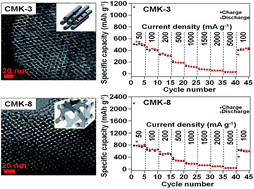
The rate capability of the CMK-3 and CMK-8 electrodes was evaluated to understand their electrochemical performance as the anode materials for lithium-ion batteries. Fig. 8 displays the rate capability of the CMK-3 and CMK-8 electrodes. The CMK-8 electrode exhibits better performance than the CMK-3 electrode with the increase in the current density. At a current density of 50 mA g−1, the CMK-8 electrode possesses a reversible capacity of around 800 mA h g−1 compared to ∼522 mA h g−1 for the CMK-3 electrode. At a comparatively higher C-rate of 1500 mA g−1, the reversible capacity values of 126 mA h g−1 and 73 mA h g−1 were obtained for the CMK-8 and CMK-3 electrodes, respectively, after 30 cycles. At an extremely high C-rate of 5000 mA g−1, the reversible capacity values of CMK-8 and CMK-3 were reduced to 37 and 27 mA h g−1, respectively, after 40 cycles. When the current density was returned to 100 mA g−1 after 40 cycles, the capacity of the CMK-8 electrode was still maintained above 620 mA h g−1, which was better than the capacity value of CMK-3 (420 mA h g−1). The higher reversible capacity of CMK-8 in comparison to CMK-3 can be inferred to the different mesostructures of the materials. Since the textural properties of CMK-3 and CMK-8 are quite similar (surface area, pore volume and pore size), it suggests that the unique 3D cubic mesostructure of CMK-8 with interpenetrating bicontinuous network of pore channels provides a highly opened porous host with an easier access to Li+ ions, thus facilitating the faster Li+ diffusion and electron transfer throughout the pore channels without pore blockage in comparison to the 2D hexagonal cylindrical mesostructure of CMK-3. Scheme 1 also depicts the Li+ ions diffusion in the pore channels of CMK-3 and CMK-8. Consequently, more surface active sites are accessible for Li+ ion adsorption in the bicontinuous cubic structure of CMK-8, which resulted in a higher Li storage capacity and rate performance than the hexagonal structure of CMK-3. In addition, the smaller particle size of CMK-8 in comparison to that of CMK-3 (Fig. S3) reduces the travel path and favors the rapid mass and charge transfer during insertion/extraction of lithium ions. Moreover, the slightly larger pore diameter of CMK-8 relative to CMK-3 is also helpful for the faster movement of Li+ ions, and thus enhances the rate performance.


image file: c5ra05168a-f8.tif
Fig. 8 Rate performance of CMK-3 and CMK-8 electrodes at various current densities.

The cycle performance of the CMK-3 and CMK-8 electrodes is shown in Fig. 9 at a charge–discharge rate of 100 mA g−1. The CMK-3 electrode exhibits the discharge capacities of 964, 407 and 356 mA h g−1 at the 1st, 2nd, and 100th cycles, respectively. Alternatively, the CMK-8 electrode shows the discharge capacities of 1884, 654 and 569 mA h g−1 at the 1st, 2nd, and 100th cycles, respectively. At the 100th cycle, the discharge capacity value of the CMK-8 electrode is almost 37.4% higher than the discharge capacity of the CMK-3 electrode. The higher Li storage capacity observed for the CMK-8 electrode is one of the reasons for its better capacity and cyclability than the CMK-3 electrode. Although both the mesoporous carbon based electrodes demonstrate good capacity values, the ordered 3D cubic mesoporous structure of CMK-8 is more preferable for charge transport than the 2D hexagonal structure of CMK-3. As the ion transport is unidirectional in the 2D hexagonal cylindrical channels of CMK-3, the cubic mesoporous CMK-8 based electrode has better ion transport properties due to the higher degree of pore interconnectivity. It is believed that the unique 3D network of CMK-8 could facilitate ion diffusion throughout the mesoporous channels with much less pore blockage, which makes the CMK-8 based electrode more favorable for charge transfer. Moreover, the 3D interconnected ordered mesopore framework of CMK-8 can accommodate the volume change (expansion/contraction) during the charge–discharge cycling to enhance the structural stability.40 In comparison to CMK-3, CMK-8 exhibits a slightly larger mesopore diameter and pore volume, which allow more Li-ions to be accommodated, and thus are also helpful in improving the specific capacity.


image file: c5ra05168a-f9.tif
Fig. 9 Cycle performance and coulombic efficiency of CMK-3 and CMK-8 mesoporous electrodes at a current density of 100 mA g−1.

The structural stability of the CMK-3 and CMK-8 electrode materials is analyzed by the SEM measurements after 100 charge–discharge cycles. The morphological changes of the electrode materials that had occurred during cycling are shown in Fig. S4 (ESI). It is observed that the CMK-3 electrode possesses a slightly layered type structure with tiny particles on the surface. On the other hand, the structure of the CMK-8 electrode is more or less uniform with very small particles on the surface. As there are no cracks observed on the surfaces, it suggests that the OMCs have efficiently managed the volume expansion and contraction during the lithium insertion and extraction processes.

Coulombic efficiency can be used to determine the impact of electrolytes, impurities, electrode materials, etc., on the cycle life of a battery. Although some fluctuations observed in the coulombic efficiency values for initial cycles of the CMK-3 electrode, the coulombic efficiency values become stable and maintain around 96–99% from 23 to 100 cycles. On the other hand, the coulombic efficiency of CMK-8 is almost stable excluding a few initial cycles, and maintained around 97–99% efficiency from 10 to 100 cycles. The observed irreversible capacity loss is caused by the formation of SEI film on the surface of the mesoporous electrode due to the decomposition of electrolyte. The formation of SEI layer consumes a part of the electrode capacity corresponding to an irreversible capacity loss. The SEI layer reduces the charge transfer in the electrode and slower the diffusion rate of Li+ ions. It is also observed that the first and second cycles coulombic efficiency values of CMK-3 (37.3% and 90.9%, respectively) are higher than the CMK-8 (30.9% and 84%, respectively), although the latter possesses higher capacity. This may be attributed to the 3D cubic mesostructure of the CMK-8, where the electrolyte can diffuse easily and quickly, and decomposed to form the SEI layer. On the other hand, the diffusion of the electrolyte in 2D hexagonal mesostructure of CMK-3 is slower, and hence the formation of SEI layer takes a comparatively longer time, which help to achieve relatively higher coulombic efficiency values than CMK-8 in the initial two cycles. As the coulombic efficiency is over 95% after some initial cycles, it is suggested that the SEI layer becomes steady for subsequent lithium insertion and extraction processes. It should be noted that the charge–discharge performance of CMK-3 reported in this study somehow varies to some extents with the results reported in the literature, mainly due to different preparation techniques and the fabrication method of the battery cells. Nevertheless, given to the better overall electrochemical performance of CMK-8, we believe that CMK-8 is an ideal carbon matrix, in comparison to CMK-3, to be used as the anode material in LIBs.

Conclusions

Two types of ordered mesoporous carbons CMK-3 and CMK-8 with different mesostructures were synthesized by the nanocasting method and used as anode materials for lithium ion batteries. A comparative study was carried out to evaluate the effects of morphology and structure of the CMK-3 and CMK-8 electrodes on their electrochemical performances in Li-ion batteries. The 3D cubic ordered mesostructure of CMK-8 allowed the mass transport and charge transfer easier at the time of charge–discharge cycling than the 2D hexagonal ordered mesostructure of CMK-3. In comparison to the CMK-3 electrode, the CMK-8 electrode possesses a higher reversible capacity, better cycling stability and rate performance. The initial capacities of 1884 and 964 mA h g−1 were obtained for the CMK-8 and CMK-3 electrodes, respectively, which finally delivered reversible capacities of 569 and 356 mA h g−1 after 100 cycles at the current density of 100 mA g−1. The unique structural advantages of CMK-8, in comparison to CMK-3, could be extended for the fabrication of the electrode materials composed of metal oxide decorated CMK-8 composites to achieve further enhancement of their electrochemical performances in lithium-ion batteries.

Acknowledgements

The financial support of this work by the Ministry of Science and Technology, Taiwan is gratefully acknowledged. The authors would also like to thank Prof. C. S. Chen from Chang Gung University for providing Raman measurements.

Notes and references

  1. J. B. Goodenough and K.-S. Park, J. Am. Chem. Soc., 2013, 135, 1167 CrossRef CAS PubMed .
  2. Y. Xing, Y. Wang, C. Zhou, S. Zhang and B. Fang, ACS Appl. Mater. Interfaces, 2014, 6, 2561 CAS .
  3. J. M. Tarascon and M. Armand, Nature, 2001, 41, 359 CrossRef PubMed .
  4. V. Etacheri, R. Marom, R. Elazari, G. Salitra and D. Aurbach, Energy Environ. Sci., 2011, 4, 3243 CAS .
  5. L. Lu, X. Han, J. Li, J. Hua and M. Ouyang, J. Power Sources, 2013, 226, 272 CrossRef CAS PubMed .
  6. S. Flandrois and B. Simon, Carbon, 1999, 37, 165 CrossRef CAS .
  7. Z. H. Yi, Y. G. Liang, X. F. Lei, C. W. Wang and J. T. Sun, Mater. Lett., 2007, 61, 4199 CrossRef CAS PubMed .
  8. Y. Chen, Z. Lu, L. Zhou, Y.-W. Mai and H. Huang, Energy Environ. Sci., 2012, 5, 7898 CAS .
  9. Y. Chen, Z. Lu, L. Zhou, Y.-W. Mai and H. Huang, Nanoscale, 2012, 4, 6800 RSC .
  10. Y. Chen, X. Li, X. Zhou, H. Yao, H. Huang, Y.-W. Mai and L. Zhou, Energy Environ. Sci., 2014, 7, 2689 CAS .
  11. Y. Chen, C. Liu, X. Sun, H. Ye, C. Cheung and L. Zhou, J. Power Sources, 2015, 275, 26 CrossRef CAS PubMed .
  12. E. Frackowiak and F. Béguin, Carbon, 2002, 40, 1775 CrossRef CAS .
  13. L. Ji and X. Zhang, Electrochem. Commun., 2009, 11, 684 CrossRef CAS PubMed .
  14. Z. S. Wu, W. Ren, L. Xu, F. Li and H. M. Cheng, ACS Nano, 2011, 5, 5463 CrossRef CAS PubMed .
  15. K. T. Lee, J. C. Lytle, N. S. Ergang, S. M. Oh and A. Stein, Adv. Funct. Mater., 2005, 15, 547 CrossRef CAS PubMed .
  16. A. Chen, C. Li, R. Tang, L. Yin and Y. Qi, Phys. Chem. Chem. Phys., 2013, 15, 13601 RSC .
  17. J. Ma, D. Xiang, Z. Li, Q. Li, X. Wang and L. Yin, CrystEngComm, 2013, 15, 6800 RSC .
  18. H. Zhang, H. Tao, Y. Jiang, Z. Jiao, M. Wu and B. Zhao, J. Power Sources, 2010, 195, 2950 CrossRef CAS PubMed .
  19. H. Qiao, J. Li, J. Fu, D. Kumar, Q. Wei, Y. Cai and F. Huang, ACS Appl. Mater. Interfaces, 2011, 3, 3704 CAS .
  20. Z. Li, X. Wang, C. Wang and L. Yin, RSC Adv., 2013, 3, 17097 RSC .
  21. J.-W. Lang, X.-B. Yan, X.-Y. Yuan, J. Yang and Q.-J. Xue, J. Power Sources, 2011, 196, 10472 CrossRef CAS PubMed .
  22. S. Tao, W. Yue, M. Zhong, Z. Chen and Y. Ren, ACS Appl. Mater. Interfaces, 2014, 6, 6332 CAS .
  23. J. Park, G.-P. Kim, H. N. Umh, I. Nam, S. Park, Y. Kim and J. Yi, J. Nanopart. Res., 2013, 15, 1943 CrossRef .
  24. F. D. Lupo, C. Gerbaldi, G. Meligrana, S. Bodoardo and N. Penazzi, Int. J. Electrochem. Sci., 2011, 6, 3580 Search PubMed .
  25. M. Yang and Q. Gao, Microporous Mesoporous Mater., 2011, 143, 230 CrossRef CAS PubMed .
  26. M.-S. Kim, D. Bhattacharjya, B. Fang, D.-S. Yang, T.-S. Bae and J.-S. Yu, Langmuir, 2013, 29, 6754 CrossRef CAS PubMed .
  27. H. S. Zhou, S. M. Zhu, M. Hibino, I. Honma and M. Ichihara, Adv. Mater., 2003, 15, 2107 CrossRef CAS PubMed .
  28. R. Guo, W. Yue, Y. An, Y. Ren and X. Yan, Electrochim. Acta, 2014, 135, 161 CrossRef CAS PubMed .
  29. D. Y. Zhao, J. L. Feng, Q. S. Huo, N. Melosh, G. H. Fredrickson, B. F. Chmelka and G. D. Stucky, Science, 1998, 279, 548 CrossRef CAS .
  30. F. Kleitz, S. H. Choi and R. Ryoo, Chem. Commun., 2003, 17, 2136 RSC .
  31. R. Ryoo, S. H. Joo, S. Jun, T. Tsubakiyama and O. Terasaki, Stud. Surf. Sci. Catal., 2001, 135, 150 CrossRef .
  32. S. Jun, S. H. Joo, R. Ryoo, M. Kruk, M. Jaroniec, Z. Liu, T. Ohsuna and O. Terasaki, J. Am. Chem. Soc., 2000, 122, 10712 CrossRef CAS .
  33. Y. Chen, X. Li, K. Park, J. Song, J. Hong, L. Zhou, Y.-W. Mai, H. Huang and J. B. Goodenough, J. Am. Chem. Soc., 2013, 135, 16280 CrossRef CAS PubMed .
  34. K. N. Kudin, B. Ozbas, H. C. Schniepp, R. K. Prudhomme, I. A. Aksay and R. Car, Nano Lett., 2008, 8, 36 CrossRef CAS PubMed .
  35. G. Wang, W. Xing and S. Zhuo, Electrochim. Acta, 2013, 92, 269 CrossRef CAS PubMed .
  36. B. Fang, M.-S. Kim, J. H. Kim, S. Lim and J.-S. Yu, J. Mater. Chem., 2010, 20, 10253 RSC .
  37. S. Yang, X. Feng, L. Zhi, Q. Cao, J. Maier and K. Müllen, Adv. Mater., 2010, 22, 838 CrossRef CAS PubMed .
  38. J. Jamnik and J. Maier, J. Electrochem. Soc., 1999, 146, 4183 CrossRef CAS PubMed .
  39. C. S. Wang, A. J. Appleby and F. E. Little, Electrochim. Acta, 2001, 46, 1793 CrossRef CAS .
  40. M.-H. Park, K. Kim, J. Kim and J. Cho, Adv. Mater., 2010, 22, 415 CrossRef CAS PubMed .

Footnote

Electronic supplementary information (ESI) available: Small angle XRD and nitrogen adsorption–desorption isotherms of SBA-15 and KIT-6, dynamic light scattering measurements of CMK-3 and CMK-8, and SEM images of CMK-3 and CMK-8 samples after 100 cycles. See DOI: 10.1039/c5ra05168a

This journal is © The Royal Society of Chemistry 2015
Click here to see how this site uses Cookies. View our privacy policy here.