A review on recent developments of anion exchange membranes for fuel cells and redox flow batteries

Sandip Maurya , Sung-Hee Shin , Yekyung Kim and Seung-Hyeon Moon *
School of Environmental Science and Engineering, Gwangju Institute of Science and Technology (GIST), 123Cheomdan-gwagiro, Buk-gu, Gwangju 500-712, Republic of Korea. E-mail: shmoon@gist.ac.kr; Fax: +82-62-715-2434; Tel: +82-62-715-2435

Received 18th March 2015 , Accepted 13th April 2015

First published on 13th April 2015


Abstract

Cation exchange membranes (CEMs) have attracted tremendous attention in electrochemical energy conversion and storage systems owing to their high proton conductivity and chemical stability. However, applications of CEMs suffer from a number of disadvantages such as requirement of costly platinum catalyst, and high crossover of fuels or positively charged redox species due to the electro-osmotic drag. Anion exchange membranes (AEMs) have shown promising characteristics to overcome some of the problems associated with CEMs; the advantages of AEMs being selective transport anionic charge carriers, lower crossover of cationic redox couples, and facile reaction kinetics in energy conversion processes. These unique properties of AEMs result mainly from the density and distribution of positively charged functional groups, along with a macromolecular polymer backbone. As a result, there has been an increasing demand for the development of AEMs with better selectivity, higher chemical stability and conductivity, and a lot of work has been carried out in this area. The aim of this review is to discuss developments in the synthesis and applications of AEMs in the field of electrochemical energy conversion and storage, on which many researchers have been working in recent years.
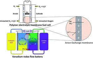

image file: c5ra04741b-p1.tif

Sandip Maurya

Sandip Maurya received his bachelor degree in chemistry from Veer Narmad South Gujrat University of Surat, India in 2007. He completed his master of science degree in applied chemistry from The Maharaja Sayajirao University of Baroda, India in 2009. After graduation he worked for Central Salt and Marine Chemicals Research Institute (CSIR-CSMCRI) in India on hollow fiber membranes for waste water reclamation. At present, he is PhD candidate at Gwangju Institute of Science and Technology (GIST, Korea). His current research focuses on stable anion exchange membranes for energy conversion and storage systems.

image file: c5ra04741b-p2.tif

Sung-Hee Shin

Sung-Hee Shin accomplished her bachelor degree in environmental science and engineering from Chosun University of Korea in 2006. She received her master of science degree in environmental science and engineering at GIST, Korea in 2011. She is currently PhD candidate at GIST. She has been studying fundamental electrochemical-methods for electrochemistry oriented sensors and energy conversion/storage systems. Her current research interests are multifunctional polymer electrolyte membranes for non-aqueous/aqueous redox flow batteries, highly stable lithium ion battery separators including ion transport phenomena through the membranes.

image file: c5ra04741b-p3.tif

Yekyung Kim

Yekyung Kim finished her bachelor degree in environmental science and engineering from Myongji University of Korea in 2007. She also completed her master of science degree in environmental science and engineering at Myongji University in 2010. She is currently PhD candidate at GIST. She has been studying on one-step fabrication of composite membrane, especially anti-biofouling membrane, and membrane water treatment systems. Her current research interests are fabrication of porous ion exchange membranes for energy conversion/storage systems, electrochemical analysis of the membranes, and electron transfer mechanism of a microbial fuel cell.

image file: c5ra04741b-p4.tif

Seung-Hyeon Moon

Professor Seung-Hyeon Moon received his Master and Doctorate degree in Chemical Engineering from Seoul National University of Korea in 1982 and Illinois Institute of Technology, USA in 1990, respectively. Since then, he has been working on synthesis, characterization, and process application of electromembranes. In GIST, he continued the membrane studies for cleaner technologies and industrial wastewater treatment. He led the National Research Laboratory (NRL) on electromembranes processes for cleaner environments and Basic Atomic Energy Research Institute (BAERI) on water chemistry in nuclear power plants. Since 2014, he has been a Director at Energy and Environment Technology Division, National Research Foundation of Korea (NRF). He published over 200 journal articles and holds 30 patents in this research area. He is particularly interested in the development of charged membranes for advanced water treatment and energy conversion systems based on electrochemistry.


1. Introduction

The irreversible environmental effects of greenhouse gas emissions, the growing demand for sustainable energy sources, and the need for energy security have forced the migration from hydrocarbon based fossil fuels to renewable and environmentally friendly energy sources.1 Also, an increased awareness of the environmental issues along with a potential energy shortage has led to accelerated research efforts in energy conversion and storage. Distributed power generation systems based on fuel cells are expected to be an important power source in the future due to their advantages, such as attractive efficiency, low carbon emission, and flexible operations.2 However, their inherent characteristics such as a long start-up time and poor response to immediate power demands are major obstacles for the commercialization of such systems. Therefore, hybrid distributed power systems based on fuel cells and batteries are introduced, in order to best utilize the individual characteristics of each device.3,4 Most electrochemical conversion and storage systems such as fuel cells and redox flow batteries are dependent on ion exchange membranes (IEMs).5–7 These devices can work only if the IEM separates the anode and the cathode chambers and mediate the conducting ions (e.g., protons and hydroxide ions) for the electrochemical reactions in the system. Apart from good conducting properties, some other requirements such as crossover and chemical stability are major concerns in the development of IEMs.8,9

1.1. Polymer electrolyte membrane fuel cells (PEMFC)

While fuel cells were invented in 1839 by Sir William Grove, their first practical use was reported only in the 1950s in the NASA Apollo space program.10 Over the past two decades, fuel cell research has gained pace due to the continual and noteworthy efforts to develop fuel cell materials and systems for high-energy portable power sources. As a result, several improvements have been made, to enable the commercialization of fuel cells. A schematic representation of the reactions in a fuel cell is shown in Fig. 1 and the classifications and characteristics of various fuel cells are presented along with their operating temperatures in Table 1.
image file: c5ra04741b-f1.tif
Fig. 1 Schematic representation of fuel cell reactions with CEM (left) and AEM (right).
Table 1 Classification of fuel cells based on types of electrolytes
Type Electrolyte Operating temperature (°C) Fuel
Alkaline fuel cell (AFC) 35–45% potassium hydroxide (KOH) 60–90 °C Pure hydrogen
Polymer electrolyte membrane fuel cell (PEMFC) Proton exchange membrane and anion exchange membrane 60–90 °C Pure hydrogen, methanol, ethanol
Phosphoric acid fuel cell (PAFC) 100% phosphoric acid 180–220 °C Hydrogen
Molten carbonate fuel cell (MCFC) Molten carbonate salts (62% LiO2CO3, 38% K2CO3) 550–650 °C Hydrogen, hydrocarbons, carbon monoxide
Solid oxide fuel cell (SOFC) Stabilized zirconia and yttria 800–1000 °C Hydrogen, hydrocarbon, carbon monoxide


Low temperature PEMFCs offer power densities that are an order of magnitude higher than those for the other types of fuel cells. In addition, they have quick start-up, lower cost, longer life, and wider applications compared to other types of fuel cells.11 The PEMFCs can be further divided into two categories based on the type of polymer electrolyte membranes (PEMs) used, namely acidic PEMs (proton conducting cation exchange membranes (CEMs)) and alkaline PEMs (hydroxide conducting anion exchange membranes (AEMs)). Acid based PEMFCs have been used commercially in some stationary and mobile applications such as power backup in domestic areas.12 Precious metal catalysts are necessary to facilitate the electrochemical reactions at acidic pH values and to avoid catalyst corrosion.13 Therefore, these PEMFCs mostly use pure hydrogen and methanol as fuels and a humidified supply of oxygen or air as oxidizers, within the allowed temperature range. The fuels have to be very pure in order to prevent catalyst poisoning and ensure sustained fuel cell performance. Significant crossover wastes fuel and causes performance losses at the cathode, owing to the consumption of oxygen and catalyst poisoning, respectively.14

When AEMs are used, precious metal catalysts are no longer needed and can be replaced with cheaper transition metal catalysts, which can promote the facile oxidation of hydrogen or alcohol at the anode under alkaline conditions.15,16 Moreover, the use of AEMs restricts the crossover of alcohol from the anode, which is typically quite fast in the case of CEMs as a result of the opposite migration of hydroxide ions from the cathode to the anode.17 However, AEMs lag far behind in terms of chemical stability under alkaline and oxidative conditions, ionic conductivity, and the availability of suitable ionomers.8,18,19 The poor ionic conductivity of AEMs is ascribed to the transport of comparatively bulkier anions, namely the hydroxide ion.20

1.2. Redox flow batteries

The redox flow battery (RFB) is an important electrochemical energy storage device, which was realized in the 1970s.21 The RFB has an IEM separating the positive and the negative electrolytes. During the charge/discharge cycles, the redox couples undergo electrochemical reduction and oxidation reactions. Simultaneously, the IEM allows the transport of charge carriers to maintain electroneutrality (Fig. 2).22,23 Several redox couples including Zn–Br, polysulfide–bromide, Fe–chrome, and VO2+/V3+ have been investigated (Table 2). Among the various RFBs, vanadium redox flow batteries (VRFBs) have attracted much attention due to the presence of the same metal cation in the catholyte and the anolyte solutions.5 Therefore, the crossover of the vanadium ions through the membrane is a reversible regeneration process, which provides a long life to the electrolyte solution. Despite the several advantages of the VRFBs such as long life, simple redox reactions, and independence from energy and power ratios, the application of this technology continues to be limited. A related disadvantage is the reliability issue that arises from the crossover of the active species through the IEM, which requires the periodic regeneration of the electrolytes in VRFBs.24 CEMs possess high permeability to vanadium ions, since the membranes are intrinsically permeable to cations along with the charge carrier protons.25 Hence, VRFBs assembled with CEMs show lower coulombic efficiency.
image file: c5ra04741b-f2.tif
Fig. 2 Schematic and principle of VRFB.
Table 2 A comparison between various RFB chemistries
Name Half-reactions Eo (V) Disadvantages
Zinc–bromine Anode Zn ↔ Zn2+ + 2e 1.85 Corrosion, crossover and short cycle life
Cathode 3Br ↔ Br3 + 2e
Polysulfide–bromine Anode 2S22− ↔ S42− + 2e 1.36 Corrosion, crossover and sulfur precipitation
Cathode 3Br ↔ Br3 + 2e
Iron–chrome Anode Cr2+ ↔ Cr3+ + e 1.18 Crossover and low cell potential
Cathode Fe2+ ↔ Fe3+ + e
VRFB Anode V2+ ↔ V3+ + e 1.26 Low cell potential
Cathode VO2+ + H2O ↔ VO2+ + 2H+ + e


There have been few reports evaluating the AEMs used in VRFBs.26–30 AEMs contain fixed positively charged groups that can repulse the positively charged vanadium ions (a phenomenon known as Donnan exclusion), resulting in significantly low vanadium ions crossover. The sulfate ion predominantly acts as a charge carrier and the protons contribute to minor charge transfer.31 Unlike the perfluorinated CEMs such as the Nafion membranes, AEMs degrade in strong oxidizing VO2+ solutions (the membrane has to be durable in the oxidizing and reducing solutions) formed during the continuous charge/discharge cycles.32 Unfortunately, there is nearly no systemic membrane development for RFB applications. The available membranes have been tested in single cells for efficiency, active species crossover, and in situ degradation at the catholyte.

2. Anion exchange membranes

AEMs are viable alternatives to CEMs and are currently gaining renewed attention. Recently, some reviews have been published on AEMs for alkaline fuel cells.6,10,33–36 While Merle et al.10 included polymeric materials that could potentially be used in alkaline fuel cells, and their properties, Couture et al.6 summarized the synthesis of anion exchange polymeric materials containing ammonium groups. They also focused on approaches for the chemical modification of conventional polymers such as hydrogenated aliphatic and aromatic polymers. Varcoe et al. emphasized the crucial concepts, limitations and challenges associated with AEMs in various electrochemical conversion and storage systems including fuel cells and RFBs.7 However, the performance of fuel cells based on the types of functional groups and the nature of the polymer backbones is yet to be compared and would provide a better understanding of the energy conversion systems. To the best of author's knowledge, a few reviews on AEMs for energy storage applications such as in RFBs and metal-ion batteries are available, although there is a constant increase in the number of research articles published on AEMs. This is obvious from Fig. 3, which shows the number of publications containing the terms “anion exchange membrane”, “fuel cell”, or “battery”, displayed in a Scopus® reference search over the last 15 years (the data point for the 2014 publication year includes data until April, 2014).
image file: c5ra04741b-f3.tif
Fig. 3 Number of research articles related to AEMs published for fuel cells or RFBs during last fifteen years.

2.1. Polymers for AEMs

In recent years, intensive efforts have been made to develop AEMs for energy applications. The membranes are required not only to conduct anions, but also to serve as a barrier for the fuel or charged electrolytes. So far, very few types of polymers have been utilized as AEMs in PEMFCs. The AEMs are most often based on polystyrene (PSt) crosslinked with divinylbenzene (DVB) with the quaternary ammonium group linked to a benzylic methylene group. Early studies involved the use of these polymers, owing to their low cost and easy synthesis. However, they possess several drawbacks such as low chemical and thermal stability and limited processability. In view of this, many other polymers such as polyarylene sulfone, polyphenylene oxide (PPO), polyether imide, polyether ether ketone (PEEK), polybenzimidazole, copolymers from vinyl monomers, and grafted fluoropolymers, have been developed as promising alternatives and have good chemical and thermal stability, mechanical processability, and low cost. In addition, these polymers can be easily functionalized with cationic functional groups by chloromethylation–quaternization. The key properties and fuel cell performances of AEMs prepared from various polymers are presented in Table 3.
Table 3 Typical characteristics of AEMs described in this review for fuel cellsa
Membrane type IEC (meq. g−1) Ionic conductivity (mS cm−1) Chemical stability PEMFC performance Type
Condition Endurance Current density (mA cm−2) Power density (mW cm−2) Temp. (°C)
a σ = conductivity loss, ΔIEC = IEC loss, Δw = weight loss. PVB = polyvinylbenzyl, PECH = polyepichlorhydrin, PAEK = polyarylene ether ketone, poly(MM-co-BA-co-VBC) = poly(methyl methacrylate-co-butyl acrylate-co-vinylbenzyl chloride), AmimCl = 1-allyl-3-methylimidazolium chloride, AAPTMS-GPTAC-TEOS = 3-(2-aminoethylamino)propyltrimethoxysilane-glycidoxypropyltrimethylammonium chloride-tetraethoxysilane. * ambient temperature or not specified.
(1) Fluorinated polymers
ETFE-PVB-trimethyl ammonium37 1.03 27 (20 °C) 94 50 °C H2/O2
FEP-PVB-trimethyl ammonium38 0.71–0.96 10–20* Water, 100 °C 2856 h, ΔIEC = 18%
ETFE/PVB-DABCO-trimethyl ammonium39 1.67–2.11 26–39 (30 °C) 2–10 M KOH, 60 °C 120 h, σ = 0 69 48 40 H2/O2
PTFE/PECH-imidazolium40 1.31–1.64 14–18 (30 °C) 1 M KOH, 60 °C 15 day, σ = 0 23 58 50 H2/O2
[thin space (1/6-em)]
(2) Hydrocarbon based polymers
(2a) Vinyl polymers
PE/PSt-co-DVB-trimethylammonium41 0.80–0.96 25.0–35.0* Fenton solution, 80 °C 12 h, ΔIEC = 0.69–0.75%
PSt-b-PE-ran-PVB-b-PSt-trimethylammonium42 0.3 9.37 (80 °C) Fenton solution, 80 °C 120 h, σ = 35%
[thin space (1/6-em)]
(2b) Poly(ether sulfone)s
PS-imidazolium43 1.39–2.46 16.1–20.7 (20 °C) 3 M NaOH, 60 °C 24 h, σ = 23.3% 110 16 60 H2/O2
PS-crosslinked-trimethyl ammonium44   <11     70 30.1 60 H2/O2
PES-imidazolium45 1.45 0.3 (20 °C) 2 M NaOH, 60 °C 168 h, σ = 13.3%
[thin space (1/6-em)]
(2c) Polyethers                
PECH-co-allyl glycidyl ether-DABCO46 1.3 2.5 (25 °C)
PPO-PVB-trimethyl ammonium47 0.5–1.55 4–31 (25 °C) 2 M KOH, 80 °C 192 h, ΔIEC = 40%
PPO-guanidinium48 0.37–2.69 11–71 (25 °C) 1 M KOH, 25 °C 192 h, σ = 0 34 16 50 H2/O2
PPO-crosslinked-DABCO49 0.6–1.1 0.9–5.4* 1 M KOH, 90 °C 240 h, ΔIEC = 0, σ = 0 450 132 80 DMFC
PPO-benzimidazolium50 0.63–2.21 10–37 (25 °C) 2 M KOH, 25 °C 168 h, ΔIEC = 18%, σ = 35% 40 13 50 H2/O2
[thin space (1/6-em)]
(2d) Polyketones
PPEK-imidazolium51 1.52–2.63 28 (30 °C) 2 M KOH, 60 °C 48 h, σ = 0        
PPEK-trimethyl ammonium52   11.4 (80 °C)     0.037 0.0077 70 DMFC
PAEK-trimethyl ammonium53 1.32–1.46 12–23 (20 °C) 4 M KOH* 168 h, ΔIEC = 0, σ = 0
PEEK-trimethyl ammonium54 0.43–1.35 0.5–12 (30 °C)
PEEK-DABCO55 0.86–1.69 18.4–47.8 (25 °C) 2 M KOH, 60 °C 120 h, σ = 40–60%
PEEK-imidazolium56 1.56–2.24 15–52 (20 °C) 75 31 50 DMFC
[thin space (1/6-em)]
(2e) Acrylates and methacrylates
Poly(MM-co-BA-co-VBC)-trimethyl ammonium57 0.66–1.25 2.9–5.3 80 35 60 H2/O2
Poly(MMA-co-VBC-co-EA)-trimethyl ammonium58 0.06–0.13 8.42–14.79 (30 °C) 1–6 M KOH, 60 °C 120 h, σ = 5–55%
Poly(AmimCl-MMA)-imidazolium59 0.154–0.217 15.4–33.3 (30 °C) 6 M KOH, 60 °C 120 h, σ = 8.4–55.8%
[thin space (1/6-em)]
(2f) Polyolefins
PE-trimethyl ammonium60 1.29–1.50 40–48 (20 °C)
[thin space (1/6-em)]
(3) Condensation polymers
(3a) Polybenzimidazole
Quaternized-N-ethyl polybenzimidazole61   22 (25 °C) 50 11 13 DEFC
Polybenzimidazole-imidazolium62 1.49 5.54 (30 °C) 1 M KOH, 30 °C 96 h, σ = 82%
[thin space (1/6-em)]
(3b) Polyimides
Poly(ether-imide)-trimethyl ammonium63 0.186 0.57 (25 °C) 1–9 M KOH, 25–95 °C 24 h, stable
[thin space (1/6-em)]
(4) Other type of membranes
(4a) Composite membranes
Pore-filled PE/PVB-trimethyl ammonium salt64 1.33–1.67 Up to 40 (20 °C) 5 M NaOH, 50 °C 1500 h, stable
Pore-filled PE/PVB-trialkyl ammonium20 1.09–1.22 29.6–38.1 (25 °C) 1 M NaOH, 60 °C 75 h, σ = 0% 200 90 60 H2/O2
PVA-AAPTMS-GPTAC-TEOS (PVA-silica-trimethyl ammonium)65 1.21–1.76 34.8–75.7 (30 °C) Fenton solution, 80 °C 1 h, Δw = 8–12%
PPO/silica-triethyl ammonium66 2.0–2.3 0.8–11 (30 °C) 80 30 50 H2/O2
Quaternized chitosan-silica-trimethyl ammonium67 0.93–1.82 Up to 18.9 (80 °C) 1 M KOH, 80 °C 120 h, σ = 12.75–45.50%
[thin space (1/6-em)]
(4b) Alkali doped electrolytes
Polybenzimidazole–KOH68   18.4* 2 M KOH Stable 31 90 DMFC
Polybenzimidazole–KOH69   Up to 100 (30 °C) 620 50 H2/O2
Polyvinyl alcohol-KOH70   0.275–0.473* 10 M KOH, 120 °C Stable
Polyethylene oxide–KOH71   0.5–1*


2.2. AEM fabrication methods

The commercial manufacturing procedures for AEMs include the paste method, block polymerization, and the latex method.72 However, the interest in synthesizing membranes for various applications has led to the development of several other routes for membrane synthesis such as (a) copolymerization and direct solution casting, (b) sol–gel technique, (c) grafting and plasma polymerization, (d) pore-filling method, and (e) supported composite AEMs. It may be noted that the preparation of AEMs involves the carcinogenic reagent chloromethyl methyl ether, which is potentially harmful to human health. Therefore, recent research has also focused on relatively green and environmentally friendly synthesis methods for AEMs, wherein, several efforts have been made to avoid the use of chloromethyl methyl ether. Such methods include the copolymerization of vinylbenzyl chloride (VBC) with DVB, the grafting of VBC or vinylpyridine onto polymer films, and the copolymerization of epoxy acrylates such as glycidyl methacrylate (GMA).
2.2.1. AEMs prepared by the polymerization of monomers. In this section, we discuss the AEMs prepared by the polymerization of monomers, where at least one of the monomers contains a functional moiety that can be converted into cations. A typical example of such an AEM is the copolymer consisting of VBC or 4-vinylpyridine and divinylbenzene, which has the functional group shown in Fig. 4. Moreover, inert polymers are added to the monomer mixture to maintain the mechanical strength of the resulting membrane.73 The role of the inert polymer is not limited to improving the dimensional strength of the resulting membrane, but its addition provides an optimum viscosity to the casting solution.74 As a result, thin films can be casted directly on glass plates, and are further quaternized either by a tertiary amine or an alkyl halide. Recently, a solvent free synthesis strategy was introduced by Wu et al.,47 where the use of environmentally hazardous solvents was avoided. The process began with the dissolution of the bromomethylated poly(2,6-dimethyl-1,4-phenylene oxide) (BPPO) polymer in the monomers, followed by in situ polymerization and quaternization using trimethylamine. More recently, a simple and efficient synthesis route for AEMs was reported where the chloromethylation step was avoided by using 4-vinyl pyridine.27 Further, the simultaneous polymerization and quaternization of 4-vinylpyridine excluded a separate step for quaternization, which requires trimethylamine.
image file: c5ra04741b-f4.tif
Fig. 4 A typical reaction scheme for the preparation of chloromethylstyrene-divinylbenzene based AEMs.

Monomers without functional groups can also be polymerized as a block, which can be further sliced into thin films. For example, styrene with DVB is polymerized into a block in the presence of benzoyl peroxide, which acts as a thermal initiator.72 The resultant membranes are subjected to chloromethylation and quaternization, for imparting anion exchange functionality. However, the addition of vinylpyridine instead of styrene, yields an AEM directly when quaternized with an alkyl halide.75 These membranes exhibit excellent electrochemical properties in terms of area resistance, which is attributed to their homogeneous structure. Moreover, crosslinked PSt polymer matrices provide good mechanical strength. However, slicing a large block of polymer requires high precision instruments. Therefore, this method is not viable for laboratory scale membrane preparation.72

2.2.2. AEMs prepared from conventional polymers by the solution casting method. In order to use the energy conversion and storage systems under strongly alkaline and oxidative conditions and at high temperatures, stable Nafion and Dow membranes have been developed and successfully employed as PEMs (Fig. 5). However, it was observed that none of the commercial AEMs showed sufficient chemical stability under such aggressive conditions.
image file: c5ra04741b-f5.tif
Fig. 5 Chemical structures of (A) Nafion and (B) Dow perfluorinated membranes.

Therefore, developing new types of AEMs that exhibit better stability in harsh chemical environments and possess good electrochemical stability as well has been a challenge. Engineering plastics such as polysulfone (PS), polyethersulfone (PES), poly ether ketone (PEK), and PEEK have high glass transition temperatures, excellent chemical and thermal stability, and have been widely used as a base polymer for water purification membranes.76,77

The solution casting method is generally applied to soluble polymers, their blends, or copolymers. It primarily consists of four steps, namely the dissolution of the polymer, functional group introduction by chloromethylation, film casting, and quaternization (Fig. 6).


image file: c5ra04741b-f6.tif
Fig. 6 Schematic representation of the synthesis of PS based AEM by chloromethylation and quaternization.

Hwang et al.78 prepared an AEM by synthesizing a block copolymer of PS and polyphenylenesulfidesulfone, followed by conventional chloromethylation and quaternization, using the solution casting method. However, the area resistance was reported to be 3.30 Ω cm2, which is too high for applications in fuel cells. Quaternized poly(phthalazinone ether sulfone ketone) was synthesized by conducting a chloromethylation reaction in 98% sulfuric acid and the less toxic than proven carcinogen, chloromethyl octyl ether.79 The resultant membrane showed good chemical and mechanical stability in VRFBs.80 Several other alternatives have been proposed to minimize the hazards involved in the synthesis of AEMs, such as the polymerization of halomethyl-substituted monomers (e.g., VBC). However, the monomers are relatively expensive. Therefore, the use of halomethylated monomers increases the manufacturing costs of the membranes.

In Table 4, the different conditions for chloromethylation are summarized. Among the various chloromethylation reactions listed, the method in which only paraformaldehyde, hydrochloric acid, and zinc chloride are used, is the least toxic process from the point of view of carcinogenic properties.81 It may be noted that control over the chloromethylation reaction is difficult to achieve, which causes high swelling upon quaternization. Therefore, bromination and bromomethylation are adopted for the synthesis of AEMs, and the use of carcinogenic reagents is avoided in these methods.

Table 4 The reaction parameters for the chloromethylation of various polymers
Chloromethylation agent Solvent Temperature Polymer
Chloromethyl ether + ZnCl2 (ref. 82 and 83) Chloroform, tetrachloroethane 70–75 °C PS, poly(ether-imide), poly(arylene ether sulfone)
Chloromethyl octyl ether80 98% H2SO4 RT Poly(phthalazinone ether sulfone ketone)
Paraformaldehyde + HCl + ZnCl2 (ref. 81 and 84) Chloroform 0 °C PEK, PSt-(ethylene butylene)-PSt
Paraformaldehyde + SnCl4 + chlorotrimethylsilane85,86 Chloroform 55 °C PS
1,4-Bis-(chloromethoxy)-butane87 98% H2SO4 0 °C PES, PEEK
N-Bromosuccinimide + benzoyl peroxide41,88 Tetrachloroethane 85 °C PS, PPO, poly(p-methylstyrene)
Bromine + chlorobenzene89 Chlorobenzene RT PPO


Methyl groups containing PS, polyphenylene oxide, or other aromatic polymers have been brominated using N-bromosuccinimide (NBS) in chlorinated solvents such as tetrachloroethane or dichloroethane. Bromination is considered to be a safe and well-regulated process, where the degree of bromination can be controlled by the amount of NBS and methylated monomers.41,90 Subsequently, the bromomethylated polymers can be casted as thin films, followed by quaternization.

2.2.3. AEMs prepared from conventional polymers by the grafting method. In principle, graft copolymerization is a process in which the side chain grafts are covalently attached to the main chain of the polymer backbone, to form a branched copolymer. A graft copolymer can be represented by Fig. 7, where P and G indicate the main polymer chain and the graft polymer, respectively.
image file: c5ra04741b-f7.tif
Fig. 7 Schematic representation of the structure of graft polymer.

The extent of polymerization is termed as the degree of grafting and can be estimated from the increase in the polymer weight. Radiation-induced graft copolymerization has the potential to simplify and reduce the cost of the process without leaving detrimental residue, and is able to initiate polymerization in a wide range of polymers that are incompatible with monomers.91 For membrane applications where a thin film is required, graft copolymers can be easily formed on thin films that already have the physical shape of the membrane.92

Significant efforts have been made to develop AEMs by the radiation grafting of vinyl monomers such as VBC, vinyl pyridines, and glycidyl methacrylates onto different polymer films. Non-fluorinated polymer substrates such as polyethylene (PE) and polypropylene (PP),93 partially fluorinated polymers such as polyvinylidene fluoride (PVDF) and ethylene tetrafluoroethylene (ETFE),30,37,94 and completely fluorinated polymers such as fluorinated ethylene propylene (FEP) and polytetrafluoroethylene (PTFE)95 can be used for grafting the monomers by direct or pre-irradiation methods using UV or plasma radiation. Fig. 8 presents a schematic illustration of the preparation of AEMs by the graft copolymerization of monomers on a preformed film. The copolymerization of 4-vinylpyridine, 2-vinylpyridine, and 2-methyl-5-vinylpyridine is used to form AEMs, after these monomers are grafted onto polymer films and subjected to quaternization. Moreover, the grafted VBC or chloromethylstyrene on various polymer films can be aminated, to form AEMs. Fig. 8 presents a reaction scheme for the graft copolymerization of VBC onto a polymer film.


image file: c5ra04741b-f8.tif
Fig. 8 Synthesis of AEMs by the grafting technique.

image file: c5ra04741b-f9.tif
Fig. 9 Grafting of monomer on to ETFE film followed by protonation to prepare AEM.30 Reproduced with permission of Elsevier.

Radiation grafted PVDF membranes have shown a good ion exchange capacity (IEC) of 0.71 meq. g−1, even though they cannot be used in alkaline fuel cells owing to their low chemical stability in alkaline environments.96 In particular, PVDF is of considerable practical interest in view of the ability to mass produce it as well as its excellent electrochemical properties that are beneficial in lithium ion batteries. PVDF entraps non-aqueous electrolytes in large quantities, thereby enhancing the conductivity of the liquid electrolytes.97 Other monomers studied for use in the grafting method include dimethylaminoethyl methacrylate (DMAEMA),30 glycidyl methacrylate,98 vinylbenzyl trimethyl ammonium chloride,99 α,β,β-trifluorostyrene,100 and imidazole derivatives.101,102 Glycidyl methacrylate also yields AEMs by grafting followed by amination with trimethylamine. Quaternization with functional groups such as 1,4-diazabicyclo-[2,2,2]-octane (DABCO) and 1-benzyl-2,3-dimethylimidazole produces chemically stable radiation grafted AEMs for potential use in alkaline fuel cells. Tight surface structures on chemically inert polymers can be formed by the radiation grafting of DMAEMA (Fig. 9), which exhibits low vanadium ions permeability in VRFBs and hence improves the electrochemical performance of the batteries.

2.2.4. Composite membranes. Composite AEMs reported in the literature possess a combination of excellent electrochemical and mechanical properties. Despite the extensive use of composite membranes in electrodialysis, fuel cells, and batteries, systematic reports on the preparative methods of such membranes is lacking. Composite membranes are prepared by several different approaches such as sol–gel, grafting, and reinforcement of inert polymer films. Reinforcement of an inert polymer is carried out either by casting a preformed polymer solution followed by its functionalization17 or by the sorption of a monomer in a polymer film, followed by polymerization and functionalization.103
2.2.4.1. Composite membranes prepared by the casting method. Most commercial hydrocarbon-type AEMs are composite membranes and are manufactured by similar methods. AEMs are often required to possess high mechanical strength for practical applications, which can be obtained by reinforcement with a backing fabric (woven cloth or net).72 In this method, a polymer or a pasty monomer solution is casted on a backing fabric, which is subsequently cured/polymerized to obtain a composite membrane.17,104 Although an excellent film is obtained using the above procedure, quaternization reaction needs to be carried out for functional group insertion. It is necessary to have good control over the composition of the paste for preparing high performance membranes.

The paste method or another similar method is generally used for the preparation of commercial AEMs such as Neosepta AFN® and Neosepta AFX®.105,106 In this method, a paste consisting of monomers, initiators, and a plasticizer along with the reinforcing polymer (PVC) is prepared, which is continuously casted/coated on a backing fabric and covered on both sides with PVA/PTFE separating films. Subsequently, the coated fabric is heated to copolymerize the monomers into a film, while the reinforcing polymer PVC melts and fuses to form a continuous film. The monomers used in this procedure could vary from styrene and VBC to vinylpyridines.


2.2.4.2. Composite membranes prepared by monomer sorption. Composite membranes encompass a wide range of membranes developed so far. The most comprehensive studies on composite membranes have been carried out by the impregnation of porous substrates. Impregnated membranes are those that are prepared either by monomer sorption or by the pore-filling method. The preformed polymer network film is filled with monomers and crosslinkers, followed by in situ polymerization and crosslinking within the polymer, to form composite membranes. Generally, the smaller the pore, the more difficult it is to quantitatively impregnate it. These membranes can also be considered as interpenetrating polymer network (IPN) membranes. The IUPAC defines an IPN as “a polymer comprising two or more networks which are at least partially interlaced on a molecular scale, but not covalently bonded to each other and cannot be separated unless chemical bonds are broken”.107 Therefore, it is clear that a mixture of two or more preformed polymer networks is not an IPN.

The pore-filling method conceptualized by Yamaguchi in 1991 aimed at its application in liquid separations for swelling and solvent permeation control in pervaporation applications.108 A schematic illustration of this method for the synthesis of membranes is shown in Fig. 10.


image file: c5ra04741b-f10.tif
Fig. 10 Schematic diagram for the preparation of AEMs by pore-filling method.

In this approach, a porous inert polymer substrate such as PE, PP,109 or PTFE110 is filled with 4-vinylpyridine109 or VBC monomers, followed by polymerization and quaternization with amines. The resultant membrane showed excellent electrochemical properties and low swelling properties. For example, a membrane quaternized using trimethylamine showed a conductivity of 38.1 mS cm−1 at room temperature. In order to prepare pore-filled membranes, polymer solutions can also be used, followed by crosslinking to form IPN structures.111 For example, poly(vinylbenzyl chloride) can be crosslinked by various diamines such as piperazine, DABCO etc. This process gives excellent control over the degree of loading of the polyelectrolytes in the pores and crosslinked structures.112 Jung et al. fabricated pore-filled membranes using porous PE and aminated PS. The mechanical and chemical stabilities of the pore-filled membranes were improved by using highly inert PTFE porous substrates.113 Pore-filled composite membranes have also been developed and characterized for use in alkaline fuel cells and non-aqueous VRFBs.20,31,114 The dense structure of pore-filled membranes restricts the permeation of liquid fuels and charged species (owing to Donnan exclusion) in fuel cells and RFBs, respectively. Physical reinforcement with inert polymers and quaternization with long carbon chain amines increases the chemical stability of the membranes in alkaline solutions. However, their chemical stability in redox solutions is yet to be studied.

In another approach, polymer films that swell in monomer solutions are used for the synthesis of AEMs. Monomers are impregnated in the interstitial space of the polymers and form continuous polymer structures upon polymerization.115 Interestingly, Wu et al. have synthesized AEMs from polymer–monomer solutions of BPPO and VBC by casting and functionalization.47 BPPO or PPO can be processed further by monomer sorption, as they tend to swell in monomer solutions. In contrast, no reports have been found yet on AEMs formed by such techniques.


2.2.4.3. Sol–gel process. The sol–gel process is an interesting method to synthesize organic–inorganic hybrid membranes, because it allows a wide variation in compositions and inorganic/organic ratios, in addition to significant control over the electrochemical properties of the resulting membranes. Hybrid materials fabricated by the sol–gel method are characterized by particular chemical bonds between the inorganic and organic molecules, in contrast with traditional composites.116,117 While the incorporation of inorganic materials improves the chemical and mechanical properties of the membranes, their thermal stability is limited by the organic polymer. Generally, the organic domains control the electrochemical properties, whereas the inorganic domains impart mechanical and physical strength to the membranes. A low temperature procedure and very good compatibility between the organic and inorganic phases at the molecular level are the main advantages of this technique. Sols are dispersions of colloidal particles in the solvent or solution, whereas gels are interconnected polymer chains with a rigid porous network, where intermolecular forces such as hydrogen bonding prevent macro-phase separation. Therefore, organic polymers with specific functional groups are often synthesized by the sol–gel process (e.g., hydrogen bonding to residual silanol groups on the formed silica).

Organic–inorganic hybrid membranes have been synthesized from a wide range of organic polymers with hydrogen bonding ability such as poly(2-methyl-2-oxazoline), poly(vinylpyridines), poly(dimethylacrylamide), PVA, poly(methylmethacrylate), poly(vinylacetate), polyamides, PES, and polymeric perfluoroalkylsulfonates (Nafion).118 In this technique, AEMs are prepared from alkoxysilane precursors. Precursors containing acrylate/epoxy groups or quaternary amino groups are used, where the quaternary ammonium group introduces anion exchange functionality, while the acrylate or epoxy group allows the formation of organic polymer chain networks upon curing by the sol–gel process.119 Anion-exchange hybrid membranes based on the copolymerization of VBC and γ-methacryloxypropyl trimethoxysilane (γ-MPS) are prepared through quaternization and sol–gel reaction with monophenyltriethoxysilane. Polyethylene terephthalate (PET) fabric is used in order to provide mechanical strength and control the water uptake. However, the reinforcement of PET results in inferior conductivity, which is typically in the range of 0.227–0.433 mS cm−1. Although such membranes exhibit relatively high IEC of 1.70–2.20 meq. g−1, the conductivity values are still too low for use in fuel cells.119 Wu et al. synthesized AEMs from silica/poly(2,6-dimethyl-1,4-phenylene oxide) using the sol–gel method, as shown in Fig. 11. The effect of heat treatment and silica content were evaluated and it was found that the heat treatment caused functional group degradation, whereas an increase in the silica content enhanced the IEC and swelling resistance.66


image file: c5ra04741b-f11.tif
Fig. 11 Sol–gel method for the preparation of quaternized PPO based composite AEM.

Silica chains may serve as physical barriers to the permeation of vanadium ions across the membranes, as some vanadium ions may still penetrate through bare AEMs. Leung and co-workers treated the commercial Fumasep FAP membrane with an in situ conventional sol–gel approach using tetraethylorthosilicate as a silica precursor.9


2.2.4.4. Composite membranes prepared using nano-fillers. Recently, several synthesis methods ranging from solution casting to pore filling have been introduced for the preparation of AEMs. It is clear that AEMs and related polymers are still being intensely examined to achieve high ionic conductivity and prominent chemical stability in alkaline and oxidative environments. Increasing the fixed functional group concentration is often not a viable option as it enhances the swelling properties, which results in lower dimensional stability, and sometimes, poor chemical stability. Therefore, AEMs are often blended with nano-fillers such as inorganic metal oxides,120 nanoclays, and C-based nano-fillers.121 These nano-fillers impart additional dimensional stability, retain water content in the polymer matrix (i.e., hydrophilicity), and enhance the conduction of anions. Moreover, the addition of nano-fillers improves the thermal stability of AEMs, which enables their practical application at moderate temperatures. Specifically, AEMs tend to possess lower active species crossover owing to the electrostatic repulsion between the functional groups and the nano-fillers serve as an additional physical barrier to block the permeation of active species across the membrane, as some active species ions may still permeate through AEMs without nano-fillers.
2.2.4.4.1. Metal oxides as nano-fillers. The preparation technique for SiO2,122 TiO2,123 and ZrO2 (ref. 124) composite AEMs is different from that of the hybrid organic–inorganic AEMs by the in situ sol–gel method, where a covalent bond exists between the organic and inorganic segments. In the technique for the preparation of metal oxide composite AEMs, nano-scale inorganic metal oxides are dispersed into a polymer solution by simple blending, followed by quaternization of polymer. The incorporation of metal oxides into a membrane matrix leads to increased membrane permeability and improved surface properties. However, the properties of the membranes are dependent on the type, size and concentration of the metal oxides, as shown in Fig. 12. The composite membranes tend to exhibit better water uptake, which can be attributed to the hydrophilic nature of the inorganic oxides in the polymer matrix and the water uptake increases with an increase in the acidity and surface area of the nano particles.
image file: c5ra04741b-f12.tif
Fig. 12 Effect of silica blending on the ionic conductivities of composite AEMs.116 Reproduced with permission of Elsevier.

PVDF/GMA/SiO2 composite membranes have been developed with different weight fractions of silica, using the blending method.116 The hydrophilicity of these AEMs increased with increasing silica content, which was also supported by the increased water uptake and porosity.

Vinodh et al.125 studied the effect of various nano-scale metal oxide composite membranes on the performance of direct methanol alkaline membrane fuel cells. Nano particles (10–15 nm in size) of SiO2, TiO2, and ZrO2 were used to fabricate composite membranes from quaternized polystyrene-b-poly(ethylene-r-butylene)-b-polystyrene and quaternized PS. While the ionic conductivity and water uptake increased in the composite membranes, methanol permeability decreased significantly. The increased ionic conductivity may be caused by the higher number of absorbed water molecules, whereas the ionic channels responsible for facilitating methanol transport by hopping between ionic sites, are blocked by the incorporation of nano-fillers.


2.2.4.4.2. Carbon allotropes as nano-fillers. Allotropes of carbon (carbon nanotubes (CNTs) and graphene) are some of the most promising materials for the thin films employed in membranes and actuators. They are perhaps very important for a range of electrochemical energy conversion and storage systems, owing to their unique high electrical conductivity, appropriate chemical and mechanical stability, and high surface area. However, they possess limited processibility, as they precipitate or aggregate owing to strong van der Waals interactions.

CNTs consisting of single or several graphene layers have received renewed interest from the point of view of developing cationic polymer–CNT composite membranes.121 The incorporation of CNTs in PEMs has been noted in several studies, in order to improve the mechanical properties to enhance the proton conductivity of the membranes. Moreover, CNTs have been incorporated to reduce alcohol crossover in direct alcohol fuel cells. Liu et al.126 reported that the incorporation of 1% CNTs can improve the dimensional properties of composite membranes significantly. However, the ionic conductivity and fuel cell performance remained unchanged owing to the absence of functionalization, which led to a poor distribution of CNTs. The sulfonated single walled carbon nanotubes (S-SWCNTs) interconnect some of the proton conductive domains of Nafion, resulting in an increase in the proton conductivity of the Nafion/S-SWCNT composite membranes. However, the presence of CNTs might disrupt the hydrophilic/hydrophobic micro-phase separation nature of the Nafion membranes, thereby offsetting the enhanced proton conductivity mentioned above.127 Vinodh et al.121 synthesized an AEM from quaternized polystyrene-b-poly(ethylene-r-butylene)-b-polystyrene and carboxylic acid functionalized multi-walled carbon nanotubes (MWCNTs). The IEC of the membranes was found to decrease, which was attributed to a decrease in the concentration of the quaternized polymer. Moreover, the neutralization of positively charged ammonium functional groups by negatively charged carboxylic acid groups may lead to a reduction in the ionic conductivity without affecting the water content of the membrane. In conclusion, CNTs functionalized with acidic groups are the least effective for composite AEMs. Therefore, composite AEMs should be synthesized with quaternized or cation-functionalized CNTs. Gao et al.128 functionalized MWCNTs with ammonium salts using dendritic functionalization, as shown in Fig. 13. Ammonium functionalized MWCNTs possessed excellent dispersibility in aprotic polar solvents (such as N,N′-dimethyl formamide) compared to pristine MWCNTs. The ammonium functional group may enhance the total concentration of the functional groups, which in turn may significantly enhance the IEC, ionic conductivity, and the performance of the composite membranes. However, despite the above-mentioned advantageous properties, quaternized CNT-incorporated composite AEMs have not been well explored for energy conversion and storage applications, so far.


image file: c5ra04741b-f13.tif
Fig. 13 Synthesis of ammonium functionalized MWCNTs.

Another important allotrope of carbon is graphene, which consists of an atomic-scale honeycomb lattice of carbon atoms. Graphene has recently attracted huge attention worldwide and its potential applications in electrochemistry have already been demonstrated. Graphene oxide (GO) is considered to be a precursor for graphene synthesis by chemical or thermal reduction. GO has two dimensional single layered structures and is usually synthesized from graphite by oxidation, followed by dispersion and exfoliation in water or organic solvents.129 Graphene is considered to be an effective polymer nano-filler and has recently been incorporated into polymer electrolytes for fuel cells and RFBs. Blending sulfonated GO with Nafion tends to decrease the methanol permeability by ∼3 to 80%. Moreover, the incorporation of GO into Nafion, leads to a significant improvement in the selectivity and mechanical stability of the membranes.130 Recently, Gahlot et al.131 synthesized GO-sulfonated PES composite membranes by solution casting. The ionic conductivity of the composite membranes increased irrespective of the amount of GO used, owing to the presence of carboxyl and hydroxyl groups. Although these membranes showed significantly high conductivity, the improvement in methanol permeability remained nominal.

Composite PVA/GO alkaline membranes have shown 55.4% reduction in methanol permeability, owing to the presence of exfoliated graphene nano-sheets, which reduce the cluster size and increase the tortuosity of the membrane. The procedure for the synthesis of the PVA/GO composite membrane is illustrated in Fig. 14. Moreover, ∼126% increase in ionic conductivity has also been observed for the composite membranes prepared with a GO content of 0.7 wt%.132


image file: c5ra04741b-f14.tif
Fig. 14 Preparation of PVA/GO composite heterogeneous AEM.132 Reproduced with permission of Elsevier.

Like the CNT composite membranes, graphene composite membranes also have not been studied well for use in AEMs. One key reason for this could be the difficulty in the dispersion of the nanosheets in the membrane matrix. While bare graphene nanosheets are hard to exfoliate, functionalized graphene such as GO and sulfonated GO can easily be dispersed into polar solvents and are therefore of special interest in the synthesis of composite membranes.

2.3. Inorganic anion exchange functional group membranes

Organic anion exchange functional groups generally tend to have limited thermal (<60–80 °C) and chemical stability (i.e., highly unstable in alkaline solutions).72 Moreover, carbonation of these functional groups leads to drastic changes in the ionic conductivity and the transport properties of the membranes.133 Such unstable characteristics are associated with the organic nature of the ion exchange functional groups and could perhaps be prevented by using inorganic functional groups. Inorganic functional groups are considered to be more stable than organic functional groups (typically quaternary ammonium groups) at high temperatures and under harsh chemical environments.134 Originally, inorganic AEMs were synthesized for possible use in water reclamation by electrodialysis. The fabrication of inorganic AEMs involves three basic operations, namely (1) selection of suitable metal oxides and their precipitation using an alkali, (2) selection of efficient polymer binder, and (3) synthesis of the membrane from a mixture of the binder and metal oxide.134

Various types of inorganic metal oxides have been reported for use as inorganic anion exchange functional groups. Hydrous metal oxides of Th, Zr, Ti, Ta, Fe, Al, Cr, Sn, and Nb are examples of anion exchangers.135–137 On the acidic side of their isoelectric points, these hydrous metal oxides act as anion exchangers, whereas on the basic side they act as cation exchangers. Therefore, for use as anion exchangers, the isoelectric point of the hydrous metal oxides should be high enough to be able to function over a wide pH range. The isoelectric points of some hydrous metal oxides are presented in Table 5. Hydrous oxide of Th and Zr possess high isoelectric points, which allow them to function as anion exchangers over a wider pH range than other oxides.135 However, the strong preference of hydrous bismuth oxide for chloride ions results in the formation of BiOCl.138 Hydrous thorium oxide, on the other hand, is extremely insoluble, owing to its polymeric structure and is the most appropriate inorganic anion exchanger with an inert chemical nature.139,140 In order to enhance the mechanical integrity of inorganic AEMs over organic AEMs, chemically stable fluorinated polymers such as PVDF and PTFE, stable hydrocarbon polymers are used as binders.134 Basically, inorganic AEMs can be prepared by two methods, namely (1) the in situ formation of hydrous oxides where thorium nitrate is dissolved in a binder solution, casted as a film, and treated with NH4OH, and (2) the dispersion of powdered thorium oxide in a binder solution, which can be cast as a film, and cured by NH4OH. Inorganic AEMs possess better thermal stability, which is balanced by their low current efficiency and performance during electrodialysis in alkaline environments. Moreover, these membranes have transport numbers of 0.83–0.93 for anions and an area resistance of 6–27 Ω cm2, which are comparable with quaternary ammonium based AEMs.134

Table 5 Isoelectric point of some hydrous metal oxides141,142
Metal type Metal hydrous oxide Isoelectric point
Titanium Hydrous titanium oxide 6.6–7.1
Zirconium Hydrous zirconium oxide 9.8–10.5
Thorium Hydrous thorium oxide 9.0–11.2
Magnesium Magnesium hydroxide >12.0
Tin Hydrous tin oxide 6.4–7.3
Cerium Hydrous cerium oxide 6.8–8.0
Chromium Chromium hydroxide 8.2–9.3


Specifically, inorganic AEMs can be potential candidates for applications in VRFBs. In VRFBs, not only anions, but also protons are transported simultaneously through the membranes, in order to achieve electroneutrality. While highly anionic membranes lead to high coulombic efficiency by reducing the vanadium ions permeability, the change in the voltage and energy efficiencies remains insignificant owing to the additional resistance to proton transport.31 Moreover, uncharged porous membranes have also shown comparable performance.143 Therefore, weakly anion selective inorganic AEMs could effectively balance the proton transport and the permeability of vanadium ions. Moreover, the chemical stability of these membranes in acidic and oxidative environments is thought to be sufficient. Therefore, inorganic AEMs need to be more carefully considered and examined for use in VRFBs.

3. Recent status and approaches for the development of AEMs for PEMFCs

AEMs are viable alternatives to CEMs and are currently gaining renewed attention. AEMs conduct hydroxide ions during current flow, which imparts several advantages such as more facile oxygen reduction that allows the use of less expensive non-Pt catalysts as electrode materials. In addition, the electro-osmotic drag force related to hydroxide ion transport competes against the crossover of the fuel, which are critical complications related to PEMs. As a key component of fuel cells, AEMs have been studied for a long time for applications in various types of fuel cells. The alkaline fuel cell was used in the Gemini space program, where liquid KOH was used as the liquid electrolyte for the conduction of the hydroxide anions. Liquid electrolyte KOH is prone to form carbonates in the presence of atmospheric CO2. Fortunately, AEMs have replaced KOH, as they are least affected by CO2.

Despite the several advantages presented by AEMs, some issues have also been encountered such as low ionic conductivity, limited chemical stabilities, fuel crossover, and carbonation. These challenges need to be addressed, in order to expand the use of AEMs for a wide range of applications. Therefore, we have included a discussion based on recent developments.

3.1. Ionic conductivity

The AEMs should possess high ionic conductivities for high current density applications with negligible resistive losses. The ionic conductivity of the AEMs depends on the concentration and the mobility of the hydroxide ions in the membranes, which in turn are related to the membrane transport properties. Therefore, the hydroxide ion conduction mechanism should be explained well for achieving further improvements in conductivity for practical applications. However, a fundamental understanding of the transport models for hydroxide ions in the AEMs is limited and the available transport models are still under discussion.

A vast amount of literature is available on proton transport mechanisms, including the Grotthuss mechanism, mass diffusion and migration, and convective processes. In order to identify the hydroxide ion transport mechanism occurring in AEMs, the available literature for proton transfer mechanisms in PEMs may be considered as a starting point. The majority of hydroxide ions are transported through AEMs by the Grotthuss mechanism, because hydroxide ions exhibit Grotthuss-like behavior in aqueous solutions.144 In the Grotthuss mechanism, the hydroxide ions are transported via proton transfer from the water molecules and diffuse through the hydrogen bonded water molecules by similar-solvation-shell fluctuations (Fig. 15).145 AEMs primarily facilitate the transport of hydroxyl ions from the cathode to the anode during electrochemical processes. Additionally, the conductivity of the hydroxide ions is 1.7 times lower than that of the protons in the water phase, as the diffusion coefficient of protons (9.3 × 10⁻⁹ m2 s−1) is higher than that of the hydroxide ions (5.3 × 10⁻⁹ m2 s−1).64 In addition, AEMs are also prone to carbonation, which decreases the conductivity to a great extent. Carbonation is a fast reaction resulting in the formation of carbonates and bicarbonates and may lead to a large performance drop of the membranes.146–148 Fortunately, the carbonate content of AEMs is markedly diminished in a functioning fuel cell, owing to the constant generation of hydroxide anions from the oxygen reduction reaction.149


image file: c5ra04741b-f15.tif
Fig. 15 Grotthuss mechanism for the transport of hydroxide anion in water.

To date, several attempts have been made to develop AEMs with improved ionic conductivities.74,103,150 In order to improve the ionic conductivity of the membranes, the phase morphology of the Nafion membrane, which consists of a hydrophobic matrix and interconnected hydrophilic ionic channels/clusters, is considered as a reference.151 Most AEMs reported in the literature are fabricated from preformed chloromethylated membranes such as PSs,21,152–154 PEKs,25 and poly(vinylbenzyl chloride),155 which are subsequently aminated for functionalization. This synthesis route avoids the micro-phase separation phenomena like the Nafion membranes,156 which results in a low conductivity of the AEMs.110

The conductivity of AEMs may be further enhanced by increasing the IEC. However, this leads to an excessive water uptake due to the strong coordination of water molecules around the ammonium groups.48 Excessive water uptake causes the membranes to swell and the mechanical and chemical properties of the membranes to degrade simultaneously. The ionic conductivity of these membranes in the hydroxide form ranges from 10–30 mS cm−1 at room temperature. On the other hand, PE,157 PP,158 and PTFE110 based composite AEMs are prepared by monomer impregnation and subsequent polymerization and functionalization, where the functionalized polymer inside the micropores of the inert polymer substrate shows a micro-phase separated morphology and facilitates ion transport. The ionic conductivity of this type of membrane could reach values as high as 49 mS cm−1 and typically ranges between 30–50 mS cm−1. The highest conductivity achieved by quaternary ammonium type AEMs was 84 mS cm−1 at 20 °C. However, excessive swelling was observed and hence the membranes could not be used in fuel cells.152

Apart from these developments, several researchers have focused on the synthesis of different anion exchange groups. Unfortunately, the recently developed guanidinium,159 phosphonium,160 and imidazolium161 based AEMs have shown inferior conductivity compared to that of quaternary ammonium under similar conditions. However, these functional groups exhibited far better alkaline stabilities than their ammonium counterpart did.

3.2. Alkaline stability

The degradation of the polymer matrix or the functional groups of the membranes after exposure to alkaline environments is estimated by the change in the electrical conductivity, loss in the IEC, and weight loss by comparing with commercial membranes at elevated temperatures. The degradation pathways for the AEMs in an alkaline medium have been explained in several reports in the literature. The commonly cited degradation mechanisms are SN2 substitution and Hoffman elimination reactions, which are shown in Fig. 16 and 17.162 In the case of SN2 substitution, the hydroxide attacks the α-carbons, as a result of which amines and alcohols are formed. In the case of Hoffman elimination, amines and alkenes are formed by the abstraction of β-hydrogen. The abstraction of α-hydrogen to generate an N-ylide is also one of the mechanisms for quaternary ammonium group degradation. The degradation of AEMs is a complex phenomenon involving one or more degradation reactions.163 Further, pyridinium groups are unstable and tend to degrade fast owing to their enhanced susceptibility to nucleophilic hydroxide attack by the displacement of hydrogen at the α and β positions (Fig. 18).8
image file: c5ra04741b-f16.tif
Fig. 16 Nucleophilic substitution mechanism for the quaternary ammonium.

image file: c5ra04741b-f17.tif
Fig. 17 Hofmann elimination reaction for quaternary ammonium degradation.

image file: c5ra04741b-f18.tif
Fig. 18 Degradation pathway for pyridinium group.

Recently, Chempath et al. have studied the degradation mechanism of quaternary ammonium ions in detail, using density functional theory (DFT) calculations and deuterium exchange experiments. They have suggested that a combination of SN2 reaction and ylide formation followed by Stevens and Sommelet–Hauser rearrangements causes the degradation of AEMs.164,165 Further, Hofmann elimination is also expected to contribute to the degradation for anions containing β-hydrogen. Based on ab initio molecular dynamics simulations and the thermal decomposition of quaternary ammonium hydroxides, it was found that the hydration of the membrane is a critical parameter for degradation and membranes with poor hydration degrade much faster compared to well hydrated AEMs.165


image file: c5ra04741b-f19.tif
Fig. 19 Chemical structures of common anion exchange groups.

Sulfonium and phosphonium groups (shown in Fig. 19 along with other common anion exchange groups) are thought to have limited chemical stability in hydroxide solutions.18 Phosphonium groups are degraded by a combination of direct nucleophilic attack and Sommelet–Hauser and Steven rearrangement reactions. Sulfonium group based AEMs degrade easily in hydroxide solutions compared to AEMs based on the ammonium group. Therefore, sulfonium based AEMs have limited use in practical fuel cell applications. However, recent studies show that the phosphonium group surrounded by a bulky phenyl group possesses enhanced chemical stability owing to the presence of a strong electron donating methoxy phenyl group that stabilizes the phosphonium group against hydroxide attack. In general, bulky substituents attached to functional groups shield or distribute the positive charge by the resonance effect, which enhances the alkaline stability of the functional groups.166–168 Moreover, the chemical stability of AEM functional groups varies by the length and the type of alkyl chain attached to N or the positive atom.73 However, a direct comparison based on the available literature is rather difficult owing to the different conditions employed by different researchers. Recently, the guanidinium functional group has attracted attention owing to its strong basicity and high alkaline stability compared to the quaternary ammonium group.169,170 The guanidinium group has a noticeable charge delocalization over one carbon and three nitrogen atoms, as shown in Fig. 20. Therefore, it appears as if the Hoffman reactions or E2 reactions do not occur in hydroxide solutions.159


image file: c5ra04741b-f20.tif
Fig. 20 Charge delocalization by the guanidinium functional groups.

In order to fabricate AEMs that are stable under alkaline conditions, the imidazolium group is introduced as an anion exchange functional group. The presence of conjugated π-bonds of the heterocyclic imidazolium system is likely to enhance the alkaline stability of the AEMs.171 Phosphonium, guanidinium, and imidazolium cations have gained attention only recently and therefore, information regarding the degradation mechanism of AEMs involving these cations is lacking in the literature. The alkaline stability of different cations is compared in Table 6.

Table 6 Characteristics of anion exchange functional groups
Cationic functional groups Conductivity Alkaline stability
Ammonium152,172 84 mS cm−1 at 20 °C 1 M NaOH for 30 days at ambient temperature
Pyridinium17 0.8 mS cm−1 at 25 °C Unstable
Sulfonium8,173 Unstable
Phosphonium168,174 38 mS cm−1 at 20 °C 1 M KOH for 22 days at 80 °C
Guanidinium48 71 mS cm−1 at 25 °C 1 M KOH for 8 days at 25 °C
Imidazolium175 30 mS cm−1 at 20 °C 2 M NaOH for 35 days at 60 °C


There are few recent reports, on the development of AEMs based on perfluorinated polymers such as Nafion, which involve the reaction of Nafion or a perfluorinated ionomer as a precursor. Ramani et al. have synthesized the first set of such membranes by the reaction of 1,4-dimethylpiperazine (DMP) with a sulfonyl fluoride group (Nafion–DMP+).176 Further, Salerno et al.177 and Vandiver et al.178 have also published their research on Nafion based AEMs with different anion exchange functional groups such as DABCO, DMP, 1-methylpyrrolidine, pyridine, and trimethylphosphine. Perfluorinated AEMs with the DMP cation showed good chemical stability in 2 M KOH for a duration of 30 days at 60 °C.179 On the contrary, perfluorinated AEMs showed zero or near zero IEC which is an indication of poor selectivity.176,180 Recently, additional questions have been raised regarding the synthesis and chemical stability of Nafion based AEMs. Hillman et al.181 and Bosnjakovic et al.182 have reported that the perfluorinated AEMs (Nafion–DMP+, Nafion–TMA+ and Nafion–DABCO+) tend to hydrolyze in alkaline pH, and are converted to the corresponding sulfonic acid salts. Consequently, most of the perfluorinated AEMs obtained from the Nafion precursor exist in the cation exchange form. This implies that AEMs have not been successfully generated from the reaction of perfluorinated precursors with amines so far.

In addition to the cationic moieties, the stability of the polymer matrix is equally important for AEMs. Zhao et al. investigated the degradation mechanism of PVDF membranes in alkali solutions, by applying experimental as well as theoretical techniques.183 PVDF is highly susceptible to hydroxide ion attack and as a result, E2 elimination including dehydration and defluorination occurs readily.184 The defluorinated product containing C[double bond, length as m-dash]C conjugated double bonds is further attacked by hydroxide ions, which leads to the insertion of hydroxyl and carbonyl groups in the chain. Although engineering polymers like PS, PES, and fluorinated polymers are stable against hydroxide ion attack, they are attacked by hydroxyls in the radical form.185 The chemical stability of the polymer backbone is as vital as the functional group stability. However, the stabilities of the polymer backbone and the functional groups are interrelated. Additionally, the membranes in practical applications are subjected to harsh alkaline as well as highly oxidizing environments. Therefore, it is important to understand the stability of the membranes in oxidative media, which will be discussed subsequently.

3.3. Oxidative stability

During the typical fuel cell operation, oxygen diffuses through the membrane and is incompletely reduced at the anode, resulting in the formation of hydroxyl and peroxyl radicals. The free radicals generated can initiate the degradation of the functional groups or the polymer backbone, which may lead to the total degradation of the membrane, as shown in Fig. 21. An evaluation of the membrane stability under actual conditions is time consuming and expensive. Therefore, it is desirable to use simple and inexpensive methods for the evaluation. In general, Fenton's reagent is used at elevated temperature to evaluate the oxidative stability of polymeric membranes.
Fe2+ + H2O2 + H+ → Fe3+ + HO˙ + H2O (hydroxyl radical generation)

Fe3+ + H2O2 → Fe2+ + HOO˙ + H+ (peroxyl radical generation)

image file: c5ra04741b-f21.tif
Fig. 21 Schematic of hydroxyl and peroxyl radical attack on membrane.

It is essential for polymeric membranes to have good oxidative stability under harsh operating environments. Most polymeric membranes cannot withstand strong oxidants such as VO2+–sulfuric acid and Fenton's solutions. Cipollini et al. proposed a three step degradation of polymeric membranes by the Fenton's reagent, where the hydroxyl radicals attack the polymer end groups and side chains (and functional groups), following which the hydroxyl radicals are converted to peroxyl radicals, which only attack the polymer end groups and finally, membrane embrittlement occurs which leads to complete degradation.186 The quaternized copolymer of VBC and γ-MPS lost about 70% of its weight when treated with Fenton's reagent for 40 h,119 whereas quaternary polystyrene-b-poly(ethylene-r-butylene)-b-polystyrene lost 10% of its weight within 120 h. Moreover, the ionic conductivities of the membrane before and after treatment with the Fenton's reagent were 5.12 mS cm−1 and 3.34 mS cm−1, respectively. Furthermore, Jasti et al. showed that free radicals mainly attack the polymer backbone rather than the hydrophilic domain (i.e., functional groups containing the polymer domain).187 So far, few reports are available on the oxidative stability of AEMs and no attention has been paid to understand the degradation mechanism.

3.4. Ionomer and fuel cell performance

The performance and durability of fuel cells are strongly dependent on the AEMs and the MEAs (membrane electrode assemblies) used. However, to date, most studies tend to focus on material development with the aim of increasing the chemical stability of AEMs. Few attempts have been made to improve the MEAs, where the alkaline ionomers play a dynamic role. A soluble and highly stable ionomer is required, in order to have effective three-phase boundaries and good adhesion between the membrane and the catalyst layer. Effective three-phase boundaries and good membrane-catalyst adhesion are necessary to lessen the amount of catalyst required as well as to minimize the internal resistance of the fuel cell system.

According to Gu et al.,188 alkaline ionomers should have high solubility in low boiling point water-soluble solvents, high conductivity, and alkaline stability, in order to have an efficient three-phase boundary with the catalyst. In addition, these water-soluble solvents should be easy and safe to use. In the same study, they reported the use of a low boiling alcohol-water soluble quaternary phosphonium based ionomer, as a catalyst binder. The phosphonium based ionomer exhibited high alkaline stability and a high conductivity of 27 mS cm−1, which is significantly higher than that of the commercial Tokuyama ionomer AS-4, which has a conductivity of 13 mS cm−1 at 20 °C.189 Further, the single cell performance also greatly improved with the use of phosphonium based ionomers. In summary, PS based benzyltrimethylammonium,190 PE based quaternary ammonium,60 poly(aryl ether sulfone) based guanidinium,191 poly(arylene ethers) based quaternary ammonium,192 and polyfluorine based imidazolium193 ionomers have been synthesized and studied from the points of view of conductivity, solubility, and alkaline stability. While these ionomers show excellent solubility in low boiling solvents and have good alkaline stability, their performance in practical alkaline fuel cells have not been verified.

Recently, imidazolium functionalized PEEK56 and PES161 ionomers were synthesized and single cell tests were performed. An MEA composed of an imidazolium based membrane ionomer yielded a peak power density of 29.5 mW cm−2 at 45 °C, which is considerably lower than that obtained from quaternary phosphonium ionomers.161 This may be attributed to the formation of a less efficient three-phase boundary in the catalyst layer. However, many parameters in the preparation of the MEA such as the catalyst slurry composition, the electrode preparation process, and the hot-pressing need to be optimized, in order to gain a proper understanding of the effect of the ionomers. Interestingly, most of the ionomers developed are based on PS or PEEK, whereas there are no ionomers based on the quaternized poly(vinyl benzyl) group, which has been known for a long time as an AEM material. This can be attributed to the known insolubility of the latter in a wide range of solvents. Moreover, reports on suitable polymer electrolytes such as ionomers are relatively narrow and very few polymers have been studied. Therefore, there is enormous scope for the development of suitable ionomers for alkaline fuel cells.

4. Progress on AEMs for RFBs

There are several types of well-developed RFBs including bromine/polysulfide, iron/chromium, zinc/bromine, zinc/cerium, VRFB, and vanadium/bromine RFBs. Bromine based RFBs suffer from durability issues due to their corrosive nature.194 Moreover, cross-contamination of the charged active species is a major limitation in cases where dissimilar catholytes and anolytes are used, which results in a gradual, irreversible capacity loss.22 Among the existing RFBs, VRFBs have attracted wide attention owing to their applicability in grid-scale energy storage. Furthermore, VRFBs use the same species in the catholyte and the anolyte, which reduces the need for periodic electrolyte rebalancing. Therefore, cross-contamination only affects the efficiency and the mixed electrolyte can be used further.195 The use of non-aqueous electrolytes in RFBs has been considered because of the higher cell potential that can be obtained, which in turn increases the energy density significantly. Moreover, many redox couples and electrolytes are more soluble in non-aqueous solvents.196 As a result, non-aqueous RFBs have been a topic of continued and growing attention. In this context, non-aqueous RFBs based on anthraquinone-lithium,197 uranium-β-diketonates, iron-tris(bipyridyl) perchlorate,198 acetylacetonates of ruthenium,198 vanadium,199 chromium,200 and manganese201 have been introduced to solve the issues arising from the use of aqueous electrolytes. Although, non-aqueous RFBs have shown the potential for use in high energy density grid-scale applications, it is difficult to scale-up the experimental systems owing to the low current densities.27

The membrane is the chief component in RFBs. As discussed previously, an ideal membrane should possess good chemical stability under highly acidic or corrosive conditions, high ionic conductivity, high permeability for ions of supporting electrolytes, low permeability of charged active species, good mechanical strength, and low cost. Moreover, the membrane should act as a barrier against electrical flow. In other words, the membrane should prevent a short circuit.

Major limiting factors in membrane based RFBs are the limited chemical stability of the membranes in charged electrolyte solutions and active species crossover. Further, the ionic conductivity affects the voltage efficiency of the RFBs. Therefore, it is important to understand the impact of these properties on the performance of the RFBs.

4.1. Chemical stability of AEMs

Nafion based perfluorinated membranes are most commonly used in RFBs. Similar to fuel cell applications, the morphology of Nafion and its high conductivity are the reasons for its extensive use in RFBs. Nafion membranes exhibit high permeability for different vanadium ions. In addition, their very high cost restricts further applications in the RFBs.202 Therefore, hydrocarbon based AEMs have been developed and tested for RFB applications.99,203 It should be noted that the anion exchange functional groups significantly reduce the vanadium ions crossover by the Donnan effect.29 In contrast, the chemical stability of the AEMs over long durations is still uncertain. Therefore, in this section we will discuss the chemical stability of the AEMs for RFB applications.

There are several experimental techniques to study the degradation of AEMs in the RFBs. In the most extensively used process, the membrane is immersed in a VO2+ solution (where vanadium is in the +5 oxidation state) for a certain duration of time and the electrochemical properties such as IEC, area resistance, and percentage weight loss are recorded.5,21 In addition, the amount of VO2+ (where vanadium is in the +4 oxidation state) in the spent solution, formed by the reduction of VO2+, is determined by UV/Vis analysis. The concentration of VO2+ in the spent solution exhibits a very good correlation with the oxidative degradation of AEMs in VO2+ solutions. Micro FT-IR and in situ NMR analyses have been performed, in order to identify the membrane degradation mechanisms.204 In another approach, the AEMs are treated with the Fenton's reagent (Fe2+/3% H2O2). The free radicals (˙OH and ˙OOH) formed during the Fenton's reaction degrade the AEMs in the presence of Fe2+. The weight loss of the AEMs is recorded over time to estimate the chemical stability. Instead of the Fenton's reagent, H2O2 is used alone in some cases, to determine the oxidative stability. However, there are many AEMs synthesized for RFB applications that have not been investigated for their chemical stability and only cycling performances (up to several cycles) have been reported. A limited number of cycles is insufficient to draw a conclusion about the chemical stability of the AEMs. The chemical stability determined by a long-term stability test is most appropriate for an accurate assessment of the degradation process. In long-term stability tests, all the parameters such as the concentration of the charges species, the effect of mixed environments, ion migration, etc. are considered. However, this test is time consuming. There are discrepancies in the reported literature on the assessment methods of the chemical stability of the AEMs. Therefore, it is somewhat challenging to characterize the chemical stability of AEMs.

Skyllas-Kazacos's research group has comprehensively studied the chemical stability of various membranes in electrolyte solutions. In their study, they reported that the stability of Selemion AMV, which is an AEM, is far better than Selemion CMV, which is a CEM. Further, they found that the stability of the AEM was comparable to that of the Nafion membranes. Moreover, the weight loss of the membranes was proportional to the conversion of VO2+ to VO2+ ions in the test solution, which is associated with the oxidation of polymers by the VO2+ species.205 Sukkar and Skyllas-Kazacos found that solutions containing low concentrations of VO2+ cause degradation in the membrane properties remarkably faster. This is attributed to the high swelling of the membranes in dilute solutions.206 However, limited stability in dilute solutions is not a major concern, as most of the commercial systems utilize relatively concentrated solutions. Zhang et al. studied the chemical stability of poly(phthalazinone ether ketone) (PPEK) based AEMs. They reported that the weight loss observed during the treatment of the AEMs with VO2+ solutions is possibly due to the degradation of the quaternary ammonium group. Moreover, the weight loss increased with an increase in the IEC. In other words, the weight loss increased with an increase in the amount of ammonium groups.203 Wang et al. have extensively studied the chemical stability of grafted dimethylaminoethyl methacrylate AEMs in VO2+ solutions and 3% H2O2 solutions. The quaternary ammonium group was eliminated from the membrane after treatment with H2O2, which was verified by IR and XPS analyses. The elimination of the quaternary ammonium group was attributed to the cleavage of the ester side chain.204

Recently, AEMs composed of poly(vinylpyrrolidone) and a PVA/PES blend were employed in VRFBs. Zhang et al. utilized a simple and low cost method to prepare AEMs from PES and poly(vinylpyrrolidone) (PES-PVP), quaternized by sulfuric acid for use in VRFBs.207 However, PVP is attacked by oxidizing agents such as sodium hypochlorite.208 Therefore, PVP based AEMs may not be stable in the long term for VRFB applications. Jung et al. studied the chemical stability of quaternary ammonium PS AEMs in a solution containing 1.5 M VO2+ and 3 M H2SO4 for 90 days.21 After the tests, the membrane became highly brittle. However, 96% of the cation sites remained unaffected, which was attributed to the continuous precipitation and dissolution of the vanadium ions in and out of the membrane. This finding was confirmed by 2D NMR and EDAX analyses. Pyridine functionalized PPEK membrane was studied by performing cycling tests, after treatment with a solution containing 1.5 M VO2+ and 3 M H2SO4. A slight loss in the coulombic efficiency showed that the pyridinium group is relatively stable in VO2+ ion induced oxidative media.32 Mai et al. postulated that the positively charged quaternary ammonium group is highly repellent to the vanadium ion and hinders the movement of the V5+ species in the membrane matrix, thereby preventing oxidative degradation.209 This characteristic justifies the higher chemical stability of quaternary ammonium PES compared to sulfonated PEEK membranes. In another study, composite membranes comprised of a blend of chloromethylated PS and PVDF were prepared, quaternized, and crosslinked for imparting imidazolium functionality. These membranes were kept in a solution containing 1.5 M VO2+ and 3 M H2SO4 for 60 days and subsequently characterized by FT-IR. It was found that both the crosslinked and the un-crosslinked membranes were stable in the oxidative medium.28 Recently, non-aqueous RFBs have been receiving great consideration owing to their wide electrochemical potential and operating temperature window, resulting in high energy density.114 On the other hand, commercial AEMs show poor permselectivity due to excessive swelling, which may result in the dissolution of the polymer content. Therefore, sustained exposure to organic solvents or non-aqueous electrolyte solutions may degrade the chemical integrity of the AEMs.27

To date, the chemical stability of several membranes in electrolyte solutions have been studied. However, the interaction of VO2+ with the membranes and its degradation mechanism continues to be ambiguous. There have been very few polymers such as quaternary ammonium of PPEK, PS, poly(vinyl benzyl), and poly(vinyl pyridinium), studied for applications in RFBs. Surprisingly, there have been no studies conducted on the most alkaline stable functional groups such as imidazolium and guanidinium, from the point of view of RFB applications. A significant issue that has to be addressed is the degradation mechanism under oxidative VO2+ attack.

4.2. Active species crossover

The AEM is a key component in the RFB system and active species crossover results in severe self-discharge and a low operating capacity and consequently, low energy efficiency. The crossover of active species is a major concern in RFBs, where different redox couples are used in each half-cell.23 Single metal complex systems do not encounter the problems arising from the cross contamination of active species. This helps in eliminating the need for periodic electrolyte rebalancing. The reference membrane, Nafion, shows very high permeability for different vanadium ions similar to other CEMs. Fortunately, AEMs are vanadium ion selective and exhibit comparatively low diffusion coefficient for vanadium ions. Vanadium ion permeability is generally measured by using a diffusion cell (Fig. 22). In this method, one chamber is filled with a H2SO4 solution containing a certain concentration of the ionic species of interest, while the other chamber is filled with a H2SO4 solution containing the same concentration of MgSO4, in order to balance the osmotic pressure. A direct comparison of the diffusion coefficients based on published studies is very difficult because of the differences in a number of parameters such as the concentration of vanadium ion solutions and temperature. In most of the cases, the diffusion properties of the CEMs such as Nafion or modified-Nafion, are reported.
image file: c5ra04741b-f22.tif
Fig. 22 Illustration of typical two-chamber diffusion cell for the measurement of vanadium permeability.

In 2007, Qiu et al.30 reported the diffusion coefficient for all the three vanadium ions across Nafion 117 as well as across synthesized AEMs. The diffusion coefficients tended to be highest for V3+ and lowest for V5+ (V3+ > V4+ > V5+). It should be noted that the diffusion coefficients for the Nafion membranes were higher by over a factor of two. On the other hand, the composite AEMs with 40% grafting yield maintained a voltage value above 1.3 V for more than 50 h owing to the low vanadium ions permeability. In this study, the difference in the diffusion coefficients of the vanadium ions was attributed to the variation in the ionic sizes, depending on the charge on the ions. It has been demonstrated that the permeation properties of the membrane depends on the membrane material. Quaternary ammonium PPEK membranes with different IECs have shown significantly lower VO2+ permeability compared to Nafion 117, although the AEMs showed a poorer performance than Nafion in terms of energy and voltage efficiency due to the high area resistance.203 Mai et al. have synthesized quaternary ammonium based PES (QAPES) AEMs by the bromination route, which avoids the use of carcinogenic reagents. The resultant AEMs have shown ultralow permeability (∼122–550 times lower than Nafion membranes) for VO2+ ionic species.209 Less quaternized membranes showed lower permeability, which was attributed to the less connected hydrophilic domains formed by the functional groups, owing to the low IEC.

Water transport across the membranes is necessary to enable the transport of the supporting electrolyte, namely H2SO4. However, vanadium ion transport due to the high crossover leads to water imbalance in VRFBs, which is dominant in CEMs. The excessive water imbalance causes the dilution of the electrolyte in one chamber, whereas there is an increase in the concentration of the electrolyte in another chamber. Such an imbalance leads to a decrease in the capacity and efficiency of VRFBs. The direction of water transport depends on the state of charge and the type of the ion exchange membrane used in VRFBs.210 Fortunately, water imbalance is the least concerning issue for AEM based VRFBs, as the AEMs are least permeable to the vanadium ions and hence do not allow easy transport of water molecules along with the vanadium ions. However, few literature reports are available on the modification of AEMs for RFB applications. Among the recent studies available, crosslinking and blending with silica are the major types of modifications performed.

4.2.1. Crosslinking of AEMs. In early studies, Daramic, which is a microporous substrate crosslinked by DVB, showed decreased permeability for vanadium ions and consequently, an energy efficiency of 83% was achieved.211 A thin layer of poly(vinyl benzene) was formed on the membrane surface due to the crosslinking reaction. Hwang et al. modified the commercially available AEMs by accelerated electrode radiation, where the crosslinked membrane showed a constant area resistance value at each dosing rate.26 In recent years, researchers have been focusing on AEMs based on aromatic polymers, where the chloromethylation provides the sites for quaternization as well as crosslinking. Chen et al. prepared quaternary ammonium functionalized PS (Radel®) membranes (i.e., membranes crosslinked by tetramethyl-1,3-propanediamine) (Fig. 23). The prepared membranes showed much lower permeability (∼100% coulombic efficiency) compared to Nafion 212 (∼92% coulombic efficiency).212 By combining the advantages of the interpenetrating composite structure and crosslinking, Zhang et al. synthesized AEMs from a blend of PVDF and chloromethylated PS, crosslinked and quaternized by a mixture of 1-methylimidazole and 1-(3-aminopropyl)imidazole. However, the permeability of the active species was not significantly improved, as a coulombic efficiency of 96% at 40 mA cm−2 was obtained.28 Similarly, pyridinium based crosslinked AEMs have been synthesized for non-aqueous RFB applications (Fig. 24). The 100% crosslinked AEM has shown permeability in the range of 0.676–1.22 × 10⁻⁷ for negative, neutral, and positively charged V(acac)3 species. Overall, while crosslinking lowers the vanadium ions permeability effectively, it also restricts the ion-conducting path, which in turn decreases the membrane ionic conductivity.27
image file: c5ra04741b-f23.tif
Fig. 23 Crosslinked quaternary ammonium based Radel® PS.

image file: c5ra04741b-f24.tif
Fig. 24 The effect of crosslinking on the permeability of vanadium species in non-aqueous solutions.27 Reproduced with permission of Elsevier.
4.2.2. Silica based composite membranes. The idea of preparing AEM/silica composite membranes was acquired from the use of modified Nafion/silica membranes for VRFB applications. The introduction of silica can efficiently decrease the vanadium ions permeability, as silica particles can block the hydrophilic conducting paths of membranes. By utilizing the same principles, Fumasep FAP AEMs were modified by in situ sol gel reactions.9 A vanadium ion (VO2+) permeability of 4.24 × 10⁻⁷ was obtained, which is one order lower than the permeability values obtained using Nafion 115. Moreover, a capacity fade ratio of ∼0.5 was obtained when compared to the Nafion membrane, which is an evidence of the effect of silica in the membrane matrix.

The aforementioned modifications of membranes for RFB applications basically inhibit the hydrophilic ion channels. As a result, the ion transport becomes sluggish, which in turn increases the area resistance of the membranes. Subsequently, the voltage efficiency and the overall efficiency tend to decrease. Hence, there is a tradeoff between the extent of crossover and other electrochemical properties and membranes should be modified accordingly. In Table 7, the performances of the AEMs, their stability, and the extent of crossover are compared with commercial Nafion membranes.

Table 7 Characteristics of AEMs for VRFBs
Membrane IEC, (meq. g−1) Ionic conductivity (mS cm−1) Chemical stability V4+ permeability (10−7 cm2 min−1) Performance
Condition Endurance Energy efficiency (%) Current density (mA cm−2)
a Membrane electrical resistance.b Non-aqueous vanadium acetylacetonate RFB.c V(acac)3+ permeability.
PPEK-trimethyl ammonium203 0.7–2.04 0.68–2.62a 1.5 M VO2+ + 3 M H2SO4 Δw = 2.3–4.4% 80.5–85.9 40
ETFE/poly(HEMA-co-VBC)-tri methyl ammonium99 0.5–1.0 0.49 62.9–64.7 40
PPEKK-trimethyl ammonium29 0.99–1.56 0.57–1.69a 1.5 M VO2+ + 3 M H2SO4 Stable 0.21 80.2–91.3 20–80
PFE-trimethyl ammonium213   5 (RT) 1 M VOSO4 + 2.5 M H2SO4 0 (30 days) 60–90 20–80
Poly(VBC-co-st-HEA)-trimethyl ammonium214 0.4–1.18 3.51 (RT) 75.3 40
Poly(TFM-co-n-vinylimidazole)-imidazolium215 2.08 18.3 (30 °C) 1.6 M VOSO4 + 2 M H2SO4 240 h, Δw = 3% 1.19 75.0 50
PES-trimethyl ammonium216 1.7–2.5 24–49 (RT) 0.0022–0.174 75.0–77.0 80
PES-trimethyl ammonium209   1.5 M VO2+ + 3 M H2SO4 250 h, stable 0.02–0.09 83.1–88.3 60
P4VP-DBB-pyridiniumb (ref. 27) 1.5–2.0 Up to 0.105 0.01 M V(acac)3/0.1 M TEABF4/CH3CN 1000 h, stable 0.93–15.50c 81.0–87.7 0.1
PPEKK-pyridinium32 0.96–1.55 0.60–1.90a 1.5 M VO2+ + 3 M H2SO4 1440 h, stable 0.72–2.60 83.6 80
Nafion-117 (ref. 215) 0.98 35.3 72.6 50


5. Summary and future perspectives for AEM development

In this review, we have assessed the recent progress and research trends in the development of AEMs for energy conversion and storage applications from the point of view of fabrication, characterization, stability, and performance in practical systems. As discussed, the use of AEMs in electrochemical systems could potentially eliminate the common issues such as fuel crossover, encountered in fuel cells and RFBs. Furthermore, the use of AEMs has several advantages such as the ability to be used in alkaline environments, which enables the use of non-precious metal catalysts. Further, AEMs have low crossover of liquid fuels, which allows the use of small organic molecules in fuel cells. Low active species crossover improves the coulombic efficiency and the overall energy efficiency in RFBs and also improves the water management in fuel cells and RFBs. However, there are several issues that need to be resolved such as low ionic conductivity (which is responsible for ohmic losses and low voltage efficiency), inadequate membrane stability in alkaline and oxidative environments, and a lack of suitable alkaline ionomers, especially for AEMFCs.

In order to improve the ionic conductivity of AEMs, several conventional methods have been extensively studied. However, no process was able to produce membranes with the performance and characteristics matching the widely used commercial membrane, i.e. Nafion. In fact, even though Nafion has been known for a long time, it is still considered as the benchmark, owing to its high conductivity and chemical stability. Recently, IPN and pore-filled composite AEMs have effectively mimicked the Nafion-like morphology, where the hydrophobic polyolefin and the hydrophilic quaternized polymer domain are well separated. As a result, a tremendous improvement in the ionic conductivity could be achieved. Besides these, virtually no attempts have been made for the utilization of porous AEMs. It should be noted that for most AEMs, regardless of their applications, the chemical stability in alkaline and oxidative solutions are considered to be of critical importance, more so than their performance, since chemical stability acts as the main obstacle for the commercialization of AEM based electrochemical systems. Although the degradation mechanisms of AEMs have been widely explored in alkaline solutions, there is very little information available on the oxidative stability of AEMs in fuel cells as well as RFBs. Comprehensive data regarding the oxidative stability of AEMs can inspire further work towards the modification of existing materials or the development of new materials for AEMs. As an alternative, inorganic anion exchangers could also be considered for RFBs. On the other hand, the development of AEMs based on PEEK, polybenzimidazole, and functional group chemistries based on imidazolium and guanidinium are still in the early stages. Therefore, the chemical stability of these AEMs can be studied in detail and their performance in electrochemical systems can be explored extensively.

In fuel cells, owing to the high fuel crossover (e.g., alcohols), mixed potentials are generated by the oxidation of the fuel at the anode. Thus, the fuel cell performance decreases from the point of view of fuel efficiency. Similarly, the transport of charged species across the membranes via diffusion causes a mixed potential/self-discharge in RFBs. Fortunately; fuel crossover across the membrane is greatly suppressed owing to the opposite migration of anions than the fuels in the AEMs. However, capacity fading due to the water dissociation and the crossover of the active species remains a critical challenge that needs to be overcome for long term trouble free RFB operation. In particular, custom-made nano-porous membranes or AEMs could be a potential solution because conventional strategies, such as crosslinking in AEMs, increase the area resistance, which greatly affects the efficiency.

It is noteworthy that there is an urgent need to develop suitable alkaline ionomers for fuel cell electrode assemblies. Since alkaline ionomers in the catalysts are used to obtain three-phase boundaries, optimization of the properties of MEAs for alkaline ionomers and AEMs can also be an interesting area of study. Moreover, the question of how well the AEMs can be scaled up from the laboratory scale to commercial cell stacks needs to be addressed because of commonly observed discrepancies in performance between laboratory-scale and large-scale systems.

Acknowledgements

This work was supported by the National Research Foundation of Korea Grant funded by the Korean Government (MSIP) (NRF-2011-C1AAA001-0030538).

References

  1. M. Asif and T. Muneer, Renewable Sustainable Energy Rev., 2007, 11, 1388–1413 CrossRef PubMed.
  2. L. Gao, Z. Jiang and R. A. Dougal, J. Power Sources, 2004, 130, 202–207 CrossRef CAS PubMed.
  3. H. J. Khasawneh and M. S. Illindala, J. Power Sources, 2014, 261, 378–388 CrossRef CAS PubMed.
  4. Z. Jiang and R. Dougal, IEEE Trans. Ind. Electron., 2006, 53, 1094–1104 CrossRef.
  5. X. Li, H. Zhang, Z. Mai, H. Zhang and I. Vankelecom, Energy Environ. Sci., 2011, 4, 1147–1160 CAS.
  6. G. Couture, A. Alaaeddine, F. Boschet and B. Ameduri, Prog. Polym. Sci., 2011, 36, 1521–1557 CrossRef CAS PubMed.
  7. J. R. Varcoe, P. Atanassov, D. R. Dekel, A. M. Herring, M. A. Hickner, P. A. Kohl, A. R. Kucernak, W. E. Mustain, K. Nijmeijer, K. Scott, T. Xu and L. Zhuang, Energy Environ. Sci., 2014, 7, 3135–3191 CAS.
  8. Y. Ye and Y. A. Elabd, in Polymers for Energy Storage and Delivery: Polyelectrolytes for Batteries and Fuel Cells, American Chemical Society, 2012, vol. 1096, pp. 233–251 Search PubMed.
  9. P. K. Leung, Q. Xu, T. S. Zhao, L. Zeng and C. Zhang, Electrochim. Acta, 2013, 105, 584–592 CrossRef CAS PubMed.
  10. G. Merle, M. Wessling and K. Nijmeijer, J. Membr. Sci., 2011, 377, 1–35 CrossRef CAS PubMed.
  11. H. Zhang and P. K. Shen, Chem. Rev., 2012, 112, 2780–2832 CrossRef CAS PubMed.
  12. G. J. K. Acres, J. Power Sources, 2001, 100, 60–66 CrossRef CAS.
  13. Y. Shao, G. Yin and Y. Gao, J. Power Sources, 2007, 171, 558–566 CrossRef CAS PubMed.
  14. N. Jia, M. C. Lefebvre, J. Halfyard, Z. Qi and P. G. Pickup, Electrochem. Solid-State Lett., 2000, 3, 529–531 CrossRef CAS PubMed.
  15. J. R. Varcoe and R. C. T. Slade, Fuel Cells, 2005, 5, 187–200 CrossRef CAS PubMed.
  16. T. S. Olson, S. Pylypenko, P. Atanassov, K. Asazawa, K. Yamada and H. Tanaka, J. Phys. Chem. C, 2010, 114, 5049–5059 CAS.
  17. A. Huang, C. Xia, C. Xiao and L. Zhuang, J. Appl. Polym. Sci., 2006, 100, 2248–2251 CrossRef CAS PubMed.
  18. B. Bauer, H. Strathmann and F. Effenberger, Desalination, 1990, 79, 125–144 CrossRef CAS.
  19. N. Li, M. D. Guiver and W. H. Binder, ChemSusChem, 2013, 6, 1376–1383 CrossRef CAS PubMed.
  20. S. Maurya, S.-H. Shin, M.-K. Kim, S.-H. Yun and S.-H. Moon, J. Membr. Sci., 2013, 443, 28–35 CrossRef CAS PubMed.
  21. M.-S. J. Jung, J. Parrondo, C. G. Arges and V. Ramani, J. Mater. Chem. A, 2013, 1, 10458–10464 CAS.
  22. M. Skyllas-Kazacos, M. H. Chakrabarti, S. A. Hajimolana, F. S. Mjalli and M. Saleem, J. Electrochem. Soc., 2011, 158, R55–R79 CrossRef CAS PubMed.
  23. W. Wang, Q. Luo, B. Li, X. Wei, L. Li and Z. Yang, Adv. Funct. Mater., 2013, 23, 970–986 CrossRef CAS PubMed.
  24. E. Agar, A. Benjamin, C. R. Dennison, D. Chen, M. A. Hickner and E. C. Kumbur, J. Power Sources, 2014, 246, 767–774 CrossRef CAS PubMed.
  25. T. Chakrabarty, M. Kumar, K. P. Rajesh, V. K. Shahi and T. S. Natarajan, Sep. Purif. Technol., 2010, 75, 174–182 CrossRef CAS PubMed.
  26. G.-J. Hwang and H. Ohya, J. Membr. Sci., 1997, 132, 55–61 CrossRef CAS.
  27. S. Maurya, S.-H. Shin, K.-W. Sung and S.-H. Moon, J. Power Sources, 2014, 255, 325–334 CrossRef CAS PubMed.
  28. F. Zhang, H. Zhang and C. Qu, ChemSusChem, 2013, 6, 2290–2298 CrossRef CAS PubMed.
  29. B. Zhang, S. Zhang, D. Xing, R. Han, C. Yin and X. Jian, J. Power Sources, 2012, 217, 296–302 CrossRef CAS PubMed.
  30. J. Qiu, M. Li, J. Ni, M. Zhai, J. Peng, L. Xu, H. Zhou, J. Li and G. Wei, J. Membr. Sci., 2007, 297, 174–180 CrossRef CAS PubMed.
  31. S.-J. Seo, B.-C. Kim, K.-W. Sung, J. Shim, J.-D. Jeon, K.-H. Shin, S.-H. Shin, S.-H. Yun, J.-Y. Lee and S.-H. Moon, J. Membr. Sci., 2013, 428, 17–23 CrossRef CAS PubMed.
  32. S. Zhang, B. Zhang, D. Xing and X. Jian, J. Mater. Chem. A, 2013, 1, 12246–12254 CAS.
  33. H. Zhang and P. K. Shen, Chem. Soc. Rev., 2012, 41, 2382 RSC.
  34. M. A. Hickner, A. M. Herring and E. B. Coughlin, J. Polym. Sci., Part B: Polym. Phys., 2013, 51, 1727–1735 CrossRef CAS PubMed.
  35. C. Vogel and J. Meier-Haack, Desalination, 2014, 342, 156–174 CrossRef CAS PubMed.
  36. V. V. Shevchenko and M. A. Gumennaya, Theor. Exp. Chem., 2010, 46, 139–152 CrossRef CAS.
  37. J. R. Varcoe, R. C. T. Slade, E. L. H. Yee, S. D. Poynton, D. J. Driscoll and D. C. Apperley, Chem. Mater., 2007, 19, 2686–2693 CrossRef CAS.
  38. T. N. Danks, R. C. T. Slade and J. R. Varcoe, J. Mater. Chem., 2003, 13, 712–721 RSC.
  39. J. Fang, Y. Yang, X. Lu, M. Ye, W. Li and Y. Zhang, Int. J. Hydrogen Energy, 2012, 37, 594–602 CrossRef CAS PubMed.
  40. J. Hu, D. Wan, W. Zhu, L. Huang, S. Tan, X. Cai and X. Zhang, ACS Appl. Mater. Interfaces, 2014, 6, 4720–4730 CAS.
  41. S. Sharma, M. Dinda, C. R. Sharma and P. K. Ghosh, J. Membr. Sci., 2014, 459, 122–131 CrossRef CAS PubMed.
  42. Q. H. Zeng, Q. L. Liu, I. Broadwell, A. M. Zhu, Y. Xiong and X. P. Tu, J. Membr. Sci., 2010, 349, 237–243 CrossRef CAS PubMed.
  43. F. Zhang, H. Zhang and C. Qu, J. Mater. Chem., 2011, 21, 12744–12752 RSC.
  44. J.-S. Park, S.-H. Park, S.-D. Yim, Y.-G. Yoon, W.-Y. Lee and C.-S. Kim, J. Power Sources, 2008, 178, 620–626 CrossRef CAS PubMed.
  45. A. H. N. Rao, R. L. Thankamony, H.-J. Kim, S. Nam and T.-H. Kim, Polymer, 2013, 54, 111–119 CrossRef CAS PubMed.
  46. D. Stoica, L. Ogier, L. Akrour, F. Alloin and J.-F. Fauvarque, Electrochim. Acta, 2007, 53, 1596–1603 CrossRef CAS PubMed.
  47. L. Wu, G. Zhou, X. Liu, Z. Zhang, C. Li and T. Xu, J. Membr. Sci., 2011, 371, 155–162 CrossRef CAS PubMed.
  48. X. Lin, L. Wu, Y. Liu, A. L. Ong, S. D. Poynton, J. R. Varcoe and T. Xu, J. Power Sources, 2012, 217, 373–380 CrossRef CAS PubMed.
  49. A. Katzfuß, V. Gogel, L. Jörissen and J. Kerres, J. Membr. Sci., 2013, 425–426, 131–140 CrossRef PubMed.
  50. X. Lin, X. Liang, S. D. Poynton, J. R. Varcoe, A. L. Ong, J. Ran, Y. Li, Q. Li and T. Xu, J. Membr. Sci., 2013, 443, 193–200 CrossRef CAS PubMed.
  51. Z. Liu, X. Zhu, G. Wang, X. Hou and D. Liu, J. Polym. Sci., Part B: Polym. Phys., 2013, 51, 1632–1638 CAS.
  52. H. Zhang and Z. Zhou, J. Appl. Polym. Sci., 2008, 110, 1756–1762 CrossRef CAS PubMed.
  53. Z. Liu, X. Li, K. Shen, P. Feng, Y. Zhang, X. Xu, W. Hu, Z. Jiang, B. Liu and M. D. Guiver, J. Mater. Chem. A, 2013, 1, 6481–6488 CAS.
  54. X. Yan, G. He, S. Gu, X. Wu, L. Du and H. Zhang, J. Membr. Sci., 2011, 375, 204–211 CrossRef CAS PubMed.
  55. X. Wu, W. Chen, X. Yan, G. He, J. Wang, Y. Zhang and X. Zhu, J. Mater. Chem. A, 2014, 2, 12222–12231 CAS.
  56. X. Yan, S. Gu, G. He, X. Wu and J. Benziger, J. Power Sources, 2014, 250, 90–97 CrossRef CAS PubMed.
  57. Y. Luo, J. Guo, C. Wang and D. Chu, J. Power Sources, 2010, 195, 3765–3771 CrossRef CAS PubMed.
  58. H. Xu, J. Fang, M. Guo, X. Lu, X. Wei and S. Tu, J. Membr. Sci., 2010, 354, 206–211 CrossRef CAS PubMed.
  59. M. Guo, J. Fang, H. Xu, W. Li, X. Lu, C. Lan and K. Li, J. Membr. Sci., 2010, 362, 97–104 CrossRef CAS PubMed.
  60. H. A. Kostalik, T. J. Clark, N. J. Robertson, P. F. Mutolo, J. M. Longo, H. D. Abruña and G. W. Coates, Macromolecules, 2010, 43, 7147–7150 CrossRef CAS.
  61. H. Hou, S. Wang, H. Liu, L. Sun, W. Jin, M. Jing, L. Jiang and G. Sun, Int. J. Hydrogen Energy, 2011, 36, 11955–11960 CrossRef CAS PubMed.
  62. L. Jheng, S. L. Hsu, B. Lin and Y. Hsu, J. Membr. Sci., 2014, 460, 160–170 CrossRef CAS PubMed.
  63. G. Wang, Y. Weng, D. Chu, D. Xie and R. Chen, J. Membr. Sci., 2009, 326, 4–8 CrossRef CAS PubMed.
  64. M.-S. Lee, T. Kim, S.-H. Park, C.-S. Kim and Y.-W. Choi, J. Mater. Chem., 2012, 22, 13928–13931 RSC.
  65. B. P. Tripathi, M. Kumar and V. K. Shahi, J. Membr. Sci., 2010, 360, 90–101 CrossRef CAS PubMed.
  66. Y. Wu, C. Wu, T. Xu, X. Lin and Y. Fu, J. Membr. Sci., 2009, 338, 51–60 CrossRef CAS PubMed.
  67. J. Wang and L. Wang, Solid State Ionics, 2014, 255, 96–103 CrossRef CAS PubMed.
  68. H. Hou, G. Sun, R. He, B. Sun, W. Jin, H. Liu and Q. Xin, Int. J. Hydrogen Energy, 2008, 33, 7172–7176 CAS.
  69. B. Xing and O. Savadogo, Electrochem. Commun., 2000, 2, 697–702 CrossRef CAS.
  70. J. Fu, J. Qiao, H. Lv, J. Ma, X.-Z. Yuan and H. Wang, ECS Trans., 2010, 25, 15–23 CAS.
  71. S. Guinot, E. Salmon, J. F. Penneau and J. F. Fauvarque, Electrochim. Acta, 1998, 43, 1163–1170 CrossRef CAS.
  72. T. Sata, Ion Exchange Membranes: Preparation, Characterization, Modification and Application, Royal Society of Chemistry, 2004 Search PubMed.
  73. T. Sata, M. Tsujimoto, T. Yamaguchi and K. Matsusaki, J. Membr. Sci., 1996, 112, 161–170 CrossRef CAS.
  74. M. Y. Kariduraganavar, R. K. Nagarale, A. A. Kittur and S. S. Kulkarni, Desalination, 2006, 197, 225–246 CrossRef CAS PubMed.
  75. T. Kawahara, H. Ihara and Y. Mizutani, J. Appl. Polym. Sci., 1987, 33, 1343–1357 CrossRef CAS PubMed.
  76. S. K. Maurya, K. Parashuram, P. S. Singh, P. Ray and A. V. R. Reddy, Desalination, 2012, 304, 11–19 CrossRef CAS PubMed.
  77. G. M. Geise, H.-S. Lee, D. J. Miller, B. D. Freeman, J. E. McGrath and D. R. Paul, J. Polym. Sci., Part B: Polym. Phys., 2010, 48, 1685–1718 CrossRef CAS PubMed.
  78. G.-J. Hwang and H. Ohya, J. Membr. Sci., 1998, 140, 195–203 CrossRef CAS.
  79. A. Blair and N. Kazerouni, Cancer Causes Control, 1997, 8, 473–490 CrossRef CAS.
  80. X. G. Jian, C. Yan, H. M. Zhang, S. H. Zhang, C. Liu and P. Zhao, Chin. Chem. Lett., 2007, 18, 1269–1272 CrossRef CAS PubMed.
  81. Y. Xiong, Q. L. Liu and Q. H. Zeng, J. Power Sources, 2009, 193, 541–546 CrossRef CAS PubMed.
  82. G. Wang, Y. Weng, D. Chu, R. Chen and D. Xie, J. Membr. Sci., 2009, 332, 63–68 CrossRef CAS PubMed.
  83. H. Zarrin, J. Wu, M. Fowler and Z. Chen, J. Membr. Sci., 2012, 394–395, 193–201 CrossRef CAS PubMed.
  84. R. Vinodh, A. Ilakkiya, S. Elamathi and D. Sangeetha, Mater. Sci. Eng., B, 2010, 167, 43–50 CrossRef CAS PubMed.
  85. J. Fang and P. K. Shen, J. Membr. Sci., 2006, 285, 317–322 CrossRef CAS PubMed.
  86. N. Pantamas, C. Khonkeng, S. Krachodnok and A. Chaisena, Am. J. Appl. Sci., 2012, 9, 1577–1582 CrossRef CAS.
  87. W. Lu, Z.-G. Shao, G. Zhang, J. Li, Y. Zhao and B. Yi, Solid State Ionics, 2013, 245–246, 8–18 CrossRef CAS PubMed.
  88. J. Yan and M. A. Hickner, Macromolecules, 2010, 43, 2349–2356 CrossRef CAS.
  89. T. Xua, Z. Liub and B. W. Yanga, J. Membr. Sci., 2005, 249, 183–191 CrossRef PubMed.
  90. C. Zhao, W. Ma, W. Sun and H. Na, J. Appl. Polym. Sci., 2014, 131 DOI:10.1002/app.40256.
  91. G. Ellinghorst, A. Niemöller and D. Vierkotten, Radiat. Phys. Chem., 1983, 22, 635–642 CrossRef CAS.
  92. B. Glad and K. Irgum, J. Membr. Sci., 1992, 67, 289–293 CrossRef CAS.
  93. T. A. Sherazi, J. Y. Sohn, Y. M. Lee and M. D. Guiver, J. Membr. Sci., 2013, 441, 148–157 CrossRef CAS PubMed.
  94. N. Tzanetakis, J. R. Varcoe, R. C. T. Slade and K. Scott, Desalination, 2005, 174, 257–265 CrossRef CAS PubMed.
  95. R. C. T. Slade and J. R. Varcoe, Solid State Ionics, 2005, 176, 585–597 CrossRef CAS PubMed.
  96. T. N. Danks, R. C. Slade and J. R. Varcoe, J. Mater. Chem., 2002, 12, 3371–3373 RSC.
  97. C. M. Costa, J. L. G. Ribelles, S. Lanceros-Méndez, G. B. Appetecchi and B. Scrosati, J. Power Sources, 2014, 245, 779–786 CrossRef CAS PubMed.
  98. K. Sunaga, M. Kim, K. Saito, K. Sugita and T. Sugo, Chem. Mater., 1999, 11, 1986–1989 CrossRef CAS.
  99. N.-S. Kwak, J. S. Koo and T. S. Hwang, Macromol. Res., 2012, 20, 205–211 CrossRef CAS PubMed.
  100. T. Momose, T. Kitazumi, I. Ishigaki and J. Okamoto, J. Appl. Polym. Sci., 1990, 39, 1221–1230 CrossRef CAS PubMed.
  101. J. Fang, C. Zhang and Y. Yang, Adv. Mater. Res., 2012, 485, 110–113 CrossRef CAS.
  102. O. M. M. Page, S. D. Poynton, S. Murphy, A. L. Ong, D. M. Hillman, C. A. Hancock, M. G. Hale, D. C. Apperley and J. R. Varcoe, RSC Adv., 2013, 3, 579–587 RSC.
  103. M.-S. Kang, Y.-J. Choi and S.-H. Moon, AIChE J., 2003, 49, 3213–3220 CrossRef CAS PubMed.
  104. K. Takata, K. Kusumoto, T. Sata and Y. Mizutani, J. Macromol. Sci., Part A: Pure Appl.Chem., 1987, 24, 645–659 CrossRef.
  105. Y. Mizutani, R. Yamane, H. Ihara and H. Motomura, Bull. Chem. Soc. Jpn., 1963, 36, 361–366 CrossRef CAS.
  106. Y. Mizutani and M. Nishimura, J. Appl. Polym. Sci., 1970, 14, 1847–1856 CrossRef CAS PubMed.
  107. IUPAC Compendium of Chemical Terminology, ed. M. Nič, J. Jirát, B. Košata, A. Jenkins and A. McNaught, IUPAC, Research Triagle Park, NC, 2.1.0 edn, 1997,  DOI:10.1351/goldbook.S05598.
  108. T. Yamaguchi, S. Nakao and S. Kimura, Macromolecules, 1991, 24, 5522–5527 CrossRef CAS.
  109. A. M. Mika, R. F. Childs, J. M. Dickson, B. E. McCarry and D. R. Gagnon, J. Membr. Sci., 1995, 108, 37–56 CrossRef CAS.
  110. F. Zhang, H. Zhang, J. Ren and C. Qu, J. Mater. Chem., 2010, 20, 8139–8146 RSC.
  111. T. Y. Guo, Q. H. Zeng, C. H. Zhao, Q. L. Liu, A. M. Zhu and I. Broadwell, J. Membr. Sci., 2011, 371, 268–275 CrossRef CAS PubMed.
  112. A. K. Pandey, R. F. Childs, M. West, J. N. A. Lott, B. E. McCarry and J. M. Dickson, J. Polym. Sci., Part A: Polym. Chem., 2001, 39, 807–820 CrossRef CAS.
  113. H. Jung, K. Fujii, T. Tamaki, H. Ohashi, T. Ito and T. Yamaguchi, J. Membr. Sci., 2011, 373, 107–111 CrossRef CAS PubMed.
  114. D.-H. Kim, S.-J. Seo, M.-J. Lee, J.-S. Park, S.-H. Moon, Y. S. Kang, Y.-W. Choi and M.-S. Kang, J. Membr. Sci., 2014, 454, 44–50 CrossRef CAS PubMed.
  115. Y.-J. Choi, M.-S. Kang and S.-H. Moon, Desalination, 2002, 146, 287–291 CrossRef CAS.
  116. X. Zuo, S. Yu, X. Xu, J. Xu, R. Bao and X. Yan, J. Membr. Sci., 2009, 340, 206–213 CrossRef CAS PubMed.
  117. C.-C. Yang, J. Membr. Sci., 2007, 288, 51–60 CrossRef CAS PubMed.
  118. R. K. Nagarale, G. S. Gohil, V. K. Shahi and R. Rangarajan, Macromolecules, 2004, 37, 10023–10030 CrossRef CAS.
  119. Y. Wu, C. Wu, T. Xu, F. Yu and Y. Fu, J. Membr. Sci., 2008, 321, 299–308 CrossRef CAS PubMed.
  120. C.-C. Yang, S.-S. Chiu, S.-C. Kuo and T.-H. Liou, J. Power Sources, 2012, 199, 37–45 CrossRef CAS PubMed.
  121. R. Vinodh and D. Sangeetha, J. Nanosci. Nanotechnol., 2013, 13, 5522–5533 CrossRef CAS PubMed.
  122. T. Xu, Y. Wu and J. Luo, Mo Kexue Yu Jishu, 2011, 31, 192–195 CAS.
  123. P. T. Nonjola, M. K. Mathe and R. M. Modibedi, Int. J. Hydrogen Energy, 2013, 38, 5115–5121 CrossRef CAS PubMed.
  124. R. Vinodh, M. Purushothaman and D. Sangeetha, Int. J. Hydrogen Energy, 2011, 36, 7291–7302 CrossRef CAS PubMed.
  125. R. Vinodh and D. Sangeetha, J. Appl. Polym. Sci., 2013, 128, 1930–1938 CAS.
  126. Y.-H. Liu, B. Yi, Z.-G. Shao, D. Xing and H. Zhang, Electrochem. Solid-State Lett., 2006, 9, A356–A359 CrossRef CAS PubMed.
  127. R. Kannan, M. Parthasarathy, S. U. Maraveedu, S. Kurungot and V. K. Pillai, Langmuir, 2009, 25, 8299–8305 CrossRef CAS PubMed.
  128. R. Gao, S. M. Ramirez, D. L. Inglefield, R. J. Bodnar and T. E. Long, Carbon, 2013, 54, 133–142 CrossRef CAS PubMed.
  129. S. Park and R. S. Ruoff, Nat. Nanotechnol., 2009, 4, 217–224 CrossRef CAS PubMed.
  130. H.-C. Chien, L.-D. Tsai, C.-P. Huang, C. Kang, J.-N. Lin and F.-C. Chang, Int. J. Hydrogen Energy, 2013, 38, 13792–13801 CrossRef CAS PubMed.
  131. S. Gahlot, P. P. Sharma, H. Gupta, V. Kulshrestha and P. K. Jha, RSC Adv., 2014, 4, 24662–24670 RSC.
  132. Y.-S. Ye, M.-Y. Cheng, X.-L. Xie, J. Rick, Y.-J. Huang, F.-C. Chang and B.-J. Hwang, J. Power Sources, 2013, 239, 424–432 CrossRef CAS PubMed.
  133. E. H. Yu, X. Wang, U. Krewer, L. Li and K. Scott, Energy Environ. Sci., 2012, 5, 5668–5680 CAS.
  134. J. I. Bregman and R. S. Braman, J. Colloid Sci., 1965, 20, 913–922 CrossRef CAS.
  135. B. Carl, US3346422 A, 1967.
  136. B. Carl, US3497394 A, 1970.
  137. J. I. Bregman, D. E. Anthes and R. S. Braman, US3463713 A, 1969.
  138. J. A. Marinsky and Y. Marcus, Ion Exchange and Solvent Extraction: A Series of Advances, CRC Press, 1995 Search PubMed.
  139. S. Hietanen, L. G. Sillén, K. Fontell, A. Haug, C. Enzell and G. Francis, Acta Chem. Scand., 1968, 22, 265–280 CrossRef CAS PubMed.
  140. N. Torapava, I. Persson, L. Eriksson and D. Lundberg, Inorg. Chem., 2009, 48, 11712–11723 CrossRef CAS PubMed.
  141. G. A. Parks, Chem. Rev., 1965, 65, 177–198 CrossRef CAS.
  142. S. D. Jackson and J. S. J. Hargreaves, Metal Oxide Catalysis, John Wiley & Sons, 2008 Search PubMed.
  143. X. Wei, Z. Nie, Q. Luo, B. Li, B. Chen, K. Simmons, V. Sprenkle and W. Wang, Adv. Energy Mater., 2013, 3, 1215–1220 CrossRef CAS PubMed.
  144. M. E. Tuckerman, D. Marx and M. Parrinello, Nature, 2002, 417, 925–929 CrossRef CAS PubMed.
  145. K. N. Grew and W. K. S. Chiu, J. Electrochem. Soc., 2010, 157, B327–B337 CrossRef CAS PubMed.
  146. R. Janarthanan, J. L. Horan, B. R. Caire, Z. C. Ziegler, Y. Yang, X. Zuo, M. W. Liberatore, M. R. Hibbs and A. M. Herring, J. Polym. Sci., Part B: Polym. Phys., 2013, 51, 1743–1750 CrossRef CAS PubMed.
  147. K. N. Grew, X. Ren and D. Chu, Electrochem. Solid-State Lett., 2011, 14, B127–B131 CrossRef CAS PubMed.
  148. A. M. Kiss, T. D. Myles, K. N. Grew, A. A. Peracchio, G. J. Nelson and W. K. S. Chiu, J. Electrochem. Soc., 2013, 160, F994–F999 CrossRef CAS PubMed.
  149. L. A. Adams, S. D. Poynton, C. Tamain, R. C. T. Slade and J. R. Varcoe, ChemSusChem, 2008, 1, 79–81 CrossRef CAS PubMed.
  150. X. Li, Y. Yu, Q. Liu and Y. Meng, Int. J. Hydrogen Energy, 2013, 38, 11067–11073 CrossRef CAS PubMed.
  151. K. D. Kreuer, J. Membr. Sci., 2001, 185, 29–39 CrossRef CAS.
  152. J. Wang, Z. Zhao, F. Gong, S. Li and S. Zhang, Macromolecules, 2009, 42, 8711–8717 CrossRef CAS.
  153. V. K. Shahi, Solid State Ionics, 2007, 177, 3395–3404 CrossRef CAS PubMed.
  154. A. Warshawsky and O. Kedem, J. Membr. Sci., 1990, 53, 37–44 CrossRef CAS.
  155. W. Lu, Z.-G. Shao, G. Zhang, Y. Zhao and B. Yi, J. Power Sources, 2014, 248, 905–914 CrossRef CAS PubMed.
  156. L. Chikh, V. Delhorbe and O. Fichet, J. Membr. Sci., 2011, 368, 1–17 CrossRef CAS PubMed.
  157. S.-H. Park, Y.-W. Choi, C.-S. Kim and S. B. Park, J. Solid State Electrochem., 2013, 17, 1247–1254 CrossRef CAS.
  158. F. Basarir, E. Y. Choi, S. H. Moon, K. C. Song and T. H. Yoon, J. Appl. Polym. Sci., 2006, 99, 3692–3699 CrossRef CAS PubMed.
  159. L. Liu, Q. Li, J. Dai, H. Wang, B. Jin and R. Bai, J. Membr. Sci., 2014, 453, 52–60 CrossRef CAS PubMed.
  160. C. G. Arges, S. Kulkarni, A. Baranek, K.-J. Pan, M.-S. Jung, D. Patton, K. A. Mauritz and V. Ramani, in ECS Transactions, 2010, vol. 33, pp. 1903–1913 Search PubMed.
  161. W. Lu, Z.-G. Shao, G. Zhang, Y. Zhao, J. Li and B. Yi, Int. J. Hydrogen Energy, 2013, 38, 9285–9296 CrossRef CAS PubMed.
  162. A. C. Cope and E. R. Trumbull, in Organic Reactions, John Wiley & Sons, Inc., 2004 Search PubMed.
  163. C. G. Arges, J. Parrondo, G. Johnson, A. Nadhan and V. Ramani, J. Mater. Chem., 2012, 22, 3733–3744 RSC.
  164. S. Chempath, J. M. Boncella, L. R. Pratt, N. Henson and B. S. Pivovar, J. Phys. Chem. C, 2010, 114, 11977–11983 CAS.
  165. S. Chempath, B. R. Einsla, L. R. Pratt, C. S. Macomber, J. M. Boncella, J. A. Rau and B. S. Pivovar, J. Phys. Chem. C, 2008, 112, 3179–3182 CAS.
  166. Y. Ye, K. K. Stokes, F. L. Beyer and Y. A. Elabd, J. Membr. Sci., 2013, 443, 93–99 CrossRef CAS PubMed.
  167. L. Jiang, X. Lin, J. Ran, C. Li, L. Wu and T. Xu, Chin. J. Chem., 2012, 30, 2241–2246 CrossRef CAS PubMed.
  168. S. Gu, R. Cai and Y. Yan, Chem. Commun., 2011, 47, 2856–2858 RSC.
  169. J. Wang, S. Li and S. Zhang, Macromolecules, 2010, 43, 3890–3896 CrossRef CAS.
  170. S. D. Sajjad, Y. Hong and F. Liu, Polym. Adv. Technol., 2014, 25, 108–116 CrossRef CAS PubMed.
  171. A. H. N. Rao, H.-J. Kim, S. Nam and T.-H. Kim, Polymer, 2013, 54, 6918–6928 CrossRef CAS PubMed.
  172. J. Ni, C. Zhao, G. Zhang, Y. Zhang, J. Wang, W. Ma, Z. Liu and H. Na, Chem. Commun., 2011, 47, 8943–8945 RSC.
  173. E. L. Dewi, K. Oyaizu, H. Nishide and E. Tsuchida, J. Power Sources, 2003, 115, 149–152 CrossRef CAS.
  174. K. J. T. Noonan, K. M. Hugar, H. A. Kostalik, E. B. Lobkovsky, H. D. Abruña and G. W. Coates, J. Am. Chem. Soc., 2012, 134, 18161–18164 CrossRef CAS PubMed.
  175. A. H. N. Rao, S. Nam and T.-H. Kim, Int. J. Hydrogen Energy, 2014, 39, 5919–5930 CrossRef CAS PubMed.
  176. J. J. Min-suk, C. G. Arges and V. Ramani, J. Mater. Chem., 2011, 21, 6158–6160 RSC.
  177. H. L. Salerno and Y. A. Elabd, J. Appl. Polym. Sci., 2013, 127, 298–307 CrossRef CAS PubMed.
  178. M. A. Vandiver, J. L. Horan, Y. Yang, E. T. Tansey, S. Seifert, M. W. Liberatore and A. M. Herring, J. Polym. Sci., Part B: Polym. Phys., 2013, 51, 1761–1769 CrossRef CAS PubMed.
  179. C. G. Arges, M.-S. Jung, G. Johnson, J. Parrondo and V. Ramani, ECS Trans., 2011, 41, 1795–1816 CAS.
  180. H. L. S. Salerno, F. L. Beyer and Y. A. Elabd, J. Polym. Sci., Part B: Polym. Phys., 2012, 50, 552–562 CrossRef CAS PubMed.
  181. D. M. Hillman, S. H. Stephens, S. D. Poynton, S. Murphy, A. L. Ong and J. R. Varcoe, J. Mater. Chem. A, 2012, 1, 1018–1021 RSC.
  182. A. Bosnjakovic, M. Danilczuk, S. Schlick, P. N. Xiong, G. M. Haugen and S. J. Hamrock, J. Membr. Sci., 2014, 467, 136–141 CrossRef CAS PubMed.
  183. X. Zhao, L. Song, J. Fu, P. Tang and F. Liu, Surf. Sci., 2011, 605, 1005–1015 CrossRef CAS PubMed.
  184. P. Hinksman, D. H. Isaac and P. Morrissey, Polym. Degrad. Stab., 2000, 68, 299–305 CrossRef CAS.
  185. A. Panchenko, H. Dilger, E. Möller, T. Sixt and E. Roduner, J. Power Sources, 2004, 127, 325–330 CrossRef CAS PubMed.
  186. N. E. Cipollini, ECS Trans., 2007, 11, 1071–1082 CAS.
  187. A. Jasti, S. Prakash and V. K. Shahi, J. Membr. Sci., 2013, 428, 470–479 CrossRef CAS PubMed.
  188. S. Gu, R. Cai, T. Luo, Z. Chen, M. Sun, Y. Liu, G. He and Y. Yan, Angew. Chem., Int. Ed., 2009, 48, 6499–6502 CrossRef CAS PubMed.
  189. H. Yanagi and K. Fukuta, ECS Trans., 2008, 16, 257–262 CAS.
  190. J. Zhou, M. Unlu, J. A. Vega and P. A. Kohl, J. Power Sources, 2009, 190, 285–292 CrossRef CAS PubMed.
  191. Q. Zhang, S. Li and S. Zhang, Chem. Commun., 2010, 46, 7495–7497 RSC.
  192. M. Tanaka, M. Koike, K. Miyatake and M. Watanabe, Polym. Chem., 2010, 2, 99–106 RSC.
  193. B. Lin, L. Qiu, B. Qiu, Y. Peng and F. Yan, Macromolecules, 2011, 44, 9642–9649 CrossRef CAS.
  194. H. Ibrahim, A. Ilinca and J. Perron, Renewable Sustainable Energy Rev., 2008, 12, 1221–1250 CrossRef CAS PubMed.
  195. M. Rychcik and M. Skyllas-Kazacos, J. Power Sources, 1988, 22, 59–67 CrossRef CAS.
  196. Y. Matsuda, K. Tanaka, M. Okada, Y. Takasu, M. Morita and T. Matsumura-Inoue, J. Appl. Electrochem., 1988, 18, 909–914 CrossRef CAS.
  197. W. Wang, W. Xu, L. Cosimbescu, D. Choi, L. Li and Z. Yang, Chem. Commun., 2012, 48, 6669–6671 RSC.
  198. M. H. Chakrabarti, R. A. W. Dryfe and E. P. L. Roberts, Electrochim. Acta, 2007, 52, 2189–2195 CrossRef CAS PubMed.
  199. Q. Liu, A. E. S. Sleightholme, A. A. Shinkle, Y. Li and L. T. Thompson, Electrochem. Commun., 2009, 11, 2312–2315 CrossRef CAS PubMed.
  200. Q. Liu, A. A. Shinkle, Y. Li, C. W. Monroe, L. T. Thompson and A. E. S. Sleightholme, Electrochem. Commun., 2010, 12, 1634–1637 CrossRef CAS PubMed.
  201. A. E. S. Sleightholme, A. A. Shinkle, Q. Liu, Y. Li, C. W. Monroe and L. T. Thompson, J. Power Sources, 2011, 196, 5742–5745 CrossRef CAS PubMed.
  202. J. Xi, Z. Wu, X. Qiu and L. Chen, J. Power Sources, 2007, 166, 531–536 CrossRef CAS PubMed.
  203. S. Zhang, C. Yin, D. Xing, D. Yang and X. Jian, J. Membr. Sci., 2010, 363, 243–249 CrossRef CAS PubMed.
  204. Y. Wang, J. Qiu, J. Peng, L. Xu, J. Li and M. Zhai, J. Membr. Sci., 2011, 376, 70–77 CrossRef CAS PubMed.
  205. T. Mohammadi and M. S. Kazacos, J. Appl. Electrochem., 1997, 27, 153–160 CrossRef CAS.
  206. T. Sukkar and M. Skyllas-Kazacos, J. Appl. Electrochem., 2004, 34, 137–145 CrossRef CAS.
  207. Q. Zhang, Q.-F. Dong, M.-S. Zheng and Z.-W. Tian, J. Membr. Sci., 2012, 421–422, 232–237 CrossRef CAS PubMed.
  208. P. S. Singh, K. Parashuram, S. Maurya, P. Ray and A. V. R. Reddy, Bull. Mater. Sci., 2012, 35, 817–822 CrossRef CAS.
  209. Z. Mai, H. Zhang, H. Zhang, W. Xu, W. Wei, H. Na and X. Li, ChemSusChem, 2013, 6, 328–335 CrossRef CAS PubMed.
  210. B. Schwenzer, J. Zhang, S. Kim, L. Li, J. Liu and Z. Yang, ChemSusChem, 2011, 4, 1388–1406 CrossRef CAS PubMed.
  211. S. C. Chieng, M. Kazacos and M. Skyllas-Kazacos, J. Membr. Sci., 1992, 75, 81–91 CrossRef CAS.
  212. D. Chen, M. A. Hickner, E. Agar and E. C. Kumbur, ECS Trans., 2013, 53, 83–89 CrossRef CAS PubMed.
  213. D. Chen, M. A. Hickner, E. Agar and E. C. Kumbur, Electrochem. Commun., 2013, 26, 37–40 CrossRef CAS PubMed.
  214. S.-G. Park, N.-S. Kwak, C. W. Hwang, H.-M. Park and T. S. Hwang, J. Membr. Sci., 2012, 423–424, 429–437 CrossRef CAS PubMed.
  215. J. Fang, H. Xu, X. Wei, M. Guo, X. Lu, C. Lan, Y. Zhang, Y. Liu and T. Peng, Polym. Adv. Technol., 2013, 24, 168–173 CrossRef CAS PubMed.
  216. D. Chen, M. A. Hickner, E. Agar and E. C. Kumbur, ACS Appl. Mater. Interfaces, 2013, 5, 7559–7566 CAS.

This journal is © The Royal Society of Chemistry 2015