DOI:
10.1039/C5RA04738B
(Paper)
RSC Adv., 2015,
5, 48086-48093
On-line pulse-jet cleaning of pleated fabric cartridge filters for collecting pesticides
Received
18th March 2015
, Accepted 14th May 2015
First published on 15th May 2015
Abstract
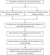
The objective of this work was to study the performance of cleaning pleated fabric cartridge filters used for collecting pesticide particles and to determine the effect of cleaning on system operational process. A pleated fabric cartridge filter was used to collect pesticide particulate matters obtained from grinding and classification. On-line pulse-jet cleaning was used to dislodge the dust cake from the filter cartridge. It was found that the required detachment forces for dislodgement of pesticide powder from the pleated cartridge are bigger than those of other particulate matters. The pesticide particles are not dislodged from the filter cartridge when the average peak pressure over the height of the filter cartridge is 2473 Pa with the induced nozzle Φ16. The bottoms of the filter cartridges remain filled with pesticide particles when the average peak pressure over the height of the filter cartridge is 3455 Pa with the nozzle Φ20. The whole filter cartridges are cleaned when the average peak pressure over the height of the filter cartridge is 4627 Pa and the systematic pressure drops of the cartridge filter with nozzle Φ25 mm are maintained at 1400 Pa. The bigger the peak pressures on pleated filter cartridge, the quicker the pesticide particles are dislodged from the filter cartridge, decreasing re-attachment of re-suspended pesticide particles onto the filter cartridge. An increase in nozzle diameter can increase the peak static pressures on the filter cartridge, solving the problem of “patchy” cleaning of pleated fabric filter cartridges used for collecting pesticide particles. The surface static pressures on the filter cartridges can give guidance as to the cleaning effect on the system stable operation in industrial applications.
1. Introduction
Superfine grinding technology is a useful tool for making ultrafine powder.1,2 Such powders have applications in many fields, such as abrasives, ceramics, electronic materials, pharmaceutics, chemistry, etc.3–7 To make ultrafine pesticide particles, superfine grinding is done using an air jet mill. Through grinding and classification, the pesticide particles have high mass concentration, ultrafine particle size and a characteristic of heat sensitivity. Effective technology is sought by many industries for collecting ultrafine pesticide particles after grinding and classification. A dust collector has been used to recover pesticide particles and to control particle emission in many industries, meeting strict environmental policy. Among collection methods, bag filters are often used because their separation technique depends only on the pore size of the filter medium. Particles are collected independent of their density, shape, and particulate size distribution when their particle sizes are larger than the pore size of the filter medium. Despite the favorable separation characteristics of bag filters, they cause significant pressure drop during industrial applications and the filter media can be easily damaged during clogging and cleaning cycles.
Recently, the use of pleated fabric filter cartridges in dust collectors has attracted great attention because the pleated filter cartridges offer a larger filtration surface compared with flat-sheet filter bags (if both filters are used in housing of the same size).8–11 In addition to increasing the filtration area, the pleated structure decreases the filtration face air velocity compared with flat-sheet filter bags. An increase in the filtration area of filter cartridges can lead to a decrease in the overall separator size and in the cost of having to replace the filter bags at regular intervals of time. However, cleaning pleated fabric filter cartridges is more difficult than cleaning flat-sheet filter bags.9,11 On-line pulse-jet cleaning has been used to dislodge the dust cake from the filters 12–14. Pulse-jet cleaning of filter cartridges leads to a reduction in the systematic pressure drop; however, on-line cleaning of filter cartridges for collecting pesticide particles is more difficult than cleaning of cartridges for other particulate matter. This is because the pesticide particles have high adhesion, low density, and fine particle size. Fig. 1 shows the patchy cleaning of pleated fabric filter cartridges for collecting pesticide particles in an industrial factory.
 |
| Fig. 1 Difficult cleaning of pleated filter cartridges for collecting pesticide particles (with induced nozzle Φ16 mm, the filter cartridges are taken out of the filters after operational time of 60 min). | |
Pleated fabric filter cartridges have characteristics of reduced deformation and better filtration efficiency compared with flat-sheet filter bags. However, little has been reported in the literature of pleated filter cartridges being applied in pulse-jet dust collectors of industrial factory. To maintain dust collectors for collecting pesticide particles from the air jet mill under a reasonable level of pressure drop, on-line pulse-jet cleaning is used for periodically dislodging the dust cake. The objective of this study is to investigate cleaning of pleated cartridge filters and the effect of cleaning on systematic operation in collecting pesticide particles.
2. Materials and methods
2.1. Experimental apparatus
Four filter cartridges (Φ325 × Φ215 × 1000 mm, 125 pleat count) were installed in a dust collector. Fig. 2 shows a schematic view of the test rig (designed by Mianyang, Liuneng, Powder Equipment Co., Ltd.). The dimensions of the dust collector compartment were Φ1260 × 3150 mm, as shown in Fig. 3. The filter cartridge dimensions are shown in Table 1. A photo and microstructure of filter cartridges is shown in Fig. 4a. A rigid wire cage supported the filter medium, as shown in Fig. 4b. The filter medium was coated with a layer membrane of fine polytetrafluoroethylene fibers, which has hydrophobic and oleophobic properties, and is resistant to acid and alkali. The induced pulse airflow was produced by a supersonic induced nozzle (VN25PC-50, Australia, Goyen Co., Ltd.) and an air diffuser (CC200, Australia, Goyen Co., Ltd.). Schematic diagrams of the induced nozzle and the diffuser are shown in Fig. 5. The experiment also included a pulse valve (DMF-Z-50 s type with diameter 2′′), a compressed air reservoir, a pulse controller, a screw air compressor, five high precision pressure transducers (S130100), an electric charge amplifier (QSY7709), a portable data acquisition instrument (QSY-USB-8512E), and an anemoscope (SwemaAir50). A hopper was connected to the dust cartridge filter to collect the dust dislodgement from the filter cartridge.
 |
| Fig. 2 Schematic view of the test rig. | |
 |
| Fig. 3 Photos of equipment (a) dust collector and pulse jet, (b) hopper. | |
Table 1 Filter cartridge dimension
Parameters |
Pleat number (n, ↑) |
125 |
Pleat pitch (W, mm) |
8.164 |
Pleat height (H, mm) |
45 |
Inner diameter (Din, mm) |
215 |
Filter length (L, mm) |
1000 |
Filtration area (Af, m2) |
12 |
Surface treatment |
Polytetrafluoroethene fibers |
Thickness of filter medium (mm) |
0.6 |
Air permeability (m−2 s−1) |
80–100 |
 |
| Fig. 4 Filter cartridge (a) photo of filter cartridge and microstructure of filter medium, (b) a rigid wire cage support the filter medium. | |
 |
| Fig. 5 Photo and schematic diagram of supersonic induced nozzle and the air diffuser (a) photo of supersonic induced nozzle, (b) photo of air diffuser, (c) schematic view of supersonic induced nozzle and air diffuser. | |
The fabric microstructure of the pleated filter cartridge was determined using a scanning electron microscope (Leica 440). Five high precise pressure transducers were used to monitor the static peak pressure on the surface of the filter cartridge. The pulse airflow from the compressed air reservoir was controlled using a pressure regulator, a pulse valve, and a sequential timer/relay that changed the pulse valve opening time and interval. A computer running the LabView program was connected to a charge amplifier and a data acquisition instrument to collect the data. A pulse controller was connected to control the pulse valve.
2.2. Dust test
In this experiment, a pleated cartridge filter was used to collect pesticide particles. Through grinding and classification, the particle size distribution of the particles was 0.5–5 μm (d10 = 0.73 μm, d50 = 1.61 μm and d90 = 2.68 μm). Inlet particle mass concentration of the dust collector was 107 g m−3. The pesticide particles have characteristics of adhesion and chemical corrosion, therefore, stainless steel was used to make the dust collector, reducing the amount of pesticide particles that adhered to its wall.
2.3. Filtration and cleaning processes
An induced draft fan produced systematic negative pressure during the particle collection process. Through grinding and classification, the pesticide particles were collected on the filter medium using the induced draft fan. Each filter cartridge was fitted with a compressed air injection nozzle and a pulse valve. The filter cartridges were cleaned with a pulse jet injection of compressed air. The pulse airflow was in the opposing direction to the normal forward flow of filtration through the dust collector. Re-suspension of detached particles occurred after the pulse-jet cleaning. The detached particles went into the hopper because of the heavy force and reverse pulse airflow. Dry air obtained from the cold and dry machine was used to transport the pesticide particles and to dislodge pesticide particles from the filter cartridge.
2.4. Experimental design
On the basis of production yields of the air jet mill and pesticide properties, the filtration velocity was set to 0.7 m min−1. The pressure drops of the pleated fabric cartridge filter were measured using a transmitter, and the cleaning mode was clean on time. The experimental designs are shown in Table 2. Pressure transducers (Φ7 mm) were fixed on the interface of the rigid wire cage on the filter surfaces, with the size of the pressure transducers being smaller than that of the filter cartridge; therefore, the effect of the pressure transducers on the airflow could be ignored. Measurements one, two, three, four, and five were positioned 80 mm, 150 mm, 350 mm, 650 mm, and 850 mm, respectively, from the top of filter cartridge. Pressure transducers were positioned at each measurement point. Export signals from the pressure transducer were connected to the import signal from the charge amplifier. The outlet of the charge amplifier was then linked to the inlet of the data acquisition instrument. Finally, the export signal from the data acquisition instrument was linked to the computer. The systematic connection method of pressure transducers is shown in Fig. 6. In the data analysis phase, Microsoft dasView2.0 was employed to acquire and change the data into the pressure data based on sensor sensitivity using the following formula (1): |
 | (1) |
where P (MPa) is the measured pressure; v (mV) is voltage output value; K1 (mv pC−1) is a multiple of the charge amplifier; and K2 (pC MPa−1) is the sensor sensitivity.
Table 2 Experimental designs
Test conditions |
Settings |
Filter face velocity (m min−1) |
0.7 |
Inlet particle mass concentration (g m−3) |
100 |
Cleaning modes |
Clean on time (10 s once) |
Tank pressure (MPa) |
0.6 |
Pulse valve opening time (ms) |
100 |
Pulse flow (L) |
80 |
Induced nozzle diameter (mm) |
16 |
Nozzle diameter (mm) |
20 or 25 |
Distance between induced nozzle and filter cartridge top (mm) |
50 |
Diffuser height (mm) |
102 |
 |
| Fig. 6 Systematic connection method. | |
3. Results and discussion
3.1. Effect of nozzle diameter on cleaning performance of pleated filter cartridge
To optimize the relationship between nozzle diameter and jet distance, an experiment was done to obtain the optimum jet distance. In our previous study, static peak pressures on the filter cartridge were an important indicator of cleaning performance11,15–17. Therefore, the static peak pressure on the filter cartridge was chosen as an index of cleaning effect in this study. Fig. 7–9 show the optimum jet distances obtained under three different nozzle diameters. The optimum jet distances of nozzle orifice Φ20 mm and Φ25 mm are 280 mm and 200 mm, respectively. This is because the bigger the nozzle diameter, the shorter the jet distance needed to disperse the pulse airflow, as shown in Fig. 10. The optimum jet distance of the induced nozzle Φ16 mm is 60 mm, because the induced nozzle has a height of 168 mm. The induced nozzle changes the pulse airflow streamlines. Fig. 5 shows that the pulse airflow goes through the supersonic induced nozzle and encounters the wall of the air diffuser, at which the pulse airflow beam begins to disperse. Therefore, the optimum jet distance of induced nozzle Φ16 mm is shorter than the common nozzle orifice Φ16 mm.
 |
| Fig. 7 Effect of jet distance on peak pressure with the induced nozzle Φ16 mm. | |
 |
| Fig. 8 Effect of jet distance on peak pressure with the nozzle orifice Φ20 mm. | |
 |
| Fig. 9 Effect of jet distance on peak pressure with the nozzle orifice Φ25 mm. | |
 |
| Fig. 10 Nozzle orifice and jet distance. | |
Fig. 11 shows that the static peak pressure distribution varies over the height of filter cartridge under three different nozzles. The figure shows that a nozzle orifice Φ25 mm can produce bigger static peak pressures than those of a nozzle orifice Φ20 mm. The average peak pressure over the height of the filter cartridge is 4627 Pa using a nozzle orifice Φ25 mm, and the average peak pressure over the height of the filter cartridge is 3455 Pa using a nozzle orifice Φ20 mm, as an increase in nozzle orifice can increase the pulse airflow velocity. This pulse airflow creates a low-pressure zone and generates momentum in the surrounding fluid. The bigger the nozzle orifice, the more secondary airflow is induced into the filter cartridge. The mixture of pulse airflow and secondary airflow goes into the filter cartridge, and the dynamic pressures are converted to static pressures when the mixed airflow encounters the wall of the filter cartridge. Therefore, the formed static pressures on a filter cartridge with nozzle orifice Φ25 mm are bigger than those of a cartridge with nozzle orifice Φ20 mm. The bigger the nozzle orifice, the bigger the axial velocity of the mixed airflow, hence more airflow goes to the bottom of the filter cartridge. The peak pressures at the bottom of the filter cartridge are bigger than in other areas.
 |
| Fig. 11 Peak pressures over the full height of the filter cartridge with three different nozzles (induced nozzle Φ16 mm with jet distance 60 mm, nozzle Φ20 mm with 280 mm, nozzle Φ25 mm with jet distance 200 mm). | |
However, the peak pressure distribution of a filter cartridge with induced nozzle Φ16 mm is different from those with nozzle orifices Φ20 mm and Φ25 mm. This is because the airflow streamlines are changed by the induced nozzle. The average peak pressure over the height of the filter cartridge is 2473 Pa using the induced nozzle Φ16 mm. In our previous study, static peak pressure distribution on the filter cartridge was changed by induced airflow.11 This is because the pulse airflow through the induced nozzle with the surrounding airflow goes onto the air diffuser, the mixed airflow streamlines are changed and form a bigger airflow beam with the air diffuser than they do without, when they encounter the wall of air diffuser. Therefore, the optimum jet distance is shorter with the induced nozzle than without the induced nozzle. The airflow goes down and is introduced into the surrounding fluid. Then the mixed airflow goes into the filter cartridge. Therefore, the bigger airflow beam forms static pressures from the top to the bottom of the filter cartridge. The results agree with results obtained in our previous study.11
3.2. Systematic pressure drops during clogging and cleaning cycles
The inlet particle mass concentration of the dust collector is 107 g m−3, suitable for grinding and classification, and the filtration velocity was set to 0.7 min m−1 using an induced draft fan. The pesticide particles were filtered on filter cartridges, with a reverse pulse-jet airflow used to dislodge the pesticide particles from the filter cartridges. As the clogging and cleaning cycles progress, the systematic pressure drops vary with the operational time, as shown in Fig. 12. An increase in nozzle orifice can reduce these systematic pressure drops. The pressure drop of a cartridge filter with induced nozzle Φ16 mm quickly increases to 2000 Pa when the system operational time is 60 min. At this time, the four filter cartridges were taken out of the dust collector; the four filter cartridges were filled with pesticide particles as shown in Fig. 1. This is because the detachment forces were not sufficient to dislodge the pesticide particles from the filter cartridges. Fig. 10 shows that the peak pressure at measurement two is 4217 Pa and the average peak pressure is 2473 Pa using the induced nozzle Φ16 mm. The dust cakes at measurement two were dislodged from the filter cartridges; however, the dust cakes at the other measurement points were not dislodged from the filter cartridges during the operational times. At the operational times, the filter cartridges were gradually filled with the dust cakes at measurements one, three, four and five. Therefore, the filtration velocities greatly increase at measurement two. The systematic pressure drops greatly increase with increasing operational times. As the cycles progress, the systematic pressure drops quickly increase to 2000 Pa. Finally, all filter cartridges are filled with dust cakes, as shown in Fig. 1. This experimental result is different from the result obtained in our previous study,11 because the collected particle matters are different. In this study, the pesticide particles have characteristics of high adhesion, low density, and fine particle size (d10 = 0.73 μm, d50 = 1.61 μm and d90 = 2.68 μm). Therefore, the detachment forces were not sufficient to dislodge the pesticide particles from the filter cartridge under the same conditions as in the previous study. In that study,11 pleated filter cartridges were used to collect protein powder from the grinding. The particle size distribution of the protein powder was d10 = 2.58 μm, d50 = 11.24 μm, and d90 = 28.72 μm. The inlet particle concentration of the dust collector was 19.5 g m−3, and the detachment forces were sufficient to dislodge the protein powder from the filter cartridges. Therefore, bigger detachment forces are needed to dislodge pesticide particles than other common particles. The biggest induced nozzle diameter is Φ16 mm in industry production. Therefore, an increase in nozzle orifice was used to increase the detachment forces in this study.
 |
| Fig. 12 Systematic pressure drops vs. operational time during clogging/cleaning cycles. | |
Fig. 13 shows that the bottom areas of the four filter cartridges with nozzle orifice Φ20 mm are filled with pesticide particles when the operational time is 150 min. This is because the detachment forces were sufficient to dislodge the particles from the filter cartridges. During pulse-jet cleaning, the dislodged particles go into the hopper because of the heavy force and reverse pulse-jet airflow. However, as the filtration progresses, re-suspended particles re-attach to the filter cartridges, particularly at the bottom. As the nozzle orifice is increased, pesticide particle dislodgement from the filter cartridge is promoted, as shown in Fig. 11. The systematic pressure drops of a cartridge filter with nozzle Φ25 mm increase gradually to 1400 Pa when the system operational time is 100 min, and then the pressure drops are maintained. Fig. 14 shows that pesticide particles are dislodged from filter cartridges with nozzle orifice Φ25 mm when the operational time is 200 min. This is because the detachment forces are sufficient to dislodge the pesticide particles and reinforce the pesticide particles into the hopper. The re-suspended particles are given no chance to attach to the filter cartridge.
 |
| Fig. 13 Bottom of filter cartridge filled with dust particles using the nozzle Φ20 mm (views from the bottom after operational time 150 min). | |
 |
| Fig. 14 Bottom of filter cartridge filled with dust particles resolved using the nozzle Φ25 mm (views from the bottom after operational time 180 min). | |
However, Fig. 11 shows that the static peak pressure distribution over the full height of the filter cartridge is not uniform with nozzle orifice Φ25 mm. Although the pesticide particles were dislodged from the filter cartridge, uniform peak pressure distribution is needed to conserve the energy and to decrease damage to the filter medium. Therefore, our next goal is to seek an induced nozzle with diameter Φ25 mm, which will be used to collect particle matters with characteristics of high adhesion, low density, and fine particle size.
3.3. Peak pressures of filter cartridge with operational time
Fig. 15–17 show that the peak pressures on the filter cartridge vary with extension of operational time. The peak pressure is indicative of cleaning performance. The bigger the static peak pressures, the bigger the detachment forces. From Fig. 15, the static peak pressures over the height of the filter cartridge decrease quickly with the induced nozzle Φ16 mm. As the clogging and cleaning cycles progress, the detachment forces are not sufficient to dislodge the pesticide particles from the filter cartridge. The filter cartridges are quickly clogged by pesticide particles, and the pulse airflow does not reach clogged areas of filter medium. Then the peak pressures decrease quickly on the clogged filter cartridges, and the systematic pressure drops increase quickly to 2000 Pa, as shown in Fig. 12, and the filter cartridges are filled with pesticide particles, as shown in Fig. 1. Fig. 16 shows that the peak pressures on the bottom of filter cartridge decrease quickly with the nozzle orifice Φ20 mm. This is because the bottom areas of filter cartridge are gradually clogged by the pesticide particles, and, therefore, the peak pressure at the bottom areas of the filter cartridge decrease. The systematic pressure drops increase gradually to 1800 Pa, as shown in Fig. 12, and the bottom areas of the filter cartridge are filled with pesticide particles, as shown in Fig. 13. Fig. 16 shows that the peak pressures on the bottom of the filter cartridge decrease a little with the nozzle orifice Φ25 mm. The pesticide particles are dislodged from the filter cartridges. Therefore, the systematic pressure drops maintain a constant value. The bigger the peak pressures on filter cartridges, the bigger the detachment forces formed to dislodge the pesticide particles.
 |
| Fig. 15 Effect of operational time on peak pressure with the induced nozzle Φ16 mm. | |
 |
| Fig. 16 Effect of operational time on peak pressure with the nozzle orifice Φ20 mm. | |
 |
| Fig. 17 Effect of operational time on peak pressure with the nozzle orifice Φ25 mm. | |
4. Conclusions
An increase in nozzle diameter can increase peak pressures over the full height of a filter cartridge. The average peak pressures increase from 2471, 3455 to 4627 Pa when the nozzles are changed from the induced nozzle 16 mm, the nozzle Φ20 to the nozzle Φ25. Additionally, the systematic pressure drops of the cartridge filter stay at 1400 Pa with nozzle Φ25 mm at operational time 180 min. Pulse-jet cleaning with nozzle orifice Φ25 mm can effectively dislodge pesticide particles from the filter cartridge. However, the peak pressure distribution over the full height of the filter cartridge with nozzle orifice Φ25 mm is not uniform. Our next goal is to seek an induced nozzle with diameter Φ25 mm, which will be used to collect particle matter.
The peak pressures on a filter cartridge can reflect the clogged process of filter medium with operational time. Patchy cleaning is related to a decrease in peak pressures on a filter cartridge. Combined with systematic pressure drops and photos of the filter cartridge in industrial applications, the peak pressure is an effective indicator of cleaning performance.
Herein, the performance of cleaning a pleated fabric filter cartridge used for collecting pesticide particles and the effect of cleaning on systematic pressure drops were determined. This study could aid in solving problems associated with cleaning pleated fabric filter cartridges used for collecting particle matter with characteristics of higher adhesion, lower density, and finer particle size.
Acknowledgements
This work is supported by the Doctor's Fund of Southwest University of Science and Technology (no. 14ZX7127), and was also supported by the Key Scientific Research Platform of Southwest University of Science and Technology (no. 14tdgk04).
References
- G. C. Wu, M. Zhang, Y. Q. Wang, K. J. Mothibe and W. X. Chen, Production of silver carp bone powder using superfine grinding technology: Suitable production parameters and its properties, J. Food Eng., 2012, 109, 730–735 CrossRef PubMed.
- K. Tkacova and N. Stevulova, Selected problems of the dispersity analysis of milled ultrafine powders, Freiberger Forsclungshefte A A841 (Partikeltechnologie), ( 1998), pp. 14–25.
- A. C. Bentham, C. C. Kwan and R. Boerefijn, Fluidised-bed jet milling of pharmaceutical powders, Powder Technol., 2004, 141, 233–238 CrossRef CAS PubMed.
- S. Y. Jin and H. Z. Chen, Superfine grinding of steam-exploded rice straw and its enzymatic hydrolysis, Biochem. Eng. J., 2006, 30, 225–230 CrossRef CAS PubMed.
- N. Midouxa, P. Hošek, L. Pailleres and J. R. Authelin, Micronization of pharmaceutical substances in a spiral jet mill, Powder Technol., 1999, 104(2), 113–120 CrossRef.
- V. Rodnianski, N. Krakauer, K. Darwesh, A. Levy, H. Kalman, I. Peyron and F. Ricard, Aerodynamic classification in a spiral jet mill, Powder Technol., 2013, 243, 110–119 CrossRef CAS PubMed.
- W. Schlocker, S. Gschließer and A. Bernkop-Schnürch, Evaluation of the potential of air jet milling of solid protein-poly (acrylate) complexes for microparticle preparation, Eur. J. Pharm. Biopharm., 2006, 62(3), 260–266 CrossRef CAS PubMed.
- N. Hasolli, Y. O. Park and Y. W. Rhee, Filtration performance evaluation of depth filter media cartridges as function of layer structure and pleat count, Powder Technol., 2013, 273, 24–31 CrossRef PubMed.
- L. M. Lo, D. R. Chen and Y. H. Pui David, Experimental study of pleated fabric cartridges in a pulse-jet cleaned dust collector, Powder Technol., 2010, 197, 141–149 CrossRef CAS PubMed.
- M. Rebaia, M. Prata, M. Meirelesc, P. Schmitze and R. Baclet, Clogging modeling in pleated filters for gas filtration, Chem. Eng. Res. Des., 2010, 88, 476–486 CrossRef PubMed.
- C. P. Yan, G. J. Liu and H. Y. Chen, Effect of induced airflow on the surface static pressure of pleated fabric filter cartridges during pulse jet cleaning, Powder Technol., 2013, 249, 424–430 CrossRef CAS PubMed.
- A. Kavouras and G. Krammer, A model analysis on the reasons for unstable operation of jet-pulsed filters, Powder Technol., 2005, 154, 24–32 CrossRef CAS PubMed.
- Z. Bai and D. Y. Zhang, Cleaning pressure characteristics and selection research of pulse filter, Environ. Prot. Metall., 2002, 6, 68–69 Search PubMed.
- X. Simon, S. Chazelet, D. Thomas, D. Bémer and R. Régnier, Experimental study of pulse-jet cleaning of bag filters supported by rigid rings, Powder Technol., 2007, 172, 67–81 CrossRef CAS PubMed.
- M. Ju, M. X. Zhang, J. D. Chen, Q. Zhang and H. Y. Chen, Dynamic analysis of dust dislodgement from pulse-jet cartridge filter, Chin. J. Environ. Eng., 2013, 7, 1091–1094 Search PubMed.
- Q. Zhang, H. Y. Chen, M. Ju and J. D. Chen, Experiment on induction nozzle improving dust-cleaning efficiency of pulse-jet cartridge filters by induction nozzles, Environ. Eng., 2012, 30, 62–65 Search PubMed.
- J. Zheng, M. X. Zhang, Q. J. Zhou, Y. Z. Zhang and G. B. Cai, Pressure peak test and analysis of membrane cartridge filter side wall, China Powder Sci. Technol., 2011, 17(1), 63–66 Search PubMed.
|
This journal is © The Royal Society of Chemistry 2015 |
Click here to see how this site uses Cookies. View our privacy policy here.