High-pressure phase behavior of 1-ethyl-3-methylimidazolium tetrafluoroborate and carbon dioxide system
Kang Qin,
Kai Wang*,
Yang Li,
Fanhe Kong and
Tao Wang*
State Key Laboratory of Chemical Engineering, Department of Chemical Engineering, Tsinghua University, Beijing 100084, China. E-mail: kaiwang@tsinghua.edu.cn; taowang@tsinghua.edu.cn; Fax: +86 10 62770304; Tel: +86 10 62788568
First published on 31st March 2015
Abstract
The phase behavior of the 1-ethyl-3-methylimidazolium tetrafluoroborate ([emim][BF4]) and carbon dioxide (CO2) system from atmospheric to supercritical state was investigated at 0.1–15.0 MPa and 308.15–343.15 K. The solubility data of CO2 in [emim][BF4] and the volumetric expansion ratios of CO2-saturated [emim][BF4] were provided. Experimental results indicated that although CO2 dissolved significantly in [emim][BF4] (from 0 to 62 mol%), the ionic liquid phase only had an expansion ratio less than 17 vol%. The density difference between CO2-saturated [emim][BF4] and pure [emim][BF4] was obvious at high pressure and low temperature, with a maximum of 16.11% at 308.15 K and 15.0 MPa. Based on the experimental results, a fitting equation applicable to precise data interpolation was proposed for the CO2-saturated [emim][BF4] density in this study.
1. Introduction
As a green solvent, carbon dioxide (CO2) in gaseous, liquidus and supercritical state is widely used.1 It has attracted much more attention in recent years due to its favorable properties and environmental benignity. Comparing with gaseous carbon dioxide, the inherent mass transfer limitations could be eliminated in supercritical carbon dioxide (ScCO2),2 resulting in improved reaction and separation efficiency. In the chemical processes involving supercritical carbon dioxide, there is a continuing interest in developing new concepts for biphasic system3 in which one phase, such as aqueous solutions,4 liquid polymers5 or ionic liquids (ILs),6 acts as the reaction solvents to immobilize catalyst, and the other phase, ScCO2, acts as a mobile phase to deliver reactants or remove products.2 In view of the volatility and solvency of liquid phase, ionic liquids are preferable choices. Ionic liquids are salts with huge liquidus range7 that composed by organic cations and inorganic or organic anions.8 Many ionic liquids are in liquid state at room temperature mainly due to the large size difference between their counter ions.9 The unique properties of the ionic liquids, such as low volatility, high thermo-stability, good solvency and weak corrosivity, have garnered them much recent attention as an efficient alternative to traditional organic solvents in some chemical reaction, separation, and manufacturing processes.10,11The biphasic system constituted by CO2 and ILs has asymmetric solubility. Carbon dioxide dissolves readily in the ionic liquids, but the ionic liquids hardly dissolve in carbon dioxide.6 Therefore, carbon dioxide can extract organic nonelectrolytes from ionic liquids without any cross-contamination. Furthermore, carbon dioxide can favorably bring reactants or gases into ionic liquids phase, as it enhances the solubility of many gases and nonpolar substances.12 The fundamental properties of ILs, such as density, viscosity, diffusivity and molar volume, can be adjusted to a certain extent with the dissolution of carbon dioxide. The solubility of CO2 and the volumetric expansion of ILs play an important role, as they are required to estimate some core parameters in the applications, such as the density, concentration and interfacial properties.
Due to the high solubility of CO2 in imidazolium-based ionic liquids,13 many experimental studies have placed emphasis on the phase behavior of imidazolium-based ionic liquids in CO2 atmosphere, including 1-ethyl-3-methylimidazolium ethyl sulfate ([emim][EtSO4]),14 1-butyl-3-methylimidazolium tetrafluoroborate ([bmim][BF4]),15 and 1-butyl-3-methylimidazolium hexafluorophosphate ([bmim][PF6]),16 et al. However, according to our knowledge, there is no report about the phase behavior of the ionic liquid constituted by 1-ethyl-3-methylimidazolium cation [emim]+ and tetrafluoroborate anion [BF4]− at high-pressure yet. The focus of this work is to develop insights into the high-pressure phase behavior of carbon dioxide with 1-ethyl-3-methylimidazolium tetrafluoroborate ([emim][BF4]), which is one of the widely used commercial imidazolium-based ionic liquids.10,17 The solubility of CO2 and the volumetric expansion of [emim][BF4] were measured at different pressures ranging from 0.1 to 15.0 MPa and different temperatures varied from 308.15 to 343.15 K. The density data of CO2-saturated [emim][BF4] were also derived with a fitting equation for precise interpolation. The results can have a profound effect on understanding other physical properties, which depend strongly on the density difference between the two phases.4
2. Experimental
2.1. Apparatus
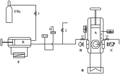
A schematic diagram of the experimental set-up is shown in Fig. 1. The main part of this apparatus was a high-pressure viewing cell with sapphire windows (A, EC600, Separex, France, designed for a maximum pressure of 70 MPa). The maximum inner volume of the high-pressure cell is 45 mL. Pushing the piston placed in the cell decreases the cell volume from 45 to 15 mL. A “dead volume” of 15 mL corresponds to the lower part of the cell where the piston cannot go. The variable inner volume of the high-pressure cell is real-time displayed on the computer. The stroke of the piston is 100 mm, while the precision of the stroke measurement certified by the manufacturer is less than 0.1 mm. The temperature in the viewing cell can be accurately controlled by an oil bath jacket (B, CC304, Huber, Germany) and monitored by a temperature probe embedded in the center of the cell with fluctuation less than 0.01 K. A CMOS camera (C, 1080P, Microsoft, USA) was used to capture the phase interface between CO2 and [emim][BF4] with the help of a light source perpendicular to it. A syringe pump (E, P100, Separex, France) was used to deliver the high pressure CO2 into the viewing cell. The cooling bath jacket (F, IL00805, STIK, USA) and the volume scale on the pump helped to control the feeding amount of liquid CO2. The pressure in the viewing cell was measured with a calibrated, precision pressure transducer (absolute error of 0.01 MPa) and adjusted by the feeding quantity of CO2 together with the variable volume piston placed in the cell. In the measurements, CO2 of purity 99.999 wt% (BW GAS, China), [emim][BF4] of purity 99.95 wt% (CJC, China), cumene of purity 99 wt% (Aladdin, China) and deionized water of electro-conductibility 1 μS cm−1 (JC EET, China) were used as the reagents. The water content of [emim][BF4] was checked by the Karl Fischer moisture meter (C30, Mettler-Toledo, USA) prior to each measurement. | ||
| Fig. 1 Schematic diagram of the experimental apparatus: (A) viewing cell; (B) oil bath; (C) camera; (D) light source; (E) syringe pump; (F) cooling bath; (G) rupture disk. | ||
2.2. Experimental procedure
The viewing cell was initially filled with 7 mL [emim][BF4] to reach the bottom of the sapphire window, so that the liquid level could be detected by the camera. Then low pressure CO2 was pumped through the whole cell and connecting lines to displace any air present. After gas replacement, the outlet of the viewing cell was closed and high pressure CO2 was fed in. For a constant temperature, the measurements were conducted from 0.1 MPa to 15.0 MPa. The pressure in the viewing cell was increased by adding CO2 up to the desired value. After the feeding of CO2, the maximum duration of time required for the system to reach equilibrium was 90 min, that is, no changes in pressure and liquid level could be detected after this time. The height of CO2/[emim][BF4] interface at equilibrium was captured and used to calculate the liquid volume, which has already been calibrated before experiment. The volumetric expansion ratio EL(%) of [emim][BF4] at a given pressure P (MPa) and temperature T (K) was defined as:
 | (1) |
For each pressure increment, the initial condition (pressure, temperature and volume) and equilibrium condition (pressure, temperature and volume) were recorded to determine the density of CO2 from NIST Chemistry WebBook (http://webbook.nist.gov/chemistry/), respectively. The mass of CO2 dissolved in the [emim][BF4] during the i th pressure increment, with the expression of miG (kg), was calculated using the following equation:
| miG (kg) = ρ0G(T0, P0) × (V0C − V0L) − ρeG(Te, Pe) × (VeC − VeL) | (2) |
Accordingly, the mass of CO2 dissolved in per unit mass of [emim][BF4] at a given pressure P (MPa) and temperature T (K), with the expression of SG (kg kg−1), could be calculated using the following equation:
 | (3) |
The mole fraction XG (%) of CO2 dissolved in the [emim][BF4] at a given pressure P (MPa) and temperature T (K) was then given by:
 | (4) |
Finally, the saturated density of liquid phase (CO2-saturated [emim][BF4]) ρL (kg m−3) at a given pressure P (MPa) and temperature T (K) could be obtained from the following equation:
 | (5) |
2.3. Calibration and accuracy of the measurements
The upper part of the high-pressure cell where the piston reciprocating (from 15 to 45 mL) is cylindrical in shape, so the inner diameter does not change with inner height. However, the lower part of the cell (from 0 to 15 mL) where the ionic liquids filled is irregularly-shaped due to the flat sapphire window and the embedded temperature probe, so the inner diameter actually changes with inner height. In order to find the relation of inner diameter to inner height, in other words, the relation between the liquid volume and the level height of CO2/[emim][BF4] interface, calibration had to be taken before the volumetric expansion measurement. The calibration process was conducted using water, ionic liquids ([emim][BF4]) and cumene, so that the influence of solvent viscosity, volatility, and the liquid meniscus on the height of liquid level could be detected and offset with mathematic correction. Eventually, a calibration curve with more than 200 experimental points was established to determine the liquid volume as a function of the height of CO2/[emim][BF4] interface. In order to verify the accuracy of the measurements, the volumetric expansion ratios of CO2-saturated cumene (EL) and the solubility data of CO2 in cumene (XG) were measured and compared with the data reported by Phiong and Lucien.19 Table 1 gives the relative deviations between experimental data and the literature data.19 According to this comparison, the relative deviations are less than 5%.| P (MPa) | Literature data (%) | Experimental data (%) | Relative deviation (%) | |||
|---|---|---|---|---|---|---|
| EL | XG | EL | XG | EL | XG | |
| 3.02 | 12.2 | 22.34 | 11.60 | 21.59 | −4.92 | −3.36 |
| 5.00 | 26.5 | 39.27 | 25.96 | 38.42 | −2.04 | −2.16 |
| 7.01 | 58.5 | 58.16 | 61.33 | 60.63 | 4.84 | 4.25 |
| 8.02 | 98.2 | 71.12 | 98.37 | 72.04 | 0.17 | 1.29 |
| 8.50 | 143.2 | 79.57 | 146.51 | 82.70 | 2.31 | 3.93 |
| 8.81 | 204.9 | 83.91 | 199.74 | 83.25 | −2.52 | −0.79 |
3. Results and discussion
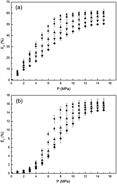
The solubility data of CO2 in [emim][BF4] and the volumetric expansion ratios of CO2-saturated [emim][BF4] were shown in Fig. 2(a) and (b), respectively. Five isotherms at 308.15 K, 313.15 K, 323.15 K, 333.15 K and 343.15 K were measured from 0.1 MPa to 15.0 MPa. In order to obtain high accuracy and reproducibility for the measurements, every isotherm has been measured at least ten times to determine the average values and the error bars. It can be seen from Fig. 2 that although CO2 dissolved significantly in [emim][BF4] (range from 0 to 62 mol%), the IL phase did not expand substantially (EL ranges from 0 to 17 vol%) compared with that of common hydrocarbons (e.g. cumene19). The low volumetric expansion ratio should be resulted from the strong Coulombic forces between the ions and the moderate asymmetry of the cations in ILs,16 which form a relatively large skeleton and provide lots of inner spaces for CO2 to dissolve without significant volumetric changes. The experimental solubility data of CO2 in [emim][BF4] are slightly lower than ones in [bmim][BF4] (1-butyl-3-methylimidazolium tetrafluoroborate) reported in literature,20 which is reasonable as the anion of ILs dominates the interactions with CO2 (ref. 13) and that increasing alkyl chain length of cation marginally increased the CO2 solubility in ILs.15The increase of solubility and volumetric expansion with rising pressure could be divided into three stages. For the initially low pressure area, the solubility of CO2 in the IL phase increases dramatically with increasing pressure, reaching 32.14% mole percent CO2 at 308.15 K and 4.0 MPa. Meanwhile, the volume of the IL phase just increases by 2.53% at the same condition. This discrepancy can be attributed to the “free volume” or “void space” available in the IL phase14 which facilitate the dissolution of CO2 without any significant volumetric expansion. As pressure further rises, the unoccupied void space in the IL phase decreases and the intrinsic Coulombic forces between [BF4]− and [BF4]− are weakened by the weak Lewis acid–base complexes formed between CO2 and [BF4]−.21 The two reasons mentioned above lead to a relatively significant increase of the volumetric expansion ratio with increasing CO2 solubility. At higher pressures, the void space within the IL phase is almost saturated, and no more CO2 can dissolve into the IL according to the “space-filling mechanism”.14 Therefore, both the solubility of CO2 and the volumetric expansion of the IL phase plateau gradually and remain basically unchanged with increasing pressure. Temperature has been known to have a remarkable influence on the gas–liquid equilibrium. Generally, an increase of gas solubility may be expected when temperature decreases. In accordance with the general gas–liquid equilibrium, reducing temperature results in an increase of the CO2 solubility as well as the volumetric expansion ratio of [emim][BF4], as shown in Fig. 2.
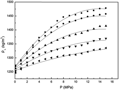
Based on the solubility data and volumetric expansion ratios mentioned above, the densities of CO2-saturated [emim][BF4] were calculated from eqn (5) and given in Fig. 3. The density of pure [emim][BF4] at atmospheric pressure (ρ*L) was derived from Seki et al.18 It can be seen from Fig. 3 that for all isotherms the density of CO2-saturated [emim][BF4] was higher than that of pure [emim][BF4]. This was due to the fact that the IL phase volume did not expand equivalently as the dissolution of CO2. The deviation between the pure and the CO2-saturated [emim][BF4] densities was large at high pressures and low temperatures, with a maximum of 16.11% at 308.15 K and 15.0 MPa.
 | ||
| Fig. 3 Density of CO2-saturated [emim][BF4] (ρL) as a function of pressure (P) at various temperatures: experimental data for 308.15 K (■), 313.15 K (●), 323.15 K (▲), 333.15 K (▼) and 343.15 K (♦). Fitting curves (solid line) were derived from eqn (6). | ||
A fitting equation was empirically proposed to correlate the saturated density data in this work. It allows the data in the experimental range to be interpolated with high accuracy. The polynomial fitting equation is given as follows:
| ρL = C0 + C1P + C2T + C3PT + C4P2 + C5PT2 + C6P2T | (6) |
| Coefficient | Unit | Value |
|---|---|---|
| C0 | kg m−3 | 1.3924 × 10³ |
| C1 | kg m−3 MPa−1 | 4.8029 × 10² |
| C2 | kg m−3 K−1 | −4.0341 × 10⁻¹ |
| C3 | kg m−3 MPa−1 K−1 | −2.2168 |
| C4 | kg m−3 MPa−2 | −8.7578 |
| C5 | kg m−3 MPa−1 K−2 | 2.4484 × 10⁻³ |
| C6 | kg m−3 MPa−2 K−1 | 2.5013 × 10⁻² |
Comparisons of the experimental data (scatter) with the fitting curves (solid line) were shown in Fig. 3. The correlation yields values with a quality of reproduction above 99.26%.
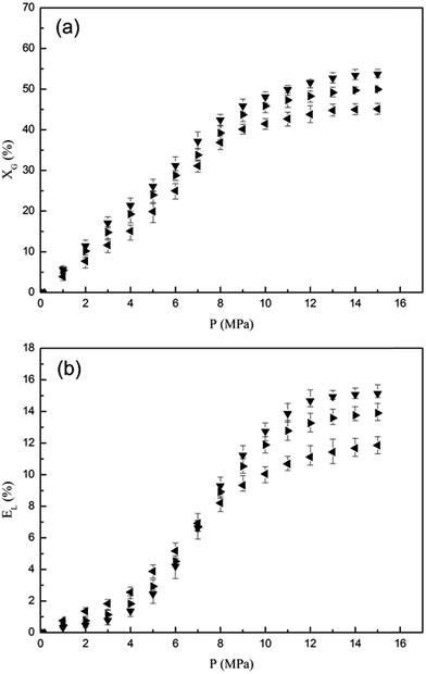
For the [emim][BF4] used in the experiment above, the water content can be neglected (below 0.05 wt%). However, due to the extremely hygroscopic properties of the imidazolium-based ionic liquids,22 it is practical to realize the effect of water in [emim][BF4] on its phase behavior with CO2. In Fig. 4, the phase behavior of CO2 with dry [emim][BF4] and [emim][BF4] solutions contained 5 wt% and 15 wt% water were depicted as a function of pressure at 333.15 K. Comparison of the three systems showed the water content would slightly lower the solubility of CO2 in [emim][BF4] phase. This decrease should be attributed to the low mutual solubility of water and CO2![[thin space (1/6-em)]](https://www.rsc.org/images/entities/char_2009.gif) 23 together with the pH reduction followed by carbonic acid formation.24 As we discussed above, the increase of solubility and volumetric expansion with rising pressure could be divided into three stages. The first stage was shortened with increasing water content because the water aggregates formed by hydrogen bonding intruded into the inherent structure of [emim][BF4].25 The resulting decrease of the unoccupied void space in [emim][BF4] phase and the intrinsic Coulombic forces between anions led to a relatively synchronous trend of the volumetric expansion ratio with the CO2 solubility, so a crossing point of the volumetric expansion curves was observed in Fig. 4(b).
23 together with the pH reduction followed by carbonic acid formation.24 As we discussed above, the increase of solubility and volumetric expansion with rising pressure could be divided into three stages. The first stage was shortened with increasing water content because the water aggregates formed by hydrogen bonding intruded into the inherent structure of [emim][BF4].25 The resulting decrease of the unoccupied void space in [emim][BF4] phase and the intrinsic Coulombic forces between anions led to a relatively synchronous trend of the volumetric expansion ratio with the CO2 solubility, so a crossing point of the volumetric expansion curves was observed in Fig. 4(b).
4. Conclusions
Experimental results are present for the solubility data of CO2 in [emim][BF4] and the volumetric expansion ratios of CO2-saturated [emim][BF4] over the pressure and temperature ranges of (0.1 to 15.0) MPa and (308.15 to 343.15) K. The relatively high solubility of CO2 (range from 0 to 62 mol%) and low volumetric expansion of [emim][BF4] (range from 0 to 17 vol%) result in an increase of [emim][BF4] saturated density. The high pressure and low temperature promote the dissolution process, so the maximum deviation between the pure and the CO2-saturated [emim][BF4] densities is 16.11% at 308.15 K and 15.0 MPa. A fitting equation was empirically proposed to offer a interpolation for the CO2-saturated [emim][BF4] density with the relative deviations less than 0.74%. The water impurity in [emim][BF4] would slightly lower the solubility of CO2 in [emim][BF4] phase, while the volumetric expansion curves of CO2-saturated [emim][BF4] become flatter with increasing water contents.Acknowledgements
The authors acknowledge gratefully the National Natural Science Foundations of China (Grant no. 21076111, 91334201) and the National Excellent Doctoral Dissertation Author Foundation of China (FANEDD 201349) for the financial support of this research.References
- Z. Yang, M. Li, B. Peng, M. Lin and Z. Dong, J. Chem. Eng. Data, 2012, 57, 1305–1311 CrossRef CAS.
- A. Ahosseini, W. Ren and A. M. Scurto, Ind. Eng. Chem. Res., 2009, 48, 4254–4265 CrossRef CAS.
- F. C. Liu, M. B. Abrams, R. T. Baker and W. Tumas, Chem. Commun., 2001, 5, 433–434 RSC.
- A. Hebach, A. Oberhof and N. Dahmen, J. Chem. Eng. Data, 2004, 49, 950–953 CrossRef CAS.
- D. J. Heldebrant, H. N. Witt, S. M. Walsh, T. Ellis, J. Rauscher and P. G. Jessop, Green Chem., 2006, 8, 807–815 RSC.
- L. A. Blanchard, D. Hancu, E. J. Beckman and J. F. Brennecke, Nature, 1999, 399, 28–29 CrossRef PubMed.
- J. S. Wilkes, Green Chem., 2002, 4, 73–80 RSC.
- P. Jaeger and R. Eggers, Chem. Eng. Prog., 2009, 48, 1173–1176 CrossRef CAS PubMed.
- Y. S. Kim, W. Y. Choi, J. H. Jang, K. P. Yoo and C. S. Lee, Fluid Phase Equilib., 2005, 228, 439–445 CrossRef PubMed.
- C. P. Fredlake, J. M. Crosthwaite, D. G. Hert, S. Aki and J. F. Brennecke, J. Chem. Eng. Data, 2004, 49, 954–964 CrossRef CAS.
- H. B. Xing, T. Wang and Y. Y. Dai, J. Supercrit. Fluids, 2009, 49, 52–58 CrossRef PubMed.
- F. Jutz, J. Andanson and A. Baiker, Chem. Rev., 2011, 111, 322–353 CrossRef CAS PubMed.
- C. Cadena, J. F. Anthony, J. K. Shah, T. I. Morrow, J. F. Brennecke and E. J. Maginn, J. Am. Chem. Soc., 2004, 126, 5300–5308 CrossRef CAS PubMed.
- L. A. Blanchard, Z. Y. Gu and J. F. Brennecke, J. Phys. Chem. B, 2001, 105, 2437–2444 CrossRef CAS.
- S. N. V. K. Aki, B. R. Mellein, E. M. Saurer and J. F. Brennecke, J. Phys. Chem. B, 2004, 108, 20355–20365 CrossRef CAS.
- D. B. Fu, X. W. Sun, J. J. Pu and S. Q. Zhao, J. Chem. Eng. Data, 2006, 51, 371–375 CrossRef CAS.
- Z. Lei, J. Yuan and J. Zhu, J. Chem. Eng. Data, 2010, 55, 4190–4194 CrossRef CAS.
- S. Seki, S. Tsuzuki, K. Hayamizu, Y. Umebayashi, N. Serizawa, K. Takei and H. Miyashiro, J. Chem. Eng. Data, 2012, 57, 2211–2216 CrossRef CAS.
- H. S. Phiong and F. P. Lucien, J. Supercrit. Fluids, 2003, 25, 99–107 CrossRef CAS.
- A. L. Revelli, F. Mutelet and J. N. Jaubert, J. Phys. Chem. B, 2010, 114, 12908–12913 CrossRef CAS PubMed.
- S. G. Kazarian, B. J. Briscoe and T. Welton, Chem. Commun., 2000, 20, 2047–2048 RSC.
- S. Cuadrado-Prado, M. Dominguez-Perez, E. Rilo, S. Garcia-Garabal, L. Segade, C. Franjo and O. Cabeza, Fluid Phase Equilib., 2009, 278, 36–40 CrossRef CAS PubMed.
- M. B. King, A. Mubarak, J. D. Kin and T. R. Bott, J. Supercrit. Fluids, 1992, 5, 296–302 CrossRef CAS.
- K. L. Toews, R. M. Schroll, C. M. Wai and N. G. Smart, Anal. Chem., 1995, 67, 4040–4043 CrossRef CAS.
- T. Takamuku, Y. Kyoshoin, T. Shimomura, S. Kittaka and T. Yamaguchi, J. Phys. Chem. B, 2009, 113, 10817–10824 CrossRef CAS PubMed.
| This journal is © The Royal Society of Chemistry 2015 |


