DOI:
10.1039/C5RA03520A
(Paper)
RSC Adv., 2015,
5, 39464-39473
Functionalized titanate nanotube–polyetherimide nanocomposite membrane for improved salt rejection under low pressure nanofiltration
Received
26th February 2015
, Accepted 21st April 2015
First published on 21st April 2015
Abstract
Functionalized titanate nanotubes were prepared using a facile and eco-friendly method. Nanofiltration membranes were fabricated via a simple phase inversion method. The neat and mixed matrix membrane (MMMs) was prepared using PEI as a polymeric material and nanomaterials such as TiO2 particles (TP), as-synthesized hydrogen trititanate nanotubes (pTNT), N-doped TiO2NT (N-TNT) and Cu-doped H2Ti3O7NT (Cu-TNT) served as additives. The crystal phase characterization revealed the anatase phase for TP, trititanate phase for pTNT, anatase-rutile mixed phase for N-TNT, Cu-TNT materials and similar observations were found with the MMMs. The morphology analysis of the neat PEI membrane exhibited a denser top layer and the beneath part of the membrane is tighter. Different from the neat PEI membrane nanocomposites of MMMs showed finger-like macrovoids towards the bottom of the membrane. The water uptake and hydrophilic character of the membranes are found in the following order: neat PEI > PEI/TP > PEI/pTNT > PEI/N-TNT > PEI/Cu-TNT. Interestingly, the salt rejection performance of monovalent (NaCl) and divalent (K2SO4 and CaCl2) ions in the single salt mixture were found to increase in the same order. The salt rejection performance of PEI/Cu-TNT was found in the decreasing order: K2SO4 (80%) < NaCl (75%) < CaCl2 (45%). The high performance of PEI/Cu-TNT in salt rejection and antifouling properties is ascribed to the tubular morphology, and the copper dopant results in the high hydrophilic character of the MMMs.
1. Introduction
The design and development of efficient materials for nanofiltration (NF) membranes are a great societal demand. NF membranes have been widely used for desalination of electrolyte solutions and their performance can be tuned using appropriate types and densities of charge carriers on the membrane surface. Mixed matrix membranes (MMMs) composed of nanoparticles blended with polymeric membrane have enhanced the performance in terms of permeability, solute rejection and better anti-fouling properties.1,2 In MMMs, mechanical mixing of inorganic nanomaterials into a polymer solution is beneficial for homogeneous dispersion of nanoparticles in a matrix.
To date, variety of nanosize metal oxides like TiO2,3,4 SiO2,5,6 Al2O3,7,8 ZrO2,9,10 ZnO11 and zeolites12,13 were successfully incorporated into polymers as an additive to improve the performance such as hydrophilic and flux of membrane.
Nanomaterials exhibited superior physico-chemical properties, such as large surface area leads to vast majority of the active sites on the surface, improved catalytic, optical and electrical properties and homogeneous dispersion in solution.14 The physico-chemical properties of TiO2 material displayed its multi-functional application for photocatalysis, heterogeneous catalysis, dye-sensitized solar cells, lithium ion batteries, biological applications, ultrafiltration membrane and so on.15–18 The purpose of polymer membrane modification with functionalized nanoparticles is to minimize membrane fouling due to adsorption or adhesion, or to introduce functional interactions to improve performance.19 Nano-size TiO2 particles has established much consideration to enhance membrane properties due to its high hydrophilicity, great chemical stability, antibacterial and abundant in nature.20–22 Arrachart et al.23 successfully dispersed functionalized TiO2 nanoparticles in PMMA matrix by phase separation method. The nanoparticles blended with polymer solution results strong hydrogen or covalent bond interaction leads to improved dispersion.24
Polyetherimide (PEI) is the most preferred polymer for membrane applications as it displayed mechanical strength, thermal stability, film forming ability and chemical resistance under vigorous experimental conditions.25 However, PEI membrane suffers with hydrophobic character. To overcome this, hydrophilic PEI/silica membranes fabricated by incorporating the fluorinated silica nano particles (fSiO2).26 The results revealed that incorporation of fSiO2 layer greatly enhanced the hydrophilic property of membrane with improved mechanical strength. The effect low TiO2 concentration on the permeability and membrane fouling of PES membranes was studied using polar solvent of 1-ethyl-2-pyrrolidone.27 Authors concluded that TiO2 nanoparticles entrapped in membranes have more open structure, higher hydrophilicity and permeability.
TiO2 based nanotubes have attracted wide attention owing to their potential for application in electrochemical separation process.16,21 The free standing TiO2 nanotubular membrane was prepared by growth of a high aspect ratio TiO2 nanotubular layer on Ti, selective dissolution of the metallic substrate and opening of the closed tube bottom by selective chemical etching.28 Rajesh Kumar et al.29 suggested that desalination application of TiO2 nanotubes incorporated polysulfone (PSf) membranes. Further, the detailed study about antifouling and permeation properties of PSf/TiO2 nanotubes membranes was investigated. The lower ratio of TiO2 concentrations provided a significant improvement in the performance of blended membranes.30 Addition of functionalized nanomaterials into polymer membranes provide the benefit of physical (porous structure) and chemical changes (functional groups attachment) could lead to enhancement of separation functions. Yang et al.31 and Tedja, et al.32 reported the adsorption of serum proteins on to the surface of TiO2 nanoparticles results in reduction of biological impact compared to the non-protein treated TiO2 particles. The literature survey on TiO2 based polymeric membranes confirms that the hydrophilicity and antifouling properties were tuned using nano-size particles and nanostructures as well. To the best of our knowledge doped TiO2 (copper or nitrogen) was not yet studied as additives for membrane preparation.
For the first-time we have developed novel PEI nanocomposite nanofiltration membranes by incorporating functionalized TiO2 nanotubes for enhanced desalination performance. The effect of TiO2 nanoparticles and functionalized nanotubes such as hydrogen trititanate (H2Ti3O7) nanotubes, N-doped TiO2 nanotubes and ion-exchanged Cu2+/H2Ti3O7 nanotubes on PEI mixed matrix membranes were studied. The physico-chemical properties of the TiO2 based nanomaterials were thoroughly characterized. The salt rejection performance and anti-fouling property of modified PEI membranes were also investigated.
2. Experimental section
2.1. Synthesis and functionalization of H2Ti3O7 nanotubes
The H2Ti3O7 nanotubes were synthesized by hydrothermal method as reported in our earlier publication.33 In a typical synthesis process, TiO2 (LAB, Merck) powder (2.5 g) was dispersed in 10 M NaOH aqueous solution (200 mL) and cooked at 130 °C for 20 h in Teflon-lined autoclave (capacity 250 mL). The white precipitate obtained was subjected to washing (twice) with distilled water followed by 0.1 M HCl, finally washed with ethanol, and dried at 80 °C for 12 h. The obtained bright white powder was functionalized through ion-exchange with copper solution and N-doping using urea granules.
Ion-exchange method was employed to prepare modified Cu-TNT using an appropriate amount of copper nitrate in aqueous solution.34 For instance, 0.5 g of H2Ti3O7 was suspended in 100 mL of 0.05 M Cu(NO3)2 aqueous solution in 250 mL glass beaker and stirred well. After 2 hours stirring, the suspension was filtered under vacuum and washed thoroughly with 100 mL of distilled water for 2 times. It was noticed that after ion-exchange the filtrate solution exhibited low optical density than initial solution, indirectly confirms the ion-exchange reaction with TNT material. Thus obtained pale blue color precipitate Cu-TNT was dried in hot air oven for 80 °C for 12 h.
Wet-impregnation method was adopted for the preparation of N-doped TiO2 nanotubes.35 First, 2 g of urea granules dissolved in 10 mL of distilled water in 25 mL glass beaker. Into this solution, 1 g of H2Ti3O7 nanotubes was dispersed. Then contents were allowed for magnetic stirring at room temperature for 30 min followed by heating at 100 ± 5 °C for 2 h till water evaporation to dryness. Thus resulting powder mixture was dried at 80 °C for 16 h before calcination at 350 °C for 2 h. Pale yellow powder was obtained.
2.2. Membrane preparation
Neat and functionalized titania/PEI nanofiltration membranes were prepared by phase inversion method using water as non-solvent.36 A neat PEI membrane at 17.5 wt% in NMP was used as polymer matrix. The functionalized Ti–O based membranes were prepared by dispersing 0.5 wt% of TP, pTNT, N-TNT and Cu-TNT as additives. The casting solutions were prepared by adding PEI and respective nanoparticles in 20 mL of NMP as solvent at room temperature and sonicated for 2 h to disperse nanoparticles uniformly in solution. It is then stirred continuously until clear homogenous solutions were obtained. The PEI-additive solution then cast onto the glass plate for the thickness of about 400 μm with the help of a thin film applicator. Then, the glass plate immediately immersed into a distilled water bath maintained at 20 °C. The synthesized pure and modified PEI membranes cut into required area corresponding to dead-end experiment employed in this study. The details of the nanomaterials used for the functionalized membrane preparation are given below:
| Additive material/membrane |
Sample ID |
| TiO2 (LAB, Merck, India) |
TP |
| Pristine H2Ti3O7 nanotubes |
pTNT |
| Nitrogen doped TiO2 nanorods |
N-TNT |
| Copper ion-exchanged with H2Ti3O7 nanotubes |
Cu-TNT |
| PEI blended with TP, pTNT, N-TNT and Cu-TNT |
PEI/TP, PEI/pTNT, PEI/N-TNT and PEI/Cu-TNT |
2.3. Characterization of nanoparticles and MMMs
The prepared and modified nanomaterials as well as membrane were thoroughly examined using different characterization techniques. Transmission electron microscopy (TEM) images were collected using a FEI Tecnai F20ST electron microscope operated at 200 keV and energy dispersive X-ray (EDX) spectrometer. Powder X-ray diffraction (XRD) patterns of all the materials were recorded using a D8 ADVANCE X-ray diffractometer (Bruker) equipped with Ni-filtered Cu Kα (k = 1.5418 Å) radiation (30 kV, 50 mA). Scanning electron microscopy (model: TESCAN, SEM-5600) was utilized to study morphology of PEI and nanomaterials incorporated PEI membranes. Thermal properties of neat PEI and functionalized PEI membranes were quantified by thermo-gravimetric analysis (TGA). The measurements were taken using TGA thermal analyser (model: DGT 2000, Perkin-Elmer) that has been interfaced to a computer. Before loading 5 to 10 mg of membrane samples into the alumina crucible, the test samples were dried at 180 °C overnight in a vacuum oven to remove moisture. The thermogram was recorded at the temperature range of 10 to 600 °C and at the heating rate of 10 °C min−1 under the supply of nitrogen gas. The thermal decomposition temperature range and the respective weight% loss can be studied and compared by this study.
2.4. Hydrophilicity
The hydrophilicity of the membranes was measured by an automated contact angle goniometer (model: Ramehart, USA). Distilled water droplet of 0.5 μL was placed on the dry membrane surface and the equilibrium contact angle was calculated by determining the incident and receding angles. At least five different locations were selected arbitrarily on the membrane surface in order to yield an average value of equilibrium contact angle of the membranes.
2.5. Water uptake capacity and membrane porosity
Membrane samples were cut into desired size and soaked in water for 24 h and weighed immediately after blotting the free surface water (W1). Wet membranes were dried for 24 h in vacuum oven and weighed (W2). The percent water uptake was calculated using the following equation| |
 | (1) |
The porosity of membrane samples can be analysed by considering the weight of membranes at dry and wet states. It can be calculated by the following equation
| |
 | (2) |
where,
ρw = density of water at room temperature (1 g cm
−3);
A = area of membrane (cm
2);
l = thickness of wet membrane.
2.6. Membrane performance
The performance of the membrane was studied by checking its pure water flux to understand the water transport behavior of the membrane. Each membrane was washed and cut into circular shape to be fitted into the stirred cell. It is initially pressurized with 500 kPa trans membrane pressure (TMP) for 30 min to reduce compaction effects. The pure water flux of the membrane was then measured at the same TMP using the following equation.| |
 | (3) |
where Jw is the pure water flux in L m−2 h−1, V is the volume of water permeated in liters, A is the area of membrane in m2 and Δt is the time for permeate collection in hours.
The salt rejection study of membrane was carried out by treating membranes with salt solution of K2SO4, NaCl and CaCl2 with different concentration in dead end mode filtration. The synthetic salt solutions were prepared in four different concentrations i.e., 500, 1000, 1500 and 2000 mg L−1. All the experiments were carried out at room temperature 30 ± 2 °C. The synthetic salt solutions then passed through five different fabricated NF membranes in dead end filtration cell at 500 TMP and flux was calculated by using the eqn (3). The concentration of salts in feed and permeate was determined by using the conductivity of solution. The rejection of salt was calculated using the following equation
| |
 | (4) |
where,
Cf and
Cp are feed and permeate concentrations of the salts, respectively.
The biofouling performance of the MMMs was evaluated based on the static adsorption study of protein solution. Typically, 100 mg L−1 of egg albumin solution was prepared by dissolving 0.1 g of egg albumin powder in 100 mL distilled water. Adding 1 M NaOH or 1 M HCl solutions adjusted the pH to 3, 5, 7, and 9. The membrane samples were cut into small pieces (2 × 2 cm), placed inside the vial containing 10 mL of egg albumin solution, and kept in shaker for 24 h to allow for albumin adsorption. The amount of egg albumin adsorbed on the membrane samples were calculated by using the initial and final solution of albumin concentrations by UV-visible spectrometer at a wavelength of 270 nm.
3. Results and discussion
3.1. Morphology analysis of H2T3O7 nanotubes
Fig. 1 displays TEM image of H2Ti3O7 nanotubes prepared via hydrothermal method. Fig. 1a shows (200 nm scale) the bundles of randomly oriented one dimensional nanotubes and overlapping of nanotubes results dark spots at different locations. The nanotubes at smaller scale (10 nm) are evident for multi-layered structure of nanotubes with hollow inside and open ended on the both edges. It is observed that, nanotubes having length several hundred of nanometer and internal diameter of 3–4 nm is observed (Fig. 1b). Fig. 1c displays selected area electron diffraction (SAED) pattern of the same material matches very well with XRD pattern (vide infra) confirms that nanotubes made-up of H2Ti3O7. The improvement in properties of the functionalized PEI membrane depends on the available polymer–filler interfacial surface area, which is greatly influenced by both size and amount of nanomaterials used as filler.37 Based on the literature, we understand that optimum loading of filler material is essential to avoid aggregation we have restricted TiO2 nanotubes loading 0.5 wt% used to improve the performance.29
 |
| | Fig. 1 TEM images of pristine TiO2 nanotubes. | |
3.2. Crystal phase identification
X-ray diffraction patterns of TiO2 precursor, synthesized and doped titanate nanotubes are shown in Fig. 2. The XRD pattern of pTNT material (inset) displays the weak, broad diffraction pattern and peaks centred at 2θ = 10.2, 24.1, 28.3 and 48.2° are well indexed as the monoclinic structure of hydrogen trititanate, H2Ti3O7 (JCPDS no. 47-0561). Similar diffraction pattern observed for Cu-TNT material and it is identified as trititanate material. The XRD pattern of N-TNT is changed, indicating that the structural transformation had occurred during calcination process. The diffraction pattern of N-TNT depicted two characteristic peaks at 2θ = 25.4 and 27.5° confirmed presence of tetragonal structure of anatase and rutile (JCPDS no. 21-1272 & 21-1276). Similar observations on crystal phase change upon calcination were demonstrated in our earlier report.33 TiO2 particles (TP) used as precursor for pTNT preparation showed a major diffraction peak at 2θ = 25.4° corresponding to anatase phase (JCPDS no. 21-1272). The diffraction pattern of pTNT and Cu-TNT exhibited semi-crystalline nature, whereas N-TNT and TP exhibited sharp peaks ascribed to well crystalline structure. The diffraction patterns of neat PEI and MMMs are displayed in Fig. 3. All the blended membranes show sharp or broad peaks corresponding to diffraction pattern of TP, N-TNT and pTNT respectively. The neat PEI showed minor diffraction peaks at 2θ = 21 and 29° and matches well with earlier reports.38 The MMM samples displayed characteristic peaks of neat PEI and titania based materials TP, pTNT, N-TNT and Cu-TNT.
 |
| | Fig. 2 XRD pattern of pTNT (inset), Cu-TNT, N-TNT and TP materials. | |
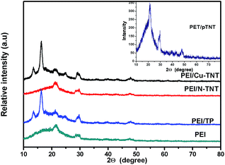 |
| | Fig. 3 XRD pattern of PEI and MMMs membranes. | |
3.3. Morphology of PEI and MMM membranes
The membrane surface and cross-section morphologies of the neat PEI and functionalized PEI membranes were investigated by scanning electron microscopy (SEM) analysis. The influence of nanoparticles addition onto the membrane surface is demonstrated in Fig. 4. The neat PEI membrane shows a denser top layer and the beneath part of membrane is tighter. It was observed that a change in cross-sectional morphology of membranes with the addition of nanomaterials. This may be due to the interlinking of hydrophilic TiO2 nanomaterials with hydrophobic PEI and which results in the fast exchange of solvent and non-solvent during phase inversion process and which in turn results in the increase of number of pores in functionalized PEI than neat PEI.39 Further, the fast exchange of solvent and non-solvent in the phase inversion process due to the hydrophilic nature of functionalized TNT and existing interactions between components in the casting solution and phase inversion kinetics.40,41
 |
| | Fig. 4 SEM images of top surface (left) and cross-section (right) of neat and MMM membranes. | |
It develops a broad finger like macro voids in the PEI/TP membrane than neat PEI membrane. In the third membrane, the finger-like macrovoids were gradually grown towards the bottom of the membrane and the shape of macrovoids became sponge-like porous structure when pTNT nanotubes were added into PEI membrane. The similar morphological behavior by addition of silver nanoparticles was observed by our earlier work.37 This may be due to decrease of interfacial stresses existed between polymer and layered H2Ti3O7 nanotubes, which were tensed by forming interfacial pores due to growth of the organic phase during the delayed demixing process.42 An extremely sponge like porous structure is observed in functionalized PEI membranes. Thus, morphology and surface properties of N-TNT and Cu-TNT nanomaterials were responsible for the large pore size and high water permeability of membranes. Celik et al.43 also reported similar morphological behavior.
3.4. Thermal stability of PEI and MMM membranes
The thermal stability characteristics of neat PEI and MMMs samples were evaluated by thermogravimetric analysis (TGA). and results are presented in Table 1. The TGA results of neat PEI and mixed matrix membranes with titania materials viz., TP, pTNT, N-TNT and Cu-TNT nanotubes were illustrated in Fig. 5. The temperature range of decomposition of the membrane and their corresponding weight% losses determine the thermal stability of the membranes. The first step of degradation corresponded to a slight but steep drop in residual weight% due to small weight loss observed between 97.4 and 234 °C for all the membranes due to evaporation of water and the residual NMP solvent (its boiling point is 202 °C).44 The major thermal degradation of membranes mainly occurs in the temperature range of 407 to 504 °C. However, the thermal degradation of membrane samples decreases with the addition of nanoparticles. Among the membranes PEI/Cu-TNT shows lesser degradation and higher thermal stability. It shows a 7.8% weight loss at a temperature range of 409 to 506 °C. Whereas, the neat PEI membrane shows higher thermal degradation with 13.9% weight loss. The other membranes of PEI with N-TNT, pTNT and TiO2 nanoparticles showed a weight% loss of 8.2%, 8.3% and 8.9% respectively. The TGA results also confirmed the presence of inorganic nanoparticles. During membrane fabrication, there is a chance for the nanoparticle to leach out at the time of phase inversion. The above results illustrates that the nanoparticles are still in the membrane and which enhances the thermal stability of mixed matrix membranes.45
Table 1 Thermal stability of nanomaterials functionalized PEI membranes
| Sample |
Decomposition stage |
| Temperature range (°C) |
Weight loss (%) |
| Neat PEI |
442 |
13.9 |
| PEI/TP |
445 |
8.9 |
| PEI/pTNT |
458 |
8.3 |
| PEI/N-TNT |
456 |
8.2 |
| PEI/Cu-TNT |
456 |
7.8 |
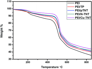 |
| | Fig. 5 Thermal stability of PEI and MMM membrane. | |
3.5. Hydrophilicity and water permeation of nanomaterials and functionalized PEI membranes
The hydrophilicity of membrane influences both water permeation and desalination performance. Higher contact angle corresponds to a hydrophobic surface whereas smaller contact value corresponds to hydrophilic surface of membranes.46 Fig. 6 displays the surface contact angles of PEI membranes blended with TNT and functionalized TNT nanomaterials. The contact angle of PEI membrane is 79.8° further these properties improved for different membranes are 75.5, 69.2, 63.5, 60.3° for PEI/TP, PEI/pTNT, PEI/N-TNT and PEI/Cu-TNT respectively. It is observed that the contact angle of nano metal oxides incorporated PEI membranes decreases, especially with TNT than TP. A large amount of surface hydroxyl groups in pTNT is ascribed due to nanotubular morphology and layered structure as well. Rajesh Kumar et al.29 reported that the contact angle of nascent polysulfone and PSf/chitosan membrane with 3.0% TiO2 NT are 73° and 58° respectively, that is contact angle of 20.5% decreased. Interestingly, in the present study PEI/Cu-TNT showed 20.1% decrease in contact angle without chitosan. Further decrease in contact angle of N-TNT is due to biphasic structure with oxygen defects in crystal structure. The Cu-TNT membrane showed lowest value among the nanotubes due to hydrophilic nature of copper species. Choi et al., reported47 that the hydrophilic functional groups into the surface of the carbon nanotubes (MWCNTs)/polysulfone blend membranes, thereby generating increased free volume and appropriate free volume cavity size. In general, the large amount of hydroxyl group on the metal oxide surface increases the hydrophilic character of the membrane that is hydrogen bonds between water and the membrane surface. In the case of nanomaterials functionalized membranes, the dimensions of membrane surface pores increase, more water is adsorbed by the membrane during the contact angle experiments. The above results are in-tune with earlier reports.
 |
| | Fig. 6 Contact angle of membranes. | |
Table 2 displays water permeation capacity and porosity of the membranes. Neat PEI membrane has the least water uptake of 62.3%. The water uptakes of the membrane increased to 70.5, 74.0, 79.0 and 82.2% for PEI membrane with nanoparticles TP, pTNT, N-TNT and Cu-TNT respectively. All the functionalized membranes showed increased in hydrophilic character with increase in porosity of the membranes. It reveals that, the membrane interconnectivity between the sub-layers increases with an increased number of surface pores of the skin layer, alternatively membrane hydraulic resistance decreases resulting in a higher water flux. The above results demonstrated the flux increases due to increased hydrophilicity, surface pore density and pore connectivity. An increase in water uptake with membrane functionalized with carbon nanotube and TNT has been reported.48
Table 2 Water uptake capacity and porosity of membranes
| Sl. no |
Membranes |
Water uptake capacity (%) |
Porosity (%) |
| 1 |
PEI |
62.3 |
14 |
| 2 |
PEI/TP |
70.5 |
21 |
| 3 |
PEI/pTNT |
74.0 |
25 |
| 4 |
PEI/N-TNT |
79.0 |
29 |
| 5 |
PEI/Cu-TNT |
82.2 |
33 |
3.6. Performance of mixed matrix membranes
3.6.1. Pure water flux. Fig. 7 represents pure water flux with time for different membranes. The membranes show a decline in water flux with respect to time when operated under high transmembrane pressure of 500 kPa and this loss in water flux is irreversible for membrane. Compaction is compression of the membrane structure under a high transmembrane pressure difference in which the walls of the pores became closer, denser and uniform resulting in reduction in pore size and flux during the compaction.49 After three hour operation the flux value reached to a steady state value which is higher for PEI membrane with Cu-TNT showed a 0.25 L m−2 h−1 steady state water flux. It was witnessed by water uptake study that the water uptake increases with nanoparticle doping and the same trend has been observed in the case of water flux too. Incorporation of nanoparticles into the membrane matrix results more hydrophilic properties, which facilitates the penetration of water into the membrane. As explained earlier for water uptake behavior, the same explanation will justify the water flux character of the membrane. The PEI/Cu-TNT membrane showed high initial and steady state water flux followed by PEI/N-TNT, PEI/pTNT, PEI/TP and neat PEI membranes. Incorporation of TNT nanomaterials into PEI membrane surface promoted the attachment of surface hydroxyl groups. The PEI surface and PEI network have strong interaction with water molecule, which led to attract water molecules by hydrophilicity of the membrane surface. This has beneficially contributed to the enhanced water permeability through the membrane.50 Zhao et al.51 demonstrated excessive TiO2 nanoparticles loadings decline hydrophilicity by decrease in specific surface area of aggregated nanoparticles. Hence, we chosen 0.5 wt% of TNT nanomaterial in PEI polymer matrix.
 |
| | Fig. 7 Pure water flux of membrane with time. | |
3.6.2. Permeate flux and rejection performance of salt solution. The permeate flux and rejection of salt solutions of K2SO4, NaCl and CaCl2 were studied with concentrations 500, 1000, 1500 and 2000 mg L−1 at the transmembrane pressure of 500 kPa. The effect of concentration on critical flux of salt solutions is listed in Tables 3–5. From tables, it is clear that flux is increasing with decrease in salt concentration for all the membranes. In addition, among the membranes, PEI/Cu-TNT showed higher permeates flux. The TiO2 nanotube in polymer matrix opened tube entrance, thus induced transport of ions through-hole TiO2 nanotube array membranes. In addition, MMMs prepared with N-TNT, pTNT and Cu-TNT are expected to enhance hydrophilicity in PEI polymer surface and matrix. The effect of novel functionalized nano-TiO2 loading electrocatalytic membrane for oily wastewater treatment reported.52 The electron–hole pairs were generated from TiO2 to promote the electron transfer, which was attributed to the special function of TiO2 membrane. They suggested that developed functional membranes would provide a brand-new prospect for water purification.
Table 3 Effect of concentration of K2SO4 solution on critical flux
| Concentration (mg L−1) |
Flux (L m−2 h−1) |
| PEI |
PEI/TP |
PEI/pTNT |
PEI/N-TNT |
PEI/Cu-TNT |
| 500 |
0.111 |
0.138 |
0.142 |
0.151 |
0.156 |
| 1000 |
0.101 |
0.108 |
0.115 |
0.12 |
0.127 |
| 1500 |
0.051 |
0.059 |
0.065 |
0.072 |
0.079 |
| 2000 |
0.019 |
0.025 |
0.034 |
0.041 |
0.049 |
Table 4 Effect of concentration of NaCl solution on critical flux
| Concentration (mg L−1) |
Flux (L m−2 h−1) |
| PEI |
PEI/TP |
PEI/pTNT |
PEI/N-TNT |
PEI/Cu-TNT |
| 500 |
0.111 |
0.119 |
0.126 |
0.134 |
0.14 |
| 1000 |
0.092 |
0.102 |
0.109 |
0.115 |
0.12 |
| 1500 |
0.036 |
0.042 |
0.048 |
0.054 |
0.059 |
| 2000 |
0.021 |
0.026 |
0.032 |
0.037 |
0.04 |
Table 5 Effect of concentration of CaCl2 solution on critical flux
| Concentration (mg L−1) |
Flux (L m−2 h−1) |
| PEI |
PEI/TP |
PEI/pTNT |
PEI/N-TNT |
PEI/Cu-TNT |
| 500 |
0.09 |
0.104 |
0.109 |
0.115 |
0.12 |
| 1000 |
0.070 |
0.079 |
0.086 |
0.093 |
0.099 |
| 1500 |
0.029 |
0.035 |
0.04 |
0.049 |
0.052 |
| 2000 |
— |
0.012 |
0.02 |
0.025 |
0.031 |
The tables above indicate that, for all the salts with lower concentration i.e., 500 ppm shows higher permeate flux and high salt concentration i.e., 2000 ppm shows lesser permeate flux. The reason for this can explain with the help of salt rejection, which is shown in Fig. 8–10. The rejection data also shows that low concentration of salt solution giving higher performance than high salt concentration. This means that actual salt concentration in permeate is lower and therefore the higher rejection. This is because, as concentration increases, the sorption of salt into the membrane increases and ability to reject salt decreases.53 In addition, PEI/Cu-TNT membrane shows more rejection for all salts followed by PEI/N-TNT, PEI/pTNT, PEI/TP and PEI membranes. The incorporation of hydrophilic TNT inside the membrane matrix encourages the formation of loss structure with a more open pore and porosity, and with enhanced hydrophilicity. Both effects facilitate solute transport through the membrane structure, thus increasing the permeate flux. The higher salt rejections of PEI/Cu-TNT suggest that void size of the polymer when swollen is more important.54
 |
| | Fig. 8 Rejection of potassium sulphate solution at different concentration. | |
 |
| | Fig. 9 Rejection of sodium chloride solution at different concentration. | |
 |
| | Fig. 10 Rejection of calcium chloride solution at different concentration. | |
Among the salts, potassium sulphate showed more flux and rejection followed by sodium chloride and calcium chloride. This can be explained with the help of ionic size and charge density. The higher rejection of K+ ion upto 80% for the membrane PEI/Cu-TNT is because of the higher ionic radius of the K+ ion (157 pm) than Na+ (116 pm) and Ca2+ ions (112 pm).55 The performance of TNT incorporated membrane depends on permeate flux and salt rejection. It is found that copper doped TNT shows improved performance. The rejection of potassium salt water increased around 15% over the neat PEI membrane at 500 ppm concentration. The enhanced rejection performance of Cu-TNT/PEI membrane is mainly ascribed due to smooth and hydrophilic wall of nano-tubes, which facilitated attraction and rapid movement of water molecules in polymer and nanotube chains. In addition, SO42− ion has net negative charge on their surface moiety. Furthermore, the higher radius of ions exhibit relatively better rejection, because these ions can restrictedly pass through PEI/Cu-TNT membrane, suggesting that the introduced very small organics through narrow the spacing within Cu functionalized membranes to form new nano networks. In case of membranes with the addition of pristine TNT and functionalized TNTs acquires higher negative charge on membrane surface. This negative charge and the membrane surface negative charge will highly repel and give better sulfate rejection. The K+ ion permeate through the negatively charged membrane only with the conjugate SO42− ion.56 In addition, the positive charge of copper doped TNT rejects the positively charged K+ ions. Hence, copper functionalized rejects more due to enhance ion selectivity. Similarly experiments with NaCl solution, PEI/Cu-TNT membranes holds higher rejection of up to 75%. The 21.70% of NaCl rejection at 1000 ppm was reported by Rajesh et al.57 using 1 wt% of TiO2 nanoparticles incorporated poly(amide-imide) asymmetric nanofiltration membranes. Interestingly, in our study, 3-fold (64%) higher rejection of similar concentration of NaCl solution was obtained using PEI/Cu-TNT membrane.
The results are displayed in Fig. 8–10. On contrary CaCl2 rejection was lowered up to 45%, it is mainly because of the small ionic radius of Ca2+ ions and less negative charge of Cl− ions. On whole, the membrane performance was ordered as a function of rejection as follows as PEI/Cu-TNT > PEI/N-TNT > PEI/pTNT > PEI/TP > PEI.
3.6.3. Protein adsorption. The effect of additive nanoparticles on membrane antifouling performance was also investigated through the static egg albumin adsorption test as shown in Fig. 11. It shows that change of egg albumin protein adsorbed onto the titanate nanotubes incorporated PEI membranes. Generally, the neat PEI membrane protein adsorption is higher because of its hydrophobic surface, so that the surface does not have significant ability to hinder the attachment of any kind of foulants. The nanoparticles incorporated membranes showed less egg albumin adsorption than a control membrane. The functionalized titanate nanotubes could be widened to attribute polymer onto a range of oxide type nanotubes. The affinity of PEI to functionalized titanate nanotubes in maintaining stable combinations of Cu-TNT, N-TNT and pTNT in aqueous solution egg albumin.57 Further, a study of the albumin adsorption on the membrane surface at different pH values was carried out. It can be seen that the highest adsorption occurred at pH 5 and shows a major aggregation of protein on the surface. The reason is that at pH 5 both protein and composite membranes are nonpolar; therefore the hydrophobic interaction causes the albumin to be more easily adsorbed on the surface.58 At lower pH, cationic species in solution resulted in chain relaxation leading to efficient solvent diffusion. At higher pH, there will be less amount of the protons in solution leads to small repulsion forces limits its flux performance. In addition, it could be possible that the albumin molecules may aggregate more easily because of hydrophobic interactions and reduced intramolecular and intermolecular electrostatic repulsion, which also leads to stronger adsorption.59,60
 |
| | Fig. 11 Effect of pH on protein adsorption of neat PEI and MMM membrane. | |
4. Conclusions
Hydrogen trititanate nanotubes were synthesized using simple method. It was functionalized with doping process using nitrogen or copper precursors. Mixed matrix membranes (PEI–titanate) was successfully prepared using titanate and functionalized titanate as additives. The nanotubular shape of pTNT was confirmed from TEM images. The crystal phase of both neat PEI and MMMs were analyzed using XRD pattern. The morphology analysis of MMMs showed macro voids formed after addition of titania based material compared to neat PEI membrane. The standard hydrophilic tests revealed that high hydrophilic nature of Cu-TNT among the membranes. The desalination experiments with different mono and divalent salt solution revealed that PEI/Cu-TNT showed high salt rejection besides enhanced flux and reduced fouling properties. In addition to that, the best membrane also exhibited sufficient stability against biofouling. The PEI/Cu-TNT displayed higher water uptake capacity, hydrophilicity, pure water flux and holds higher performance than neat and PEI/TP and pTNT respectively. Such enhanced salt rejection performance is ascribed due to increase in negative charges by addition of Cu-TNT to PEI, the resulting membrane showed improved charge densities and ions sieving performance.
Acknowledgements
Dr G. Arthanareeswaran is extremely thankful for facilities provided by University of Technology of Malaysia.
References
- A. Sotto, J. Kim, J. M. Arsuaga, G. del Rosario, A. Martinez, D. Nam, P. Luis and B. Van der Bruggen, J. Mater. Chem. A, 2014, 2, 7054 CAS.
- R. Saranya, G. Arthanareeswaran, S. Sakthivelu and P. Manohar, Ind. Eng. Chem. Res., 2012, 51, 4942 CrossRef CAS.
- J. M. Arsuaga, A. Sotto, G. Rosario, A. Martınez, S. Molina, S. B. Teli and J. Abajo, J. Membr. Sci., 2013, 428, 131 CrossRef PubMed.
- J. Kim and B. Van der Bruggen, Environ. Pollut., 2010, 158, 2335 CrossRef CAS PubMed.
- L. J. Zhu, L. P. Zhu, Y. F. Zhao, B. K. Zhu and Y. Y. Xu, J. Mater. Chem. A, 2014, 2, 15566 CAS.
- Y. S. Mok, A. Ananth and G. Arthanareeswaran, Polym. Bull., 2014, 7, 2851 Search PubMed.
- G. Arthanareeswaran and P. Thanikaivelan, Sep. Purif. Technol., 2010, 74, 230 CrossRef CAS PubMed.
- X. M. Wang, X. Y. Li and K. Shih, J. Membr. Sci., 2011, 368, 134 CrossRef CAS PubMed.
- K. D. Sitter, C. Dotremont, I. Genné and L. Stoops, J. Membr. Sci., 2014, 471, 168 CrossRef PubMed.
- Y. Lukka Thuyavan, N. Anantharaman, G. Arthanareeswaran and A. F. Ismail, Ind. Eng. Chem. Res., 2014, 53(28), 11355 CrossRef.
- S. Balta, A. Sotto, P. Luis, L. Benea, B. Van der Bruggen and J. Kim, J. Membr. Sci., 2012, 389, 155 CrossRef CAS PubMed.
- H. Dong, L. Zhao, L. Zhang, H. Chen, C. Gao and W. S. Winston Ho, J. Membr. Sci., 2015, 476, 373 CrossRef CAS PubMed.
- C. Kong, T. Shintani and T. Tsuru, New J. Chem., 2010, 34, 2101 RSC.
- C. Burda, X. Chen, R. Narayanan and M. A. El-Sayed, Chem. Rev., 2005, 105, 1025 CrossRef CAS PubMed.
- H. S. Kibombo, V. Balasanthiran, C. M. Wu, R. Peng and R. T. Koodali, Microporous Mesoporous Mater., 2014, 198, 1 CrossRef CAS PubMed.
- P. Roy, S. Berger and P. Schmuki, Angew. Chem., Int. Ed., 2011, 50, 2904 CrossRef CAS PubMed.
- M. V. Shankar and J. Ye, Catal. Commun., 2009, 11, 261 CrossRef CAS PubMed.
- D. Praveen Kumar, N. L. Reddy, M. M. Kumari, B. Srinivas, V. D. Kumari, V. Roddatis, O. Bondarchunk, M. Karthik, B. Nepplian and M. V. Shankar, Sol. Energy Mater. Sol. Cells, 2015, 136, 157 CrossRef CAS PubMed.
- J. Mansouri, S. Harrisson and V. Chen, J. Mater. Chem., 2010, 20, 4567 RSC.
- Q. Wang, Z. Wang, J. Zhang, J. Wang and Z. Wu, RSC Adv., 2014, 4, 43590 RSC.
- D. Wang and L. Liu, Chem. Mater., 2010, 22(24), 6656 CrossRef CAS.
- A. Fujishima, X. Zhang and D. A. Tryk, Surf. Sci. Rep., 2008, 63, 515 CrossRef CAS PubMed.
- G. Arrachart, I. Karatchevtseva, A. Heinemann, D. J. Cassidy and G. Triani, J. Mater. Chem., 2011, 21, 13040 RSC.
- J. Y. Wen and G. L. Wilkes, Chem. Mater., 1996, 8(8), 1667 CrossRef CAS.
- W. R. Bowen, S. Y. Cheng, T. A. Doneva and D. L. Oatley, J. Membr. Sci., 2005, 250, 1 CrossRef CAS PubMed.
- Y. Zhang and R. Wang, J. Membr. Sci., 2013, 443, 170 CrossRef CAS PubMed.
- A. Sotto, A. Boromand, S. Balta, J. Kim and B. Van der Bruggen, J. Mater. Chem., 2011, 21, 10311 RSC.
- S. P. Albu, A. Ghicov, J. M. Macak, R. Hahn and P. Schmuki, Nano Lett., 2007, 7, 1286 CrossRef CAS PubMed.
- R. Kumar, A. M. Isloor, A. F. Ismail, S. A. Rashid and A. A. Ahme, Desalination, 2013, 316, 76 CrossRef CAS PubMed.
- A. Sotto, A. Boromand, R. Zhang, P. Luis, J. M. Arsuaga, J. Kim and B. Van der Bruggen, J. Colloid Interface Sci., 2011, 363, 540 CrossRef CAS PubMed.
- Q. Yang, N. Adrus, F. Tomicki and M. Ulbricht, J. Mater. Chem., 2011, 21, 2783 RSC.
- R. Tedja, M. Lim, R. Amal and C. Marquis, ACS Nano, 2012, 6, 4083 CrossRef CAS PubMed.
- D. Praveen Kumar, M. V. Shankar, M. Mamatha Kumari, G. Sadanandan, B. Srinivas and V. Durga Kumari, Chem. Commun., 2013, 49, 9443 RSC.
- X. Sun and Y. Li, Chem.–Eur. J., 2003, 9, 2229 CrossRef CAS PubMed.
- B. Cojocaru, S. Neatu, V. I. Parvulescu, V. Somoghi, N. Petrea, G. Epure, M. Alvaro and H. Garcia, ChemSusChem, 2009, 2, 427 CrossRef CAS PubMed.
- R. Lakra, R. Saranya, Y. L. Thuyavan, S. Sugashini, K. M. Meera, S. Begum and G. Arthanareeswaran, Sep. Purif. Technol., 2013, 118, 853 CrossRef CAS PubMed.
- A. Ananth, G. Arthanareeswaran, A. F. Ismail, Y. S. Mok and T. Matsuura, Colloids Surf., A, 2014, 451, 151 CrossRef CAS PubMed.
- G. Arthanareeswaran and V. M. Starov, Desalination, 2011, 267, 57 CrossRef CAS PubMed.
- I. M. Wienk, R. M. Boom and M. A. M. Beerlage, J. Membr. Sci., 1996, 113, 361 CrossRef CAS.
- V. Vatanpour, S. S. Madaeni, R. Moradian, S. Zinadini and B. Astinchap, Sep. Purif. Technol., 2012, 90, 69 CrossRef CAS PubMed.
- V. Vatanpour, S. S. Madaeni, R. Moradian, S. Zinadini and B. Astinchap, J. Membr. Sci., 2011, 375, 284 CrossRef CAS PubMed.
- Y. Yanan, Z. Huixuan, W. Peng, Z. Qingzhu and L. Jun, J. Membr. Sci., 2007, 288, 231 CrossRef PubMed.
- E. Celik, H. Park, H. Choi and H. Choi, Water Res., 2011, 45, 274 CrossRef CAS PubMed.
- M. Asadullah, N. S. Rasid, S. A. Syed, A. Kadir and A. Azdarpour, Biomass Bioenergy, 2013, 59, 316 CrossRef CAS PubMed.
- H. Bessbousse, T. Rhlalou, J. F. Verchère and L. Lebrun, J. Membr. Sci., 2008, 307, 249 CrossRef CAS PubMed.
- A. Pagidi, R. Saranya, G. Arthanareeswaran, A. F. Ismail and T. Matsuura, Desalination, 2014, 344, 280 CrossRef CAS PubMed.
- J. H. Choi, J. Jegal and W. N. Kim, J. Membr. Sci., 2006, 284, 406 CrossRef CAS PubMed.
- E. S. Kim, G. Hwang, M. G. El-Din and Y. Liu, J. Membr. Sci., 2012, 394–395, 37 CrossRef CAS PubMed.
- S. Chakraborty, M. K. Purkait, S. Dasgupta, S. De and J. K. Basu, Sep. Purif. Technol., 2003, 31, 141 CrossRef CAS.
- P. S. Goh, B. C. Ng, W. J. Lau and A. F. Ismail, Sep. Purif. Rev., 2015, 44, 216 CrossRef CAS.
- S. Zhao, P. Wang, C. Wang, X. Sun and L. Zhang, Desalination, 2012, 299, 35 CrossRef CAS PubMed.
- Y. Yang, H. Wang, J. Li, B. He, T. Wang and S. Lia, Environ. Sci. Technol., 2012, 46(12), 6815 CrossRef CAS PubMed.
- H. Zhua, A. Szymczyka and B. Balanneca, J. Membr. Sci., 2011, 379, 215 CrossRef PubMed.
- R. Lo, A. Bhattacharya and B. Ganguly, J. Membr. Sci., 2013, 436, 90 CrossRef CAS PubMed.
- H. M. Krieg, S. J. Modiser, K. Kiezer and H. W. J. P. Neomagus, Desalination, 2004, 171, 205 CrossRef PubMed.
- S. B. Teli, S. Molina, A. Sotto, E. G. Calvo and J. de Abajob, Ind. Eng. Chem. Res., 2013, 52, 9470 CrossRef CAS.
- S. Rajesh, A. F. Ismail and D. Mohan, RSC Adv., 2012, 2, 6854 RSC.
- R. Tedja, A. H. Soeriyadi, M. R. Whittaker, M. Lim, C. Marquis, C. Boyer, T. P. Davis and R. Amal, Polym. Chem., 2012, 3, 2743 RSC.
- J. Dasgupta, S. Chakraborty, J. Sikder, R. Kumar, D. Pal, S. Curcio and E. Drioli, Sep. Purif. Technol., 2014, 133, 55 CrossRef CAS PubMed.
- R. S. Hebbar, A. M. Isloor and A. F. Ismail, RSC Adv., 2014, 4, 55773 RSC.
|
| This journal is © The Royal Society of Chemistry 2015 |
Click here to see how this site uses Cookies. View our privacy policy here. 


