Enhanced power factor within graphene hybridized carbon aerogels

Zhouyue Leia, Yugang Yana, Jing Fengb, Jinrong Wu*a, Guangsu Huang*a, Xiaodong Lia, Wang Xinga and Lijuan Zhao*c
aState Key Laboratory of Polymer Material Engineering, College of Polymer Science and Engineering, Sichuan University, Chengdu 610065, P. R. China. E-mail: wujinrong@scu.edu.cn
bSchool of Engineering and Applied Sciences, Harvard University, Cambridge, MA 02138, USA
cCollege of Chemistry and Material Science, Sichuan Normal University, Chengdu, 610068, P. R. China

Received 20th February 2015 , Accepted 4th March 2015

First published on 4th March 2015


Abstract

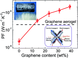
We demonstrate that the electrical conductivity and Seebeck coefficient can be simultaneously enhanced in graphene hybridized carbon aerogels (GHCAs). To prepare the GHCAs, graphene is introduced into the pyrolyzed resorcinol-formaldehyde (RF) aerogel, which significantly improves the electrical conductivity. At the same time, large interfaces between graphene sheets and pyrolyzed RF resin generate an energy filtering effect, which increases the Seebeck coefficient. This strategy promises a power factor which is two orders of magnitude higher than that of pure pyrolyzed RF aerogel. Moreover, the tenuous solid skeleton and highly open-cell foam structure of the GHCAs lead to ultra low thermal conductivity (0.06 W m−1 K−1) and apparent density (31 kg m−3). This may enable the development of a novel category of ultra-lightweight energy-conversion materials with thermal insulation capability.
Introduction

The economic modern world relies largely on fossil energy, which however is not renewable. Most countries now are seeking new energy conversion materials. One promising candidate is thermoelectric (TE) materials which convert waste heat into electricity. The commercially available inorganic TE materials have limited applications due to their instability, high cost, and potential toxicity and the scarcity of some key elements. This motivates us to seek organic materials as TE materials. Conducting polymers have the advantages of low thermal conductivity, low cost, low weight and convenience of processing, thus they are considered to be a potential category of TE materials.1,2 Nevertheless, increasing the electrical conductivity (σ) of conducting polymers by doping generally results in a tremendous decrease in the Seebeck coefficient (S). This tradeoff gives rise to little increase in the power factor (S2σ), which imposes a great challenge to enhancement of TE performance of organic materials.2 A recent breakthrough was achieved by controlling the doping and oxidation level of poly (3, 4-ethylenedioxythiophene) (PEDOT), generating a ZT value comparable to that of some traditional inorganic materials.3–6 Alternatively, compounding of organic or inorganic materials is another potential way to improve the power factor.7–11 The electrical conductivity and the thermal conductivity can be decoupled within a segregated-network structure of carbon nanotube/polymer composites.12–15 A power factor near to traditional TE materials was generated through further tuning the segregated-network with conducting and semiconducting stabilizers.12–15 Some other works used graphene to construct hierarchical nanostructures with PEDOT, which showed significant improvement in the power factor compared with single components.16–18 These researches have suggested the prominent potential of using carbon-based materials as TE materials.

Herein, we consider that conducting carbon aerogels can be an alternative type of promising energy-conversion materials due to their unique properties: (1) the tenuous solid skeleton and highly open-cell foam structure strongly impede phonon transport, thus the thermal conductivity can be as low as 0.012 W m−1 K−1 reported by Lu et al.;19 (2) the 3D network structure provides multiple paths for rapid transport of electrons, resulting in a electrical conductivity up to 2000 S m−1 in the works of Lu et al.20 and Gao et al.;21 (3) there are many junctions and interfaces in the aerogels, which may have the effect of electron filtering,22–26 so that the Seebeck coefficient and the electrical conductivity can be decoupled and simultaneously improved. There are two additional advantages of conducting aerogels: (1) aerogels have an extremely low density (∼40 kg m−3) compared to traditional TE materials such as, Bi2Te3 (∼7860 kg m−3),12 therefore, if Bi2Te3 is replaced by an aerogel with similar TE performance, the power density could be approximately 200 times higher; and (2) aerogels are simpler to fabricate, scalable and low-cost.

To verify the hypothesis proposed above, pyrolyzed resorcinol-formaldehyde (RF) aerogel is used as the control, graphene is introduced to prepare graphene hybridized carbon aerogels (GHCAs). The reason for introduction of graphene is that graphene has high electron mobility and long electron mean free paths,27,28 and it is convenient to assemble graphene into the 3D network structure of aerogels.21,29 Following the protocol of Worsley et al.,29 resorcinol (R) and formaldehyde (F) are sol–gel polymerized in the aqueous graphene oxide (GO) suspension to form GO-RF hydrogels. Instead of supercritical CO2 drying, we use freeze drying with lower cost and environmental impact to prepare GO-RF aerogels, which are subsequently pyrolyzed to generated the graphene hybridized carbon aerogels (GHCAs), as shown in Fig. 1. During the pyrolysis process, the carbonized RF forms conductive junctions between the high-temperature reduced graphene layers, thus facilitates the carrier transportation of GHCAs. The pyrolysis process also generates large interfaces between graphene and pyrolyzed RF, which may have energy filtering and phonon scattering effects, as shown in the left panel of Fig. 1. For comparison, a pure pyrolyzed RF aerogel and a pure graphene aerogel are also prepared. We find that the electrical conductivity and the Seebeck coefficient of the GHCAs both exceed the values obtained with either pure pyrolyzed RF aerogel or pure graphene aerogel. As a result, the power factor shows two orders of magnitude improvement compared to the control. Moreover, the GHCAs have ultra low thermal conductivity and apparent density, which may enable the development of a new category of ultra lightweight TE materials with thermal insulation capability.


image file: c5ra03198b-f1.tif
Fig. 1 The synthesis route of the GHCAs. Sol–gel polymerization of RF in aqueous GO suspension generates GO-RF hydrogel, which is then freezing dried and pyrolyzed to obtain GHCAs. The junctions in GHCAs may have energy filtering effect which contributes to the enhanced Seebeck coefficient, and phonon scattering effect which results in suppressed thermal conductivity.

Results and discussion

As shown in the XRD patterns of Fig. 2(a), graphite has characteristic peaks at 2θ of 26.4° and 44.4°, corresponding to C (002) and C (101), respectively. The presence of the stacking-related C (002) and C (101) diffraction peaks in the pyrolyzed RF aerogel indicates the partially graphitized carbon structure.30 With addition of 31 wt% graphene (graphene content in the GHCAs is calculated by the TGA results, as seen in Fig. S1 in ESI), the GHCA shows no evident peak indicating an amorphous structure of the pyrolyzed RF resin and the well exfoliation of the graphene sheets. This superior exfoliation of the graphene sheets and the disordered structure are even better than those of the pure graphene aerogel, since the diffraction pattern for the pure graphene aerogel still shows evident C (002) and C (101) peaks. XPS analysis indicates that the atomic ratio of C[thin space (1/6-em)]:[thin space (1/6-em)]O in the pyrolyzed GHCA with 31 wt% graphene is 98.5/1.5, much higher than 79.4/20.6 in the corresponding un-pyrolyzed precursor, i.e., the GO-RF aerogel. Fig. 2(b) shows that the C–O, C[double bond, length as m-dash]O components are significantly reduced in the GHCA after pyrolysis at 1050 °C. Raman spectra in Fig. 2(c) demonstrate an increase in the intensity ratio of D band to G band after pyrolysis, due to the edge defects of newly-formed small graphitic domains on the graphene sheets.31,32
image file: c5ra03198b-f2.tif
Fig. 2 Structural characterizations of the aerogels. (a) XRD patterns of graphite, pure graphene aerogel, pure pyrolyzed RF aerogel and GHCA with 31 wt% graphene; (b) C1s XPS spectra of the GO-RF aerogel and GHCA with 31 wt% graphene; and (c) Raman spectra of the GO aerogel, GO-RF aerogel and GHCA with 31 wt% graphene.

The microstructures of the GO-RF aerogels and the GHCAs are examined with SEM. As shown in Fig. 3(a)–(c), the GO and RF co-assembly to form wrinkled paper-like sheets, which are tightly connected to obtain a 3D network with porous structure in the GO-RF aerogels. The pyrolysis process generates some defects on the sheets, but the connections between the sheets still remain intact and tight, as indicated in Fig. 3(d)–(f). To further elucidate the advantage of GHCAs and the mutual interaction between the graphene sheets and the pyrolytic RF resin, the morphology of the pure graphene aerogel is also illustrated in Fig. 3(g)–(i). It can be seen that the pure graphene aerogel also has a porous structure similar with that of the GHCAs. However, two distinct differences between them should be noticed: (1) the sheets in the GHCAs are much thicker than those in the pure graphene aerogel, due to the fact that the carbon atoms generated by the pyrolyzed RF resin are absorbed onto the surfaces of the graphene sheets; (2) the pore size of the GHCAs is much smaller than that of the pure graphene aerogel, which can be ascribed to the assistance of RF resin in forming the compact chemical bonded networks. Thus the GHCAs have a more effective network structure in which the graphene sheets are tightly connected at the junctions. In contrast, the graphene sheets are loosely connected at the junctions in the graphene aerogel. This unique feature of the GHCAs leads to an improvement in the carrier mobility and generate a lot of interfaces between the graphene sheets and the pyrolytic RF resin.


image file: c5ra03198b-f3.tif
Fig. 3 SEM images of (a–c) the GO-RF aerogel with 20 wt% of GO, (d–f) and its pyrolyzed GHCAs, and (g–i) the chemically-reduced graphene aerogel.

Light weight and large specific surface area are two typical features of aerogels. As shown in Fig. 4, the pyrolyzed RF aerogel has an apparent density (ρ) of 300 kg m−3 and a BET surface area of 182 m2 g−1, which are lower than the corresponding values in aerogels prepared by supercritical drying.33 Fortunately, with incorporation of 15 wt% of graphene in the GHCA, the apparent density decreases dramatically to 49 kg m−3, while the BET surface area increases significantly to 528 m2 g−1. Increasing the graphene content in the GHCAs leads to a further reduction in the apparent density and a further increase in the BET surface area. In the GHCA with 31 wt% graphene, the apparent density and the BET surface area are 31 kg m−3 and 715 m2 g−1, respectively. But further addition of graphene causes a slightly higher apparent density and a decreased BET surface area. A probable reason is that at higher GO weight fraction, the RF cannot effectively separate the GO layers and is less efficient in assisting to construct the 3D network of the aerogels. Nevertheless, these results are comparable with those of the carbon aerogel prepared through supercritical-CO2-drying, which has a density around 10 kg m−3 and a BET surface area of 584 m2 g−1 in the work of Worsley et al.29 It indicates that the low-cost method employed in this work is effective and convenient for preparing aerogel materials.


image file: c5ra03198b-f4.tif
Fig. 4 Apparent density and BET surface area of GHCAs with different weight fractions of graphene.

The electrical conductivity of the pure carbonized RF aerogel is 119 S m−1, as shown in Fig. 5(a). Addition of graphene effectively improves the electrical conductivity of the GHCAs to 200–400 S m−1, which is also higher than that of the pure graphene aerogel with physical cross-links alone (∼100 S m−1, measured in this work). The reason for this improvement is that the pyrolyzed RF and graphene sheets form the intact 3D network with tight junctions (as revealed by SEM), which is more effective for electron transport than the physically-bonded networks.29 At still higher graphene contents, e.g., 39 wt%, the electrical conductivity of the HCA exhibits a slight decrease. A similar phenomenon was also found by Worsley et al. in a previous report.29 The probable reason is that it is difficult to fully exfoliate the GO layers in the initial reaction mixture at higher GO/RF ratios, which leads to the aggregation of the GO layers and thus introduces inhomogeneity to the network structure of the GHCAs. This inhomogeneity may have a negative effect on the integrity of the network. Therefore, when the graphene content exceeds 39 wt%, the GHCAs cannot keep good shape stability.


image file: c5ra03198b-f5.tif
Fig. 5 (a) Electrical conductivity, (b) Seebeck coefficient, and (c) power factor and (d) thermal conductivity of the GHCAs with different weight fractions of graphene at room temperature.

The Seebeck coefficient as a function of graphene content is shown in Fig. 5(b). It is noteworthy that the Seebeck coefficient of the GHCAs increases remarkably upon addition of graphene. Specifically, the pure pyrolyzed RF aerogel has a low Seebeck coefficient of 14 μV K−1, while a significant enhancement to 82 μV K−1 is attained with the addition of 39 wt% graphene. This value is also larger than the Seebeck coefficient of single-layer graphene (about 30.5 μV K−1 at 300 K)34 and that of the pure graphene aerogel (about 45 μV K−1 at 300 K, measured in this work). Thus, the GHCAs consisting of hybridized graphene sheets with carbonized RF resin are more efficient at converting the temperature gradient into voltage than each component alone. This effect probably originates from an energy-filtering effect.22–26 As the work function of graphene reduced from GO (∼4.2 eV (ref. 35)) is smaller than that of pyrolytic carbon (∼4.6 eV (ref. 36)), charge carriers cannot readily transfer from graphene to carbonized RF resin in the presence of the potential barrier resulting from the work-function differences. This allows carriers with higher energy to pass through while scatters the low-energy ones, thereby increases the mean carrier energy in the flow, i.e., the Seebeck coefficient.23,25,26 The higher weight fraction of graphene generates more interfaces, which results in substantial energy filtering and gives rise to the higher Seebeck coefficient of the GHCAs.

The simultaneous increase in the electrical conductivity and Seebeck coefficient significantly enhances the power factor of the GHCAs, as shown in Fig. 5(c). Incorporation of 39 wt% graphene leads to two orders of magnitude improvement in the power factor value of the GHCA compared with that of the pure carbonized RF aerogel. This value is also one order of magnitude higher than that of pure graphene aerogel (measured in this work, as shown by the grey dashed lines in Fig. 5(c)).

The strategy of constructing the 3D network with porous structure promises the GHCAs with ultra low thermal conductivity, as shown in Fig. 5(d). The thermal conductivity of the pure pyrolyzed RF aerogel is 0.09 W m−1 K−1, which is consistent with the previously reported value.20 Upon addition of 15 wt% graphene, the thermal conductivity decreases to ∼0.06 W m−1 K−1, accompanied by the apparent reduction in the density from 305 kg m−3 to ∼40 kg m−3. This suggests that the decrease in the density can further leads to lower thermal conductivity. The thermal conductivity of aerogel materials is the sum of solid, gaseous, radiative, and convective thermal conductivities.37,38 Among them, the convective thermal conductivity is negligible, when convection of the gas trapped in the materials with a pore size less than 1 mm at ambient pressure is completely suppressed.37 The thermal conduction through the solid in aerogels is limited by the extremely small connections between the thin sheets, and the phonon conductivity in the GHCAs is also reduced because of phonon scattering induced by the interfaces and graphene defects. Similarly, the gaseous conduction is suppressed because the pore size of aerogels is comparable to the mean-free-path size for gas molecular collision.37,38 The radiative part of thermal conductivity in aerogels is proportional to the mean free path for phonons.39 Since the presence of many interfaces between graphene layers and carbonized RF resin generates strong phonon scattering effects, it leads to a decreased mean free path for phonons and a very low radiative thermal conductivity. Therefore, the combined effect of these factors leads to the ultra-low thermal conductivity of GHCAs, which makes them viable candidates for TE materials.

The reduced thermal conductivity, and the enhanced Seebeck coefficient and electrical conductivity generate a highest ZT value of 1.02 × 10⁻² at room temperature upon addition of 39 wt% graphene. This ZT value is about 2 orders of magnitude higher than that of either pure carbonized RF aerogel or pure graphene aerogel, and 3 orders of magnitude higher than that of single-layer graphene (calculated according to the literature reported values of TE properties of graphene: κ = 5000 W m−1 K−1,40 α = 30.5 μV K−1,34 σ = 6 × 10⁵ S m−1,27,41 ZT = 3.35 × 10⁻⁵). This value is also more than 2 orders of magnitude higher than that of graphene/polyaniline nanocomposites,42,43 and comparable to that of more expensive graphene/PEDOT nanocomposites.16–18 Although the ZT value of 0.01 is too low for practical application, this work provides a new approach for TE materials and it is possible to achieve greater improvement if nanostructured inorganic semiconductor TE materials are introduced into the conducting aerogels.

Conclusions

In summary, GHCAs are prepared by introducing graphene into pyrolyzed RF aerogels. The co-assembly of graphene and pyrolyzed RF generates a compact 3D network with tight junctions, which facilitates electron transportation and thus improves the electrical conductively. Meantime, the Seebeck coefficient is significantly enhanced, due to the energy filtering effect generated by the large interfaces between graphene sheets and pyrolyzed RF. The simultaneously enhanced electrical conductivity and Seebeck coefficient promise a power factor that is two orders of magnitude than that of the pure pyrolyzed RF aerogel. Moreover, the GHCAs have ultra low thermal conductivity and apparent density, thus may be eligible for light-weight energy conversion applications with heat insulation ability.

Experimental

Materials

Natural graphite flakes (40 μm) were purchased from Qingdao Ruisheng Company (China), formaldehyde (38.5%) was provided by Chengdu Jinshan Company (China), resorcinol and sodium carbonate were purchased from Tianjin Bodi Company (China), and other chemicals were obtained from Chengdu Kelong Company (China).

Preparation of GO-RF aerogels

Graphene oxide was prepared through a modified Hummers method,44,45 as shown in the ESI. To prepare GO-RF aerogels, 0.4139 g of resorcinol (R), 0.6255 g of formaldehyde (F, 38.5%), and 0.0020 g of sodium carbonate catalyst (C) were added into 6 g of aqueous GO suspensions with different concentrations. The molar ratio of R[thin space (1/6-em)]:[thin space (1/6-em)]F was 1[thin space (1/6-em)]:[thin space (1/6-em)]2, the molar ratio of R[thin space (1/6-em)]:[thin space (1/6-em)]C was 200[thin space (1/6-em)]:[thin space (1/6-em)]1, the RF in the starting mixture has a concentration of 9 wt%, and the concentrations of GO relative to the total weight of GO and RF included 0 wt%, 9 wt%, 15 wt%, 20 wt% and 27 wt%. The mixtures were cured in glass moulds at 65 °C for 48 hours. The resulting gels were quenched with liquid nitrogen and then freeze dried for 24 hours to obtain the GO-RF aerogels.

Pyrolysis to obtain graphene hybridized carbon aerogels

The GO-RF aerogels were pyrolyzed at a heating rate of 1 °C min−1 to 1050 °C under vacuum environment and then cooled down at a rate of 3 °C min−1 to room temperature, which generated the GHCAs. A pure carbonized RF aerogel was also prepared with the same procedure.

Preparation of pure graphene aerogel

An aqueous suspension with 1.86 wt% GO was quenched with liquid nitrogen and then freeze dried. The resulting GO aerogel was subjected to chemical reduction using hydroiodic acid for 8 hours at 90 °C to prepare the pure graphene aerogel.

Characterizations

Atomic force microscope measurement was carried out using a Nanoscope multimode V8 to characterize the morphology and the thickness of GO layers, as shown in Fig. S2 of ESI. Thermogravimetric analysis (TGA) was performed using a Netzsch TG209F1 analyzer from room temperature to 988 °C at heating rate of 10 °C min−1 with N2 protection, and the weight losses of GO aerogel and RF aerogel in Fig. S1 of ESI were used to calculate the graphene content (wt%) in the GHCAs. Apparent density of each carbon aerogel was determined from its physical dimensions and weight. Nitrogen sorption measurements were performed with a TriStar Micromeritics to obtain the Brunauer–Emmett–Teller (BET) specific surface area. The microstructures of the carbon aerogels were examined by a scanning electron microscopy (SEM: Quanta250) after coating the samples with gold nanoparticles. X-ray diffraction (XRD) patterns were obtained with a Philips X'Pert Graphics & Identify with Ni-filtered CuKα radiation (k = 0.154 nm) at a generator voltage of 40 kV and a tube current of 30 mA. Scanning was at a speed of 2.4 °C min−1, from 5 to 50° 2θ. X-Ray photoelectron spectroscopy (XPS) spectra were acquired with a EURO EA3000 spectrometer. The elemental compositions were determined from peak area ratios after correction of the sensitivity factor for each element. Raman spectra were recorded on a LABRAM HR800 confocal micro-Raman spectrometer using a 532 nm ND:YAG laser.

The thermal conductivity (κ) of the carbon aerogels was measured by a transient plane source method using a Hot Disk 2500-OT. The electrical conductivity (σ) of the carbon aerogels was determined via a four-probe method on a RTS-8 ohmmeter (Guangzhou Four-probe Technology Company). The current transmitted through the sample during the measurement was 100 mA. The Seebeck coefficient (α) was measured by placing the sample between two copper cylinders attached to two Peltier modules, one for heating and another for cooling. They generated the temperature gradient across the sample and meanwhile induced thermal voltage. The temperature gradient (ΔT) was accurately measured through two mini thermocouples, the resulting thermally induced voltage (ΔV) was measured by the voltage probes, and α was calculated by α = ΔVT.

Acknowledgements

The authors would like to acknowledge the financial support by the National Natural Science Foundation of China (Grant no.: 51303116) and Sichuan University. We also appreciate Helen Wu at Harvard University for polishing the English.

References

  1. A. B. Kaiser, Phys. Rev. B: Condens. Matter Mater. Phys., 1989, 40, 2806–2813 CrossRef.
  2. Y. Du, S. Z. Shen, K. F. Cai and P. S. Casey, Prog. Polym. Sci., 2012, 37, 820–841 CrossRef CAS PubMed.
  3. O. Bubnova, Z. U. Khan, A. Malti, S. Braun, M. Fahlman, M. Berggren and X. Crispin, Nat. Mater., 2011, 10, 429–433 CrossRef CAS PubMed.
  4. O. Bubnova, M. Berggren and X. Crispin, J. Am. Chem. Soc., 2012, 134, 16456–16459 CrossRef CAS PubMed.
  5. G. H. Kim, L. Shao, K. J. Zhang and K. P. Pipe, Nat. Mater., 2013, 12, 719–723 CrossRef CAS PubMed.
  6. T. Park, C. Park, B. Kim, H. Shin and E. Kim, Energy Environ. Sci., 2013, 6, 788 CAS.
  7. Q. Wang, Q. Yao, J. Chang and L. Chen, J. Mater. Chem., 2012, 22, 17612–17618 RSC.
  8. B. Abad, I. Alda, P. Diaz-Chao, H. Kawakami, A. Almarza, D. Amantia, D. Gutierrez, L. Aubouy and M. Martin-Gonzalez, J. Mater. Chem. A, 2013, 1, 10450–10457 CAS.
  9. J. S. Carrete, N. Mingo, G. Tian, H. Ågren, A. Baev and P. N. Prasad, J. Phys. Chem. C, 2012, 116, 10881–10886 CAS.
  10. Y. Du, K. F. Cai, S. Chen, P. Cizek and T. Lin, ACS Appl. Mater. Interfaces, 2014, 6, 5735–5743 CAS.
  11. J. Chen, X. Gui, Z. Wang, Z. Li, R. Xiang, K. Wang, D. Wu, X. Xia, Y. Zhou, Q. Wang, Z. Tang and L. Chen, ACS Appl. Mater. Interfaces, 2012, 4, 81–86 CAS.
  12. C. Yu, Y. S. Kim, D. Kim and J. C. Grunlan, Nano Lett., 2008, 8, 4428–4432 CrossRef CAS PubMed.
  13. D. Kim, Y. Kim, K. Choi, J. C. Grunlan and C. Yu, ACS Nano, 2009, 4, 513–523 CrossRef PubMed.
  14. C. Yu, K. Choi, L. Yin and J. C. Grunlan, ACS Nano, 2011, 5, 7885–7892 CrossRef CAS PubMed.
  15. G. P. Moriarty, K. Briggs, B. Stevens, C. Yu and J. C. Grunlan, Energy Technol., 2013, 1, 265–272 CrossRef CAS.
  16. D. Yoo, J. Kim and J. H. Kim, Nano Res., 2014, 7, 717–730 CrossRef CAS.
  17. K. Zhang, Y. Zhang and S. Wang, Sci. Rep., 2013, 3 Search PubMed.
  18. G. H. Kim, D. H. Hwang and S. I. Woo, Phys. Chem. Chem. Phys., 2012, 14, 3530–3536 RSC.
  19. X. Lu, M. C. Arduini-Schuster, J. Kuhn, O. Nilsson, J. Fricke and R. W. Pekala, Science, 1992, 255, 971–972 CAS.
  20. X. P. Lu, O. Nilsson, J. Fricke and R. W. Pekala, J. Appl. Phys., 1993, 73, 581–584 CrossRef CAS PubMed.
  21. Z. Xu, Y. Zhang, P. G. Li and C. Gao, ACS Nano, 2012, 6, 7103–7113 CrossRef CAS PubMed.
  22. J. M. O. Zide, D. Vashaee, Z. X. Bian, G. Zeng, J. E. Bowers, A. Shakouri and A. C. Gossard, Phys. Rev. B: Condens. Matter Mater. Phys., 2006, 74, 205335 CrossRef.
  23. S. V. Faleev and F. Léonard, Phys. Rev. B: Condens. Matter Mater. Phys., 2008, 77, 214304 CrossRef.
  24. A. J. Minnich, M. S. Dresselhaus, Z. F. Ren and G. Chen, Energy Environ. Sci., 2009, 2, 466 CAS.
  25. C. Z. Meng, C. H. Liu and S. S. Fan, Adv. Mater., 2010, 22, 535–539 CrossRef CAS PubMed.
  26. M. He, J. Ge, Z. Q. Lin, X. H. Feng, X. W. Wang, H. B. Lu, Y. L. Yang and F. Qiu, Energy Environ. Sci., 2012, 5, 8351–8358 CAS.
  27. X. Du, I. Skachko, A. Barker and E. Y. Andrei, Nat. Nanotechnol., 2008, 3, 491–495 CrossRef CAS PubMed.
  28. D. Sim, D. Liu, X. Dong, N. Xiao, S. Li, Y. Zhao, L.-J. Li, Q. Yan and H. H. Hng, J. Phys. Chem. C, 2011, 115, 1780–1785 CAS.
  29. M. A. Worsley, P. J. Pauzauskie, T. Y. Olson, J. Biener, J. H. Satcher and T. F. Baumann, J. Am. Chem. Soc., 2010, 132, 14067–14069 CrossRef CAS PubMed.
  30. J. Li, X. Wang, Q. Huang, S. Gamboa and P. J. Sebastian, J. Power Sources, 2006, 158, 784–788 CrossRef CAS PubMed.
  31. A. C. Ferrari, J. C. Meyer, V. Scardaci, C. Casiraghi, M. Lazzeri, F. Mauri, S. Piscanec, D. Jiang, K. S. Novoselov, S. Roth and A. K. Geim, Phys. Rev. Lett., 2006, 97, 187401 CrossRef CAS.
  32. D. Graf, F. Molitor, K. Ensslin, C. Stampfer, A. Jungen, C. Hierold and L. Wirtz, Nano Lett., 2007, 7, 238–242 CrossRef CAS PubMed.
  33. S. A. Al-Muhtaseb and J. A. Ritter, Adv. Mater., 2003, 15, 101–114 CrossRef CAS.
  34. X. M. Li, J. Yin, J. X. Zhou, Q. Wang and W. L. Guo, Appl. Phys. Lett., 2012, 100, 183108 CrossRef PubMed.
  35. A. Benayad, H. J. Shin, H. K. Park, S. M. Yoon, K. K. Kim, M. H. Jin, H. K. Jeong, J. C. Lee, J. Y. Choi and Y. H. Lee, Chem. Phys. Lett., 2009, 475, 91–95 CrossRef CAS PubMed.
  36. S. Suzuki, C. Bower, Y. Watanabe and O. Zhou, Appl. Phys. Lett., 2000, 76, 4007–4009 CrossRef CAS PubMed.
  37. L. W. Hrubesh and R. W. Pekala, J. Mater. Res., 1994, 9, 731–738 CrossRef CAS.
  38. O. J. Lee, K. H. Lee, T. Jin Yim, S. Young Kim and K. P. Yoo, J. Non-Cryst. Solids, 2002, 298, 287–292 CrossRef CAS.
  39. R. Caps and J. Fricke, Aerogels, Springer-Verlag, Heidelberg, Germany, 1986 Search PubMed.
  40. A. A. Balandin, S. Ghosh, W. Bao, I. Calizo, D. Teweldebrhan, F. Miao and C. N. Lau, Nano Lett., 2008, 8, 902–907 CrossRef CAS PubMed.
  41. H. Kim, A. A. Abdala and C. W. Macosko, Macromolecules, 2010, 43, 6515–6530 CrossRef CAS.
  42. J. L. Xiang and L. T. Drzal, Polymer, 2012, 53, 4202–4210 CrossRef CAS PubMed.
  43. Y. Lu, Y. Song and F. P. Wang, Mater. Chem. Phys., 2013, 138, 238–244 CrossRef CAS PubMed.
  44. W. S. Hummers and R. E. Offeman, J. Am. Chem. Soc., 1958, 80, 1339–1339 CrossRef CAS.
  45. S. Stankovich, D. A. Dikin, G. H. B. Dommett, K. M. Kohlhaas, E. J. Zimney, E. A. Stach, R. D. Piner, S. T. Nguyen and R. S. Ruoff, Nature, 2006, 442, 282–286 CrossRef CAS PubMed.

Footnote

Electronic supplementary information (ESI) available: Enhanced power factor within graphene hybridized carbon aerogels. See DOI: 10.1039/c5ra03198b

This journal is © The Royal Society of Chemistry 2015
Click here to see how this site uses Cookies. View our privacy policy here.