Anisotropic growth of Ni3(BO3)2 nanowhiskers on nickel substrates and its application in the fabrication of superhydrophilic surfaces†
Yifeng Wang,
Jicai Feng,
Bin Feng,
Xiaoguo Song and
Jian Cao*
State Key Laboratory of Advanced Welding and Joining, Harbin Institute of Technology, Harbin 150001, China. E-mail: cao_jian@hit.edu.cn; Fax: +86-0451-86418146; Tel: +86-0451-86418146
First published on 17th March 2015
Abstract
One-dimensional (1D) single-crystalline nickel borate [Ni3(BO3)2] nanowhiskers were successfully grown on Ni substrates using the facile molten-salt method in air with MnO2 as the agent. The products were characterized via X-ray diffraction, scanning electron microscopy, and transmission electron microscopy. The Ni3(BO3)2 nanowhiskers that were synthesized at 950 °C, with diameters ranging from 120 to 250 nm and lengths of up to 50 μm, possessed an ultra-high aspect ratio (more than 100![[thin space (1/6-em)]](https://www.rsc.org/images/entities/char_2009.gif) :
:![[thin space (1/6-em)]](https://www.rsc.org/images/entities/char_2009.gif) 1) and were found to grow along the [021] crystallographic direction. The effects of the growth temperature, holding time and amount of agent on the product morphology were investigated in detail. The products retained a nanowhisker morphology at growth temperatures below 1000 °C but transformed into microtubes when synthesized at 1050 °C. The oxygen liberated by the manganese oxides facilitated the nucleation of Ni3(BO3)2 nanowhiskers. In addition, the surfaces coated with the Ni3(BO3)2 nanowhiskers exhibited good superhydrophilic properties, and the wetting dynamics of such surfaces was investigated.
1) and were found to grow along the [021] crystallographic direction. The effects of the growth temperature, holding time and amount of agent on the product morphology were investigated in detail. The products retained a nanowhisker morphology at growth temperatures below 1000 °C but transformed into microtubes when synthesized at 1050 °C. The oxygen liberated by the manganese oxides facilitated the nucleation of Ni3(BO3)2 nanowhiskers. In addition, the surfaces coated with the Ni3(BO3)2 nanowhiskers exhibited good superhydrophilic properties, and the wetting dynamics of such surfaces was investigated.
1. Introduction
Metal borates are of considerable technological importance in various applications, such as nonlinear optical devices,1,2 electronic ceramics,3,4 catalyst supports,5–7 and whisker-reinforced composites.8–10 By virtue of the rapid developments in nanoscience and nanotechnology in recent years, an increasing amount of attention is being directed toward the controlled synthesis of nanoscale metal borates, particularly one-dimensional (1D) nanostructures, for a variety of potential applications.11–13 Among the known metal borates, nickel borate (Ni3(BO3)2) is of great interest because of its magnetic, phosphorescent, catalytic, electrochemical and biological properties.14–18 Since Ni3(BO3)2 was first synthesized in 1963 by W. Götz,19 various methods of fabricating Ni3(BO3)2 have been reported, including solid-state reaction,18,19 a reverse micellar route,15 a precursor-mediated route,16 thermal conversion,17 and high-temperature melting reaction.20 However, only a few studies have addressed the synthesis of 1D Ni3(BO3)2 structures, especially Ni3(BO3)2 nanowhiskers. It is well known that structures with good 1D morphologies typically possess unique properties.21–24 Thus, it is important to fabricate Ni3(BO3)2 nanowhiskers and explore their potential applications, such as the fabrication of electrochemical devices, Ni3(BO3)2-nanowhisker–reinforced composites, and Ni3(BO3)2-nanowhisker-modified functional surfaces.In recent decades, surface wettability has attracted considerable attention in both academia and industry. Based on its water contact angle (CA), a material is characterized in terms of its surface wettability as either hydrophilic (CA < 90°) or hydrophobic (CA > 90°). Notably, superhydrophilic surfaces with CA < 5° have presented remarkable prospects for application as surfaces with self-cleaning25,26 or antifogging properties27,28 as well as for the purposes of heat transfer29 and biomolecular immobilization,25 among others. Various types of nano-/microstructures, such as nanofibers,30,31 nanotubes,32 nanowires,33–36 and lotus-like37 and rose-like38 microstructures, have been introduced for the fabrication of superhydrophilic surfaces. However, the above methods generally suffer from certain limitations in practical use because of the need for photogeneration or special equipment or because of limitations concerning the substrate size. In addition, the permanence of superhydrophilic surfaces and the mechanical robustness between the rough surface and the substrate must be noted. To overcome these limitations, it is important to develop a facile and inexpensive method of fabricating persistent and thermally stable surfaces with outstanding hydrophilic properties. Since nickel is ferromagnetic and can be precisely controlled by special physical methods, it is significant to fabricate superhydrophilic surfaces on Ni substrates.
In this study, we report the anisotropic growth of Ni3(BO3)2 nanowhiskers on Ni substrates via the facile molten-salt method with MnO2 as the agent. The microstructure of the Ni3(BO3)2 nanowhiskers was studied in detail, and the effects of the growth temperature, holding time, and amount of agent on the nanowhisker morphology were investigated. The nanowhisker-coated surfaces exhibited persistent and thermally stable superhydrophilic properties. To the best of our knowledge, there have been few reports concerning the fabrication of highly hydrophilic surfaces using nanowhiskers. The wetting dynamics of the superhydrophilic surfaces was investigated.
2. Experimental
Ni3(BO3)2 nanowhiskers were produced in situ on the surface of bulk Ni via the facile molten-salt method in air. The main source material was a mixture of B2O3 (99.0%, Sinopharm Chemical Reagent Co., Ltd) and 3 wt% manganese dioxide (MnO2, 99.0%, Sinopharm Chemical Reagent Co., Ltd). The powder mixture was first milled in a planetary ball mill for 2 h and then placed on the Ni bulk samples, which were cut using an electro-discharge machine to 8 mm × 8 mm × 2 mm in size and pre-oxidized at 900 °C for 2 h. The reactants were heated in a muffle furnace at a rate of 10 °C min−1. The nanowhisker growth temperatures ranged from 900 °C to 1100 °C. To investigate the growth process in detail, the reactants were maintained at 950 °C for holding times ranging from 0 min to 4 h. For comparison, samples synthesized at 950 °C for 4 h from source mixtures of B2O3 + 10 wt% MnO2, B2O3 + 3 wt% Mn2O3 and B2O3 + 3 wt% Mn3O4 were prepared. In addition, a contrast experiment was conducted in a vacuum furnace at 950 °C for 4 h to identify the role of oxygen in the nanowhisker nucleation process.The morphologies of the nanowhisker samples were examined via scanning electron microscopy (SEM, HITACHI S-4300). The crystallographic phase of the as-received nanowhiskers was identified via X-ray diffraction (XRD, Bruker D8 ADVANCE) with copper Kα radiation under an accelerating voltage of 40 kV. A few drops of an ethanol solution containing nanowhiskers were deposited onto carbon-coated copper grids for transmission electron microscopy (TEM, FEI TECNAI G2 F30) and high-resolution transmission electron microscopy (HRTEM) studies. Sessile-drop contact-angle measurements were performed using a contact angle measuring system (CAMS, DATAPHYSICS OCA 20) under ambient laboratory conditions at ∼20 °C.
3. Results and discussion
3.1. Nanowhisker characterization
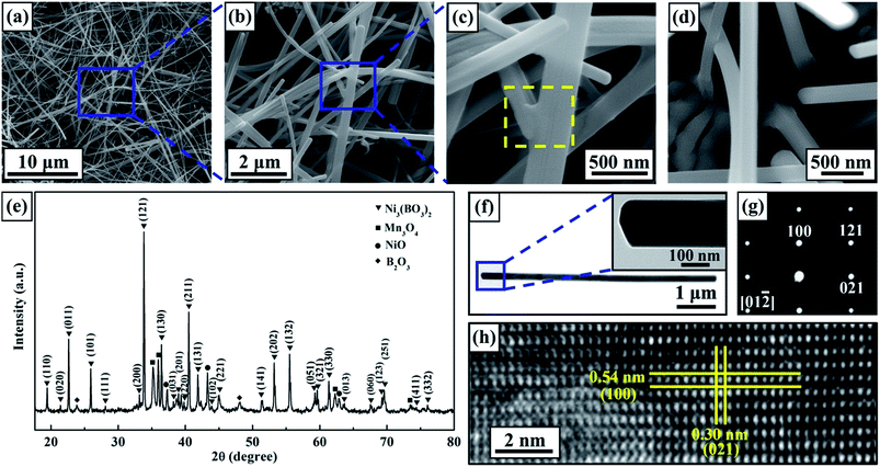
Based on our previous study,39 nanowhiskers were first synthesized at 950 °C for 4 h in air. Fig. 1(a) and (b) present SEM images of the surface morphologies of the products, which consisted of assembled nanowhiskers at multiple length scales. Most of the nanowhiskers had lengths in the range of 20–50 μm, forming an open porous network. The high-magnification image presented in Fig. 1(c) shows that the majority of the as-produced nanowhiskers had diameters ranging from 120 nm to 250 nm, whereas a small fraction of the nanowhiskers had thicker diameters of ∼500 nm, indicating that the nanowhiskers had an ultra-high aspect ratio of more than 100![[thin space (1/6-em)]](https://www.rsc.org/images/entities/char_2009.gif) :
:![[thin space (1/6-em)]](https://www.rsc.org/images/entities/char_2009.gif) 1. In addition, it is worth noting that bonding between nanowhiskers was observed, as shown in Fig. 1(c) (indicated by the yellow box). Such self-assembled bonding should enhance the stability of the three-dimensional porous network. Unlike the 1D nanostructures fabricated using the traditional solid-state reaction method or flux method,18,40,41 the nanowhiskers obtained in this study were not free-standing, being grown in situ on the substrate surface. Fig. 1(d) shows the roots of several nanowhiskers, implying good robustness between the as-grown nanowhiskers and the substrate. To identify the phase structure of the nanowhiskers, the XRD diffractograms (Fig. 1(e)) of the product were analyzed. It was observed that nearly all diffraction peaks could be indexed to the orthorhombic phase of Ni3(BO3)2 (JCPDS no. 22-0745) with lattice parameters of a = 0.54 nm, b = 0.83 nm, and c = 0.45 nm.
1. In addition, it is worth noting that bonding between nanowhiskers was observed, as shown in Fig. 1(c) (indicated by the yellow box). Such self-assembled bonding should enhance the stability of the three-dimensional porous network. Unlike the 1D nanostructures fabricated using the traditional solid-state reaction method or flux method,18,40,41 the nanowhiskers obtained in this study were not free-standing, being grown in situ on the substrate surface. Fig. 1(d) shows the roots of several nanowhiskers, implying good robustness between the as-grown nanowhiskers and the substrate. To identify the phase structure of the nanowhiskers, the XRD diffractograms (Fig. 1(e)) of the product were analyzed. It was observed that nearly all diffraction peaks could be indexed to the orthorhombic phase of Ni3(BO3)2 (JCPDS no. 22-0745) with lattice parameters of a = 0.54 nm, b = 0.83 nm, and c = 0.45 nm.
The detailed structure of the Ni3(BO3)2 nanowhiskers was further characterized through TEM examination (Fig. 1(f)–(h)). Fig. 1(f) presents a TEM image of an individual Ni3(BO3)2 nanowhisker with a uniform diameter of 170 nm. The high-magnification TEM image presented in the inset of Fig. 1(f) shows that the tip of the individual Ni3(BO3)2 nanowhisker presented a polyhedral morphology, which could also be observed in the SEM images (Fig. S1†). The selected-area electron diffraction (SAED) pattern acquired in the [01![[2 with combining macron]](https://www.rsc.org/images/entities/char_0032_0304.gif) ]-axis zone shown in Fig. 1(g) indicated that the nanowhisker was single-crystalline. The HRTEM image presented in Fig. 1(h) suggests that the [021] crystallographic direction is a possible growth direction of individual Ni3(BO3)2 nanowhiskers. No dislocations or stacking faults were observed in the examined area. In addition to products with uniform diameters, several Ni3(BO3)2 nanowhiskers were found that exhibited a diameter transition along the growth direction (Fig. S2†). The TEM results reveal that the lattice structures of the transition zone and the two adjacent regions were uniform. No stacking faults or lattice mismatches were observed in the transition zone, implying good crystallinity.
]-axis zone shown in Fig. 1(g) indicated that the nanowhisker was single-crystalline. The HRTEM image presented in Fig. 1(h) suggests that the [021] crystallographic direction is a possible growth direction of individual Ni3(BO3)2 nanowhiskers. No dislocations or stacking faults were observed in the examined area. In addition to products with uniform diameters, several Ni3(BO3)2 nanowhiskers were found that exhibited a diameter transition along the growth direction (Fig. S2†). The TEM results reveal that the lattice structures of the transition zone and the two adjacent regions were uniform. No stacking faults or lattice mismatches were observed in the transition zone, implying good crystallinity.
3.2. Effects of the growth temperature, holding time and amount of agent on the morphology of Ni3(BO3)2 nanowhiskers
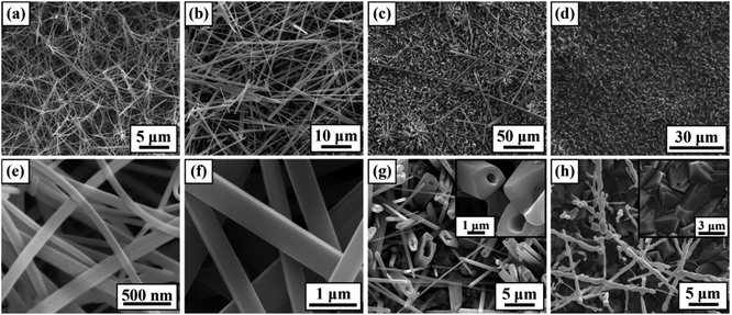
To obtain an in-depth understanding of the anisotropic growth of Ni3(BO3)2 nanowhiskers on an Ni substrate, a series of systematic experiments was conducted to investigate the effects of the growth temperature, holding time, and amount of added MnO2 on the nanowhisker formation. First, the effect of the growth temperature on the morphology of the final products was investigated. The holding time was fixed to 4 h for 900–1000 °C and to 2 h for 1050–1100 °C, and the amount of MnO2 agent was fixed to 3 wt%. Fig. 2 presents SEM images of the as-produced Ni3(BO3)2 nano-/microstructures fabricated at 900 °C to 1100 °C. The product synthesized at a relatively low growth temperature (900 °C) presented a three-dimensional porous network morphology, as shown in Fig. 2(a); this morphology was similar to that of the Ni3(BO3)2 nanowhiskers fabricated at 950 °C (Fig. 1(a)) but with a smaller interspacing. The high-magnification image (Fig. 2(e)) corresponding to Fig. 2(a) indicates that the nanowhiskers had diameters ranging from 75 nm to 130 nm. Because of the smallness of these diameters, the aspect ratio of the Ni3(BO3)2 nanowhiskers shown in Fig. 2(a) was as high as 200![[thin space (1/6-em)]](https://www.rsc.org/images/entities/char_2009.gif) :
:![[thin space (1/6-em)]](https://www.rsc.org/images/entities/char_2009.gif) 1. When the growth temperature was 1000 °C (Fig. 2(b) and (f)), abundant straight Ni3(BO3)2 nanowhiskers with diameters predominantly between 400 nm and 650 nm were obtained, although some whiskers had thicker diameters of up to 1 μm. Fig. 2(f) reveals that the nanowhiskers presented a quadrangular morphology with smooth planes. For a growth temperature of 1050 °C, the product consisted of abundant Ni3(BO3)2 microtubes with varisized hollow inner cavities and several hollow microwhiskers with lengths longer than 150 μm (Fig. 2(c) and (g)). The high-magnification image in Fig. 2(g) reveals that the microtubes grew in situ from the substrate surface, whereas the microwhiskers shown in Fig. 2(c) were free-standing. When the growth temperature was higher than 1100 °C, almost no nanowhiskers were observed on the substrate surface (Fig. 2(d)). Fig. 2(h) indicates that the few whiskers that grew during the heating process decomposed at this high temperature (1100 °C), and the substrate surface was covered by a large number of microscale hillocks with nanoscale holes at some of their tips. This morphological transformation may have been induced by the excess energy present at such a high growth temperature, which can induce molecular aggregation to decrease the surface energy.11,42 Based on the above observations, the growth temperature can significantly affect the morphologies of the products.
1. When the growth temperature was 1000 °C (Fig. 2(b) and (f)), abundant straight Ni3(BO3)2 nanowhiskers with diameters predominantly between 400 nm and 650 nm were obtained, although some whiskers had thicker diameters of up to 1 μm. Fig. 2(f) reveals that the nanowhiskers presented a quadrangular morphology with smooth planes. For a growth temperature of 1050 °C, the product consisted of abundant Ni3(BO3)2 microtubes with varisized hollow inner cavities and several hollow microwhiskers with lengths longer than 150 μm (Fig. 2(c) and (g)). The high-magnification image in Fig. 2(g) reveals that the microtubes grew in situ from the substrate surface, whereas the microwhiskers shown in Fig. 2(c) were free-standing. When the growth temperature was higher than 1100 °C, almost no nanowhiskers were observed on the substrate surface (Fig. 2(d)). Fig. 2(h) indicates that the few whiskers that grew during the heating process decomposed at this high temperature (1100 °C), and the substrate surface was covered by a large number of microscale hillocks with nanoscale holes at some of their tips. This morphological transformation may have been induced by the excess energy present at such a high growth temperature, which can induce molecular aggregation to decrease the surface energy.11,42 Based on the above observations, the growth temperature can significantly affect the morphologies of the products.
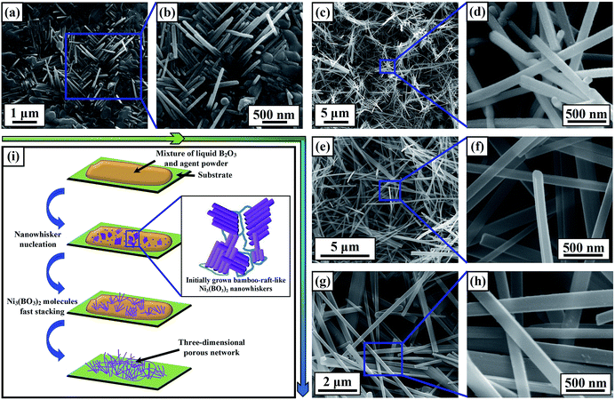
Fig. 3(a)–(h) present SEM images of the Ni3(BO3)2 nanowhiskers synthesized at 950 °C for various holding times with 3 wt% agent. When the source materials were merely heated to the growth temperature and then immediately allowed to cool, only a few Ni3(BO3)2 nanowhiskers with diameters ranging from 50 nm to 70 nm and lengths of ∼1 μm were observed on some portions of the substrate surface (Fig. 3(a) and (b)). From Fig. 3(b), it is clearly evident that the initially grown Ni3(BO3)2 nanowhiskers, which were essentially perpendicular to the corresponding fine substrate surface, presented a bamboo-raft-like morphology. The rough surfaces of the nanowhiskers imply that the Ni3(BO3)2 molecules were undergoing fast stacking. Fig. 3(c) and (d) presents images of the Ni3(BO3)2 nanowhiskers maintained at 950 °C for 30 min, which reveal that the substrate surface became covered by thicker (diameters of approximately 130 nm) and longer nanowhiskers than those observed in Fig. 3(b). With an increase in the holding time to over 1 h, a much more homogeneous three-dimensional porous network could be obtained (Fig. 3(e)–(h)). Fig. 3(i) schematically illustrates the growth process of the Ni3(BO3)2 nanowhiskers.
In addition, compared with our previous work, the yield of Ni3(BO3)2 nanowhiskers was significantly increased by the addition of the MnO2 agent. Therefore, we subsequently studied the effect of the amount of agent on the product morphology. When 10 wt% MnO2 was added to the source powder, abundant nanowhiskers were obtained, especially free-standing nanowhiskers, as well as residual manganese oxide bulk structures (Fig. S3†).
3.3. Possible growth mechanism of Ni3(BO3)2 nanowhiskers
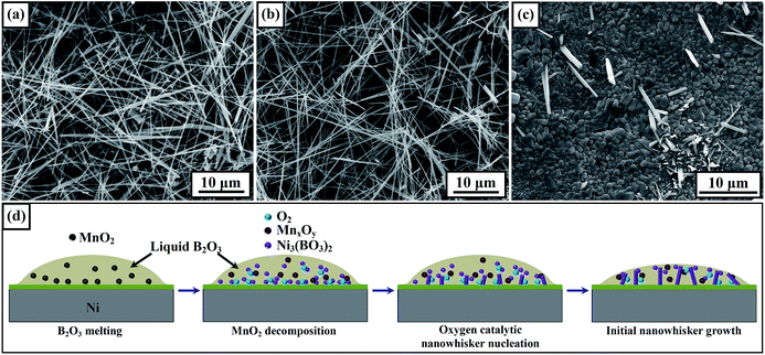
Similar to the growth process of Ni3(BO3)2 nanowhiskers fabricated via the direct heating of a mixture of Ni and boron powders in our previous study,39 the predominant reaction driving nanowhisker growth in this study was B2O3 (l) + NiO (s) → Ni3(BO3)2 (s). Because no impurities were observed at the ends of the Ni3(BO3)2 nanowhiskers in the SEM and TEM images, the Ni3(BO3)2 nanowhisker growth seems to have followed the self-catalytic mechanism,3,9,11 which is same as that for nanowhisker formation without the addition of the MnO2 agent. However, because the yield of Ni3(BO3)2 nanowhiskers significantly increased when MnO2 was added to the source powder, the detailed role of the MnO2 agent deserves further attention. Because of the decomposition of MnO2 into Mn2O3 at 535 °C and its further decomposition into Mn3O4 at 940 °C, leading to the release of oxygen, the powder mixtures of B2O3 + 3 wt% Mn2O3 and B2O3 + 3 wt% Mn3O4 were first milled. Fig. 4(a) and (b) present SEM images of the products fabricated with the addition of Mn2O3 and Mn3O4, respectively, as agents. Ni3(BO3)2 nanowhiskers were clearly observed in both cases, indicating that the manganese oxides played similar roles in the nanowhisker growth process. The relatively small diameters of the Ni3(BO3)2 nanowhiskers observed in Fig. 4(b) imply hysteresis in the nanowhisker growth, which may have been induced by a lack of oxygen during the initial growth stage. In addition, the same growth process as that for the product shown in Fig. 4(a) and (b) was performed in a vacuum furnace. The SEM image presented in Fig. 4(c) reveals the presence of only a few short whiskers, demonstrating the critical role of oxygen in the nanowhisker growth process. In addition to the critical role of the degree of supersaturation in processes of 1D-nanostructure formation,11,43,44 we propose an oxygen catalytic mechanism for the nucleation of Ni3(BO3)2 nanowhiskers and an atmosphere-solid composite catalytic mechanism for the nanowhisker growth process observed in this study. A schematic diagram of the proposed mechanism is presented in Fig. 4(d). The partial excess content of oxygen in liquid B2O3 facilitates nucleation at the solid–liquid interface. These active sites minimize the interfacial energy barrier for the subsequent growth of 1D nanostructures on the solid substrate.25 However, the addition of too much MnO2 may induce regnant nucleation in the bulk solution, leading to the formation of free-standing nanowhiskers. An increased fraction of free-standing nanowhiskers will degrade the persistence of the three-dimensional porous network on the Ni substrate.Additionally, some alternative agents, such as KClO3, KCl, K2SO4 and NaCl, were used to help synthesize Ni3(BO3)2 nanowhiskers. The corresponding SEM images of the products show that only a few short microrods were obtained (Fig. S4†). Further exploring experiments are under way to find an alternative agent that can help to synthesize nanowhiskers possessing narrower size distributions.
3.4. Hydrophilic properties of the Ni3(BO3)2-nanowhisker-coated surfaces
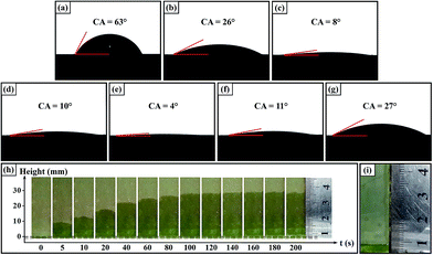
To examine the wettability of the surfaces on which the Ni3(BO3)2 nanowhiskers had grown, a series of wetting experiments was conducted. The final wetting time for a water droplet (∼10 μL) added to a surface was constrained to be no more than 10 s to minimize water evaporation from the rough surfaces. Fig. 5(a)–(g) present the wetting results for water droplets on Ni and NiO surfaces as well as surfaces coated with Ni3(BO3)2 nano-/microstructures. For the initial Ni and NiO surfaces, the intrinsic water contact angles (CA) were 63° (Fig. 5(a)) and 26° (Fig. 5(b)), respectively. As the Ni3(BO3)2 nanowhiskers were successfully grown in situ on the substrate surfaces, it was observed that the water contact angle of the nanowhisker-coated surfaces (Fig. 5(c) and (d)) decreased dramatically to less than 10°, indicating good hydrophilic wettability. Furthermore, a superhydrophilic surface was obtained when the nanowhisker growth temperature was 1000 °C, as was evident from its water contact angle of 4° (Fig. 5(e)). Because the wettability of a solid surface is governed by both its surface roughness and surface energy, it is obvious that the in situ-grown Ni3(BO3)2 nanowhiskers dramatically increased the surface roughness. In addition, the three-dimensional porous network of ultra-high-aspect-ratio nanowhiskers enhanced the capillarity of the surface, contributing to the formation of superhydrophilic surfaces. Importantly, such superhydrophilic surfaces do not require photogeneration and exhibit good thermal stability. When the products on the substrate surface were relatively short microtubes and long hollow microwhiskers (Fig. 2(c)), a surface with good hydrophilic property could also be obtained, as indicated by its water contact angle of 11° (Fig. 5(f)); this phenomenon may be attributable to the role played by the hollow inner cavities of the product structure in promoting water absorption. As the 1D nano-/microstructures decomposed at high growth temperatures, the good wettability of the surface was lost (Fig. 5(g)).The capillary action of water through the Ni3(BO3)2-nanowhisker-coated surface was also tested. This capillary rise investigation method, which has been suggested by Sekulic,45 is an effective approach to test the wettability of a rough surface. The wicking region is distinguished by a bright grayish-green domain in the images presented in Fig. 5(h). It can be observed that the front position, corresponding to the height to which the water was drawn through capillary action, reached 29 mm when the nanowhisker-coated plate was allowed to remain in the water container for 200 s. However, water could not be pulled up onto a plate that was lacking nanowhiskers (Fig. 5(i)).
3.5. Wetting dynamics of the Ni3(BO3)2-nanowhisker-coated surfaces
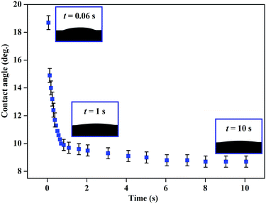
Since the surfaces with good hydrophilic wettability were obtained, it is significant to explore the wetting dynamics on Ni3(BO3)2 nanowhiskers coated surfaces. Fig. 6 shows the water contact angle values of the surface fabricated at 950 °C as a function of elapsed time. It can be clearly seen that the contact angle rapidly decreased to less than 10° within 1 s, implying the strong absorption of water into the porous network. The relationship between the contact angle and the rough surface can be described by Wenzel equation:46–49
cos![[thin space (1/6-em)]](https://www.rsc.org/images/entities/char_2009.gif) θw = r θw = r![[thin space (1/6-em)]](https://www.rsc.org/images/entities/char_2009.gif) cos cos![[thin space (1/6-em)]](https://www.rsc.org/images/entities/char_2009.gif) θ θ
| (1) |
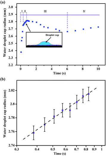
For a liquid penetrated rough surface, the “Cassie impregnating” state has been described by Niu,50 Zang51,52 and Bahners,53 etc. The explanation of the Cassie impregnating state is that the surface is partially wetted in front of the triple line and the rough surface can be considered as a composite surface with the liquid penetrating the texture. In addition, similar analysis on wetting dynamics was presented in Cazabat's research.54,55 In Cazabat's theory, a tiny film of liquid always precedes the droplet, and the spreading process can be divided into three stages. The initial stage is similar to the wetting process on smooth surfaces, which is lacking on very rough surfaces. Then, as the drop spreads, a regime consisting of a spherical cap and the precursor liquid film appears. Eventually, all liquid is consumed by the rough surface, resulting in the slowing down of the spreading rate. Actually, the wetting process of a water droplet on Ni3(BO3)2 nanowhiskers coated surfaces partially agrees with the Cazabat's theory. Fig. 7(a) shows the relationship between the radius of the droplet cap and the elapsed time. In contrast to Cazabat's research, the wetting process in Fig. 7(a) was divided into four stages. In the first stage, the droplet spread out rapidly on the nanowhiskers coated surface in the initial 0.3 s, corresponding to the rapid decrease of the contact angle (Fig. 6), which is different from the first stage described in Cazabat's theory. The reason for this difference is mainly because of the strong capillary force induced penetrating as mentioned above, and the radii variation seems to be linear (stage I in Fig. 7(a)). As the composite penetrating layer formed after the first spreading stage, the roughness in front of the triple line decreased, leading to the second wetting stage (the schematic was inserted in Fig. 7(a)). This stage is similar to that in Cazabat's theory. During stage II, the edge of the spreading rim can be described by the equation:54
| r(t) ∝ tn | (2) |
| rc(t) ∝ t1/18 | (3) |
Based on eqn (2) and (3), a conversion is obtained,
log![[thin space (1/6-em)]](https://www.rsc.org/images/entities/char_2009.gif) r(t) ∝ n r(t) ∝ n![[thin space (1/6-em)]](https://www.rsc.org/images/entities/char_2009.gif) log log![[thin space (1/6-em)]](https://www.rsc.org/images/entities/char_2009.gif) t t
| (4) |
Corresponding to eqn (4), the relationship between the logarithmic cap radius and the logarithmic time in wetting stage II is shown in Fig. 7(b). Then, the law of the spreading dynamics in stage II was found to be
| rc(t) ∝ t1/40 | (5) |
As the volume of the droplet cap decreased to a critical value, the liquid absorption capacity of the unwetted region was stronger than the liquid supply capacity of the central droplet, resulting in the decrease of the cap radius (stage III). After the porous network, within a relatively larger region in contrast to the cap, was filled with liquid, the radius of the residual droplet cap can reincrease in a small degree (stage IV).
As to the Ni3(BO3)2 nanowhiskers coated superhydrophilic surface (fabricated at 1000 °C, Fig. 2(b) and (f)), the outstanding wettability might be driven by the capillary force. Duprat et al.56 reported that the drop shapes highly depend on the ratio of the distance between the 1D nanostructures, 2d0 (measured from their outer surfaces), and their diameters, 2r. Duprat suggested that a drop forms for d0/r > √2, a column forms for d0/r < 0.57 and a barrel shape forms for 0.57 < d0/r < √2. Compared with the Ni3(BO3)2 nanowhiskers on the surfaces produced at 900 °C and 950 °C, the nanowhiskers fabricated at 1000 °C have larger diameters, which decreases the value of d0/r to some extent. Thus, it is beneficial to form a barrel or a column. Furthermore, the nanowhiskers with ultralong aspect ratio might be flexed by the capillary force, resulting in a complete wetting (Fig. S5†). Associated with the wetting process mentioned in Fig. 7, the in situ grown Ni3(BO3)2 nanowhiskers induced superhydrophilic phenomenon can be explained.
4. Conclusions
In summary, we successfully synthesized 1D Ni3(BO3)2 nanowhiskers in situ on Ni substrates via the facile molten-salt method using MnO2 as the agent. The Ni3(BO3)2 nanowhiskers fabricated at 950 °C had lengths ranging from 20 to 50 μm and diameters in the range of 120–250 nm. HRTEM images demonstrated that nanowhiskers with ultra-high aspect ratios of more than 100![[thin space (1/6-em)]](https://www.rsc.org/images/entities/char_2009.gif) :
:![[thin space (1/6-em)]](https://www.rsc.org/images/entities/char_2009.gif) 1 grew along the [021] crystallographic direction. The shapes and average sizes of the products were strongly dependent on the growth temperature and holding time. Additionally, we found that the oxygen content at the liquid–solid interface significantly affected the nucleation and thus the yield of the Ni3(BO3)2 nanowhiskers. Furthermore, the Ni3(BO3)2-nanowhisker-coated surfaces presented good superhydrophilic properties.
1 grew along the [021] crystallographic direction. The shapes and average sizes of the products were strongly dependent on the growth temperature and holding time. Additionally, we found that the oxygen content at the liquid–solid interface significantly affected the nucleation and thus the yield of the Ni3(BO3)2 nanowhiskers. Furthermore, the Ni3(BO3)2-nanowhisker-coated surfaces presented good superhydrophilic properties.
Acknowledgements
The authors gratefully acknowledge the financial support from the National Natural Science Foundation of China under grant no. 51275133. The authors would also like to acknowledge the National Natural Science Foundation of China under Grants no. 51321061 and no. 51405099.Notes and references
- A. Majchrowski, A. Wojciechowski, I. V. Kityk, M. Chrunik, L. R. Jaroszewicz and E. Michalski, J. Alloys Compd., 2014, 610, 82–85 CrossRef CAS PubMed.
- M. Bae, B. Kim, D. Ha, S. J. Lee, R. Sharma, K. J. Choi, J. Kim, W. J. Choi and J. C. Shin, Cryst. Growth Des., 2014, 14, 1510–1515 CAS.
- X. Tao, X. Wang and X. Li, Nano Lett., 2007, 7, 3172–3176 CrossRef CAS PubMed.
- R. Ma, Y. Bando and T. Sato, Appl. Phys. Lett., 2002, 81, 3467–3469 CrossRef CAS PubMed.
- D. K. Bediako, Y. Surendranath and D. G. Nocera, J. Am. Chem. Soc., 2013, 135, 3662–3674 CrossRef CAS PubMed.
- X. Fan, L. Zang, M. Zhang, H. Qiu, Z. Wang, J. Yin, H. Jia, S. Pan and C. Wang, Chem. Mater., 2014, 26, 3169–3174 CrossRef CAS.
- D. K. Bediako, B. Lassalle-Kaiser, Y. Surendranath, J. Yano, V. K. Yachandra and D. G. Nocera, J. Am. Chem. Soc., 2012, 134, 6801–6809 CrossRef CAS PubMed.
- H. Li, Z. Li, L. Qi and H. Oy, Scr. Mater., 2009, 61, 512–515 CrossRef CAS PubMed.
- X. Tao and X. Li, Nano Lett., 2008, 8, 505–510 CrossRef CAS PubMed.
- H. Y. Yue, J. Chang, X. Gao, S. L. Zhang, J. J. Zhang, H. Zhang, W. D. Fei, Z. M. Yu, E. J. Guo, F. W. Kang and L. P. Wang, Mater. Sci. Eng., A, 2014, 607, 89–94 CrossRef CAS PubMed.
- L. Bao, Z.-H. Xu, R. Li and X. Li, Nano Lett., 2010, 10, 255–262 CrossRef CAS PubMed.
- W. Zhu, X. Wang, X. Zhang, H. Zhang and Q. Zhang, Cryst. Growth Des., 2011, 11, 2935–2941 CAS.
- S. Liu, J. Liu, H. Du, F. Hou, S. Ren and H. Geng, RSC Adv., 2014, 4, 9451–9456 RSC.
- D. E. Terry and J. L. Jakobsen, US Pat., 2 784 232, 1957.
- Menaka, S. E. Lofland, K. V. Ramanujachary and A. K. Ganguli, J. Organomet. Chem., 2010, 695, 1002–1005 CrossRef CAS PubMed.
- Menaka, S. Sharma, K. V. Ramanujachary, S. E. Lofland and A. K. Ganguli, J. Colloid Interface Sci., 2011, 360, 393–397 CrossRef CAS PubMed.
- X. Liu, W. Zhu, X. Cui, T. Liu and Q. Zhang, Powder Technol., 2012, 222, 160–166 CrossRef CAS PubMed.
- H. Pang, Q. Lu, C. Chen, X. Liu and F. Gao, J. Mater. Chem., 2011, 21, 13889–13894 RSC.
- W. Götz, Naturwissenschaften, 1963, 50, 567 CrossRef.
- J. Pardo, M. Martinez-Ripoll and S. García-Blanco, Acta Crystallogr., Sect. B: Struct. Crystallogr. Cryst. Chem., 1974, 3, 37–40 CrossRef.
- A. Pakdel, C. Zhi, Y. Bando and D. Golberg, Mater. Today, 2012, 15, 256–265 CrossRef CAS.
- T. Guo, Y. Luo, Y. Zhang, Y. Lin and C. Nan, Cryst. Growth Des., 2014, 14, 2329–2334 CAS.
- S. H. Park, S. H. Kim, S. Y. Park and C. Lee, RSC Adv., 2014, 4, 63402–63407 RSC.
- R. Fu, S. Hu and X. Wu, Cryst. Growth Des., 2014, 14, 6197–6204 CAS.
- N.-R. Chiou, C. Lu, J. Guan, L. J. Lee and A. J. Epstein, Nat. Nanotechnol., 2007, 2, 354–357 CrossRef CAS PubMed.
- Q. Liu, A. A. Patel and L. Liu, ACS Appl. Mater. Interfaces, 2014, 6, 8996–9003 CAS.
- Y. Kim, S. Lee, H. Cho, B. Park, D. Kim and W. Hwang, ACS Appl. Mater. Interfaces, 2012, 4, 5074–5078 CAS.
- K. Tang, X. Wang, W. Yan, J. Yu and R. Xu, J. Membr. Sci., 2006, 286, 279–284 CrossRef CAS PubMed.
- A. Egatz-Gomez, R. Majithia, C. Levert and K. E. Meissner, RSC Adv., 2012, 2, 11472–11480 RSC.
- J. Zang, C. M. Li, S.-J. Bao, X. Cui, Q. Bao and C. Q. Sun, Macromolecules, 2008, 41, 7053–7057 CrossRef CAS.
- W. Zhong, S. Liu, X. Chen, Y. Wang and W. Yang, Macromolecules, 2006, 39, 3224–3230 CrossRef CAS.
- H. Liu, J. Zhai and L. Jiang, Soft Matter, 2006, 2, 811–821 RSC.
- S. Nishimoto, M. Becchaku, Y. Kameshima, Y. Shirosaki, S. Hayakawa, A. Osaka and M. Miyake, Thin Solid Films, 2014, 558, 221–226 CrossRef CAS PubMed.
- X. Zhang, Y. Guo, Y. Liu, X. Yang, J. Pan and P. Zhang, Appl. Surf. Sci., 2013, 287, 299–303 CrossRef CAS PubMed.
- J. Yuan, X. Liu, O. Akbulut, J. Hu, S. L. Suib, J. Kong and F. Stellacci, Nat. Nanotechnol., 2008, 3, 332–336 CrossRef CAS PubMed.
- F.-M. Chang, S.-L. Cheng, S.-J. Hong, Y.-J. Sheng and H.-K. Tsao, Appl. Phys. Lett., 2010, 96, 114101 CrossRef PubMed.
- H. Wang, Z. Yang, J. Yu, Y. Wu, W. Shao, T. Jiang and X. Xu, RSC Adv., 2014, 4, 33730–33738 RSC.
- F. Shi, X. Chen, L. Wang, J. Niu, J. Yu, Z. Wang and X. Zhang, Chem. Mater., 2005, 17, 6177–6180 CrossRef CAS.
- J. Cao, Y. Wang, X. Song and J. Feng, RSC Adv., 2014, 4, 19221–19225 RSC.
- Y. S. Hor, Z. L. Xiao, U. Welp, Y. Ito, J. F. Mitchell, R. E. Cook, W. K. Kwok and G. W. Crabtree, Nano Lett., 2005, 5, 397–401 CrossRef CAS PubMed.
- K. Teshima and H. Wagata, Cryst. Growth Des., 2012, 12, 4890–4896 CAS.
- Z. Wang and X. Feng, J. Phys. Chem. B, 2003, 107, 13563–13566 CrossRef CAS.
- Y. Zhang, N. Wang, S. Gao, R. He, S. Miao, J. Liu, J. Zhu and X. Zhang, Chem. Mater., 2002, 14, 3564–3568 CrossRef CAS.
- Y. Xia, P. Yang, Y. Sun and Y. Wu, Adv. Mater., 2003, 15, 353–389 CrossRef CAS.
- W. Liu, Y. Li, Y. Cai and D. P. Sekulic, Langmuir, 2011, 27, 14260–14266 CrossRef CAS PubMed.
- R. N. Wenzel, Ind. Eng. Chem., 1936, 28, 988–994 CrossRef CAS.
- J. Bico, U. Thiele and D. Quéré, Colloids Surf., A, 2002, 206, 41–46 CrossRef CAS.
- A. Pakdel, X. Wang, Y. Bando and D. Golberg, Acta Mater., 2013, 61, 1266–1273 CrossRef CAS PubMed.
- M. Nosonovsky and B. Bhushan, Scr. Mater., 2008, 59, 941–944 CrossRef CAS PubMed.
- J. J. Niu and J. N. Wang, Cryst. Growth Des., 2008, 8, 2793–2798 CAS.
- D. Zang, R. Zhu, C. Wu, X. Yu and Y. Zhang, Scr. Mater., 2013, 69, 614–617 CrossRef CAS PubMed.
- D. Zang, R. Zhu, W. Zhang, J. Wu, X. Yu and Y. Zhang, Corros. Sci., 2014, 83, 86–93 CrossRef CAS PubMed.
- T. Bahners, L. Prager and J. S. Gutmann, Langmuir, 2014, 30, 3127–3131 CrossRef CAS PubMed.
- A. M. Cazabat and M. A. Cohen Stuart, J. Phys. Chem., 1986, 90, 5845–5849 CrossRef CAS.
- A. M. Cazabat and M. A. Cohen Stuart, Prog. Colloid Polym. Sci., 1987, 74, 69–75 CrossRef.
- C. Duprat, S. Protière, A. Y. Beebe and H. A. Stone, Nature, 2012, 482, 510–513 CrossRef CAS PubMed.
Footnote |
| † Electronic supplementary information (ESI) available. See DOI: 10.1039/c5ra01783a |
| This journal is © The Royal Society of Chemistry 2015 |

